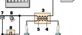
Voskhod 3M ignition circuit
Voskhod has installed an alternator on all of its models.
This separates all wiring into current sources and consumers, as well as auxiliary devices. The main advantage of such a system is that it works without a battery. The wiring diagram of the Voskhod 3M motorcycle is quite simple and identical to such Soviet mopeds as IZH Planet or Minsk. The system transmits current to the consumer through one wire carrying a positive charge. While the mass is the frame of the bike.
The electrical circuit of Voskhod 3M equipment consists of four independent circuits:
- ignition systems;
- headlights and sound signals;
- direction indicators;
- signal signs.
In addition, the ignition circuit of Voskhod 3M and subsequent models are provided with a non-contact ignition system and a 12V generator. To equalize the voltage, a stabilizer is combined with the switch. In such a system, the main cause of most malfunctions is a malfunction of the spark plugs or spark plug tip. Replacing them is quite simple and does not take much time.
However, with insufficient maintenance, interruptions in the operation of the motor occur. To avoid problems, it is necessary to clean the terminals on the contacts as often as possible and monitor the integrity of the wires. Otherwise, the system is very reliable and maintainable.
Source
Setting up BSZ Voskhod 3M
In 1983, the Kavrovsky plant launched the modernized Voskhod 3M motorcycle. The purpose of the modernization was to improve the operational and technical characteristics of the Voskhod motorcycle. The platform for creating the motorcycle was the Voskhod 2M model. Since the early 90s, serial production of the Voskhod 3M 01 modification began. But still, many owners of this device are not satisfied with the appearance. Therefore, in this article we will talk about tuning sunrise 3m.
Transmission
During transmission repairs, the following work may be required:
Most of them require high qualifications and are difficult to do at home. The exception is the repair and replacement of drive mechanisms. So, sometimes there is a need to restore the splines for the gearbox foot, replace the clutch cable or its jacket, or adjust the clutch. These works are carried out without disassembling the crankcase.
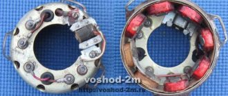
Generator Voskhod G-427
Generator G-427 alternating current with excitation from a permanent magnet with an inductive sensor of the electronic ignition system. In the grooves of the stator, made of stamped electrical steel plates, eight coils are placed, which form four independent circuits: - power supply to the ignition storage capacitor; — lighting and sound signal; — direction indicators; — braking signal.
Voltage regulation in the circuits of lighting loads is carried out according to the principle of parametric regulation, i.e. The winding data of the generator are selected in such a way that as the rotor speed increases, the voltage at the generator terminals changes within certain limits for a certain load. Attaching the generator stator to the engine crankcase provides adjustment of the ignition timing.
On the generator stator cover there are terminals: - charging coils of the power supply circuit of the Voskhod ignition storage capacitor; — direction indicators; — brake signal; — lighting; — sensor.
Which are marked accordingly: >, >, >, > and >.
The sensor is mounted on the generator stator cover using screws.
Generator rotor
The generator rotor with the sensor rotor located on it is mounted on the right axle axis of the engine crankshaft with a bolt and is secured against rotation by a key.
Motorcycle ignition installation sunrise
The electrical equipment of the Voskhod 2m motorcycle includes a G-427 generator, a KET-1 switch, a high-voltage transformer, a headlight, central and other switches.
Generator Voskhod G-427
Generator G-427 alternating current with excitation from a permanent magnet with an inductive sensor of the electronic ignition system. In the grooves of the stator, made of stamped electrical steel plates, eight coils are placed, which form four independent circuits: - power supply to the ignition storage capacitor; — lighting and sound signal; — direction indicators;
Voltage regulation in the circuits of lighting loads is carried out according to the principle of parametric regulation, i.e. The winding data of the generator are selected in such a way that as the rotor speed increases, the voltage at the generator terminals changes within certain limits for a certain load. Attaching the generator stator to the engine crankcase provides adjustment of the ignition timing.
On the generator stator cover there are terminals: - charging coils of the power supply circuit of the Voskhod ignition storage capacitor; — direction indicators; — brake signal; — lighting;
Which are marked accordingly: >, >, >, > and >.
The sensor is mounted on the generator stator cover using screws.
Generator rotor
The generator rotor with the sensor rotor located on it is mounted on the right axle axis of the engine crankshaft with a bolt and is secured against rotation by a key.
Caring for a sunrise motorcycle generator - how to remove, what to check and install correctly
Generator maintenance mainly comes down to tightening the threaded fasteners of the generator stator and rotor, as well as the wire terminals.
In order to remove the generator, you must:
Checking the removed parts
After removing the generator stator and rotor, wash the parts with clean gasoline and carefully inspect them. Disassemble the wire fastening terminals on the stator. Wipe dry all insulating parts of the terminals.
Generator installation
Installation is carried out in the reverse order, in this case it is necessary:
Ignition adjustment Voskhod
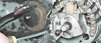
The ignition timing is set by turning the generator stator after first loosening the three screws securing the stator to the crankcase. For normal engine operation, it is necessary that the moment of spark formation (on the generator, this moment is determined by the coincidence of the sensor rotor groove with the protrusion on the sensor coil frame. Fig.) coincides with the moment when the piston does not reach the top dead center of 2.5-3.0 mm (at running the engine on gasoline with an octane rating of 92).
The gap between the rotor and the core of the sensor coil should be within 0.3±0.05mm.
The gap should be set as follows:
For more accurate ignition installation, it is recommended to determine the piston position with the cylinder head removed.
Coil Voskhod - high-voltage transformer B-300B
Switch Voskhod - electronic KET-1
The electronic switch KET-1 is designed to work in the ignition system complete with the G-427 generator and the B-300B high-voltage transformer. Allows you to obtain a secondary voltage of up to 18 kV, at a generator rotor speed of 250 to 7500 rpm. The switch is installed in the right toolbox. The base of the commutator is connected to the ground of the motorcycle. If the switch fails, it can be disassembled and repaired
The electronic switch has three output terminals with letter markings on the body >, > and >. The ground terminal is the base of the switch.
Maintaining the switch during operation comes down mainly to tightening the threaded connections, while avoiding stripping the threads. It is necessary to protect the switch from moisture getting inside it and onto the terminals from sudden shocks and exposure to high temperatures. You should also systematically check the reliability of the electrical connection of the switch base with >, because If this condition is violated, sparking on the spark plug stops.
Schematic diagram of an electronic switch
D1-D226B, D2-D226B, D3-D226B, D4-D817V, D5-D817B, D6-KU201L. C1 - 1 µF 250 V, C2 - 1 µF 160 V, C3 - 1 µF 160 V. R1 - 100 ohm, R2 - 1 com.
Point G - 45 volts, Point K - 150 volts, Point D - 0.65 volts.
Throttle type DR-100
Installed in the right tool box. From the generator braking signal circuit, through the throttle, which is a device that complements the parametric control of the generator, the circuit of the speedometer, city driving and license plate lighting lamps is powered.
Spark plug Voskhod - spark ignition type A-23
During operation, the spark plug must be periodically cleaned of carbon deposits and the gap between the electrodes must be adjusted, which should be within 0.6-0.7 mm, which is ensured by bending the outer electrode. To seal, a copper-asbestos gasket is placed between the spark plug and the cylinder head. To eliminate radio interference created by the ignition system, a shielded tip of type A-4 is placed on the spark plug.
Headlight Voskhod FG - 133
During operation it does not require special care. Basically, caring for the headlight comes down to removing dust from the internal cavity of the optical element by blowing air.
Caring for a sunrise motorcycle generator - how to remove, what to check and install correctly
Generator maintenance mainly comes down to tightening the threaded fasteners of the generator stator and rotor, as well as the wire terminals.
In order to remove the generator, you must:
- disconnect the wires of the ignition circuit, sensor, brake light and direction indicators from the generator terminals;
- unscrew the three screws securing the stator to the crankcase and remove the stator;
- Unscrew the bolt securing the generator rotor and, with light, careful blows of a wooden hammer on opposite sides of the rotor, remove it from the trunnion and remove the key.
Checking the removed parts
After removing the generator stator and rotor, wash the parts with clean gasoline and carefully inspect them. Disassemble the wire fastening terminals on the stator. Wipe dry all insulating parts of the terminals.
Generator installation
Installation is carried out in the reverse order, in this case it is necessary:
- check the runout of the generator rotor, which should be no more than 0.1 mm with the bolt secured;
- tighten the generator stator without distortions, ensuring a tight fit to all three supports;
- install the ignition correctly;
- The generator wires must be securely fastened and well insulated from each other.
Ignition adjustment Voskhod
The ignition timing is set by turning the generator stator after first loosening the three screws securing the stator to the crankcase. For normal engine operation, it is necessary that the moment of spark formation (on the generator, this moment is determined by the coincidence of the sensor rotor groove with the protrusion on the sensor coil frame. Fig.) coincides with the moment when the piston does not reach the top dead center of 2.5-3.0 mm (at running the engine on gasoline with an octane rating of 92).
The gap between the rotor and the core of the sensor coil should be within 0.3±0.05mm.
The gap should be set as follows:
- loosen the screws securing the sensor stator to the generator stator cover;
- By moving the sensor stator in the grooves of the generator stator cover, set the required gap, and then tighten the fastening screws.
For more accurate ignition installation, it is recommended to determine the piston position with the cylinder head removed.
Incendiary physics - advance, distributor and UOZ
How to set the ignition? What is UOZ? Where did the runners rotate in domestic cars? What does the expression “set by spark” mean? - there are many interesting questions to which owners of modern cars may not give the correct answers.
What is ignition timing - also known as ignition timing? Is this some kind of attribute of ancient cars or something unshakable, akin to universal gravity? Most modern car owners are unaware of this. All car systems are controlled by numerous controllers, and therefore timely sparking in the engine cylinders is entirely their responsibility. Meanwhile, a huge number of ancient machines are running around the country, unfamiliar with processors and other chips. Therefore, questions like “How to regulate the SOP?” still sound today.
It's always a pleasure to answer technical questions. But first you have to remember some “incendiary” terms.
Terminology
Ignition distributor
- an electromechanical device that ensures timely supply of high voltage pulses to the spark plugs.
It is often called a distributor
.
Contact and non-contact distributors for rear- and all-wheel drive carburetor VAZ cars
Contact and non-contact distributors for rear- and all-wheel drive carburetor VAZ cars
Ignition advance
- ignition of the working mixture in the cylinder before the compression stroke ends.
Ignition timing (IDA)
— the angle of rotation of the engine crankshaft from the position corresponding to the appearance of a spark on the spark plug until the piston reaches top dead center.
Contact ignition system
- a system in which switching of the ignition coil is provided by a mechanical interrupter.
Contactless ignition system
- a system in which switching of the ignition coil is provided by an electronic module controlled by an electronic crankshaft position sensor - for example, a Hall sensor (VAZ-2108) or magnetoelectric (GAZ-2410).
Breaker
ignition system - a mechanical switch in the distributor, directly connected to the primary circuit of the ignition coil.
Runner
- a distributor element that alternately transmits high voltage from the ignition coil to high-voltage wires connected to the engine spark plugs.
Angle of closed state of contacts (UZSK)
- a value indicating how long the contacts of a mechanical breaker should remain closed. For classic Zhiguli cars, the UZSK is approximately 55 degrees. A correctly selected UZSK gives the ignition coil the opportunity to gain the necessary energy and completely transfer it to the spark plugs.
When and why do you need to adjust the ignition?
First, a little theory. If the working mixture in the cylinders burned instantly, then there would be no problems with advance in principle. Set it on fire at top dead center and everything is fine. But the mixture does not burn instantly: it takes milliseconds. In this case, the actual rotation speed of the crankshaft is, of course, not constant. Therefore, you cannot stupidly ignite the mixture at the same time under different engine operating modes: it will burn either too early or too late. The result will always be disappointing - the engine pulls poorly, overheats, runs unstably, detonates, etc.
In particular, if you start “sparking” too early ( large
), then the gas pressure will increase sharply until the piston reaches top dead center, preventing its movement.
Because of this, the power will decrease and the efficiency of the engine will deteriorate, it will lose throttle response and will jerk at low speeds. With late sparking ( low CV
), the mixture will burn for a long time with an expanding volume, and therefore the gas pressure will be significantly lower than the calculated one. Power and efficiency will decrease, and the engine will overheat greatly, since the mixture will burn out throughout the entire expansion stroke.
There is only one treatment method - ignite the working mixture according to the speed and load on the engine. In addition, adjustment of the OZ may be required when switching to gasoline with a different octane number. By the way, on very ancient cars (at the beginning of the last century), the ignition timing was regulated by the driver: a special handle was provided. But it soon disappeared, because the engine acquired a distributor with a centrifugal mechanism inside.
Centrifugal and vacuum ignition timing mechanisms in a contact distributor
Centrifugal and vacuum ignition timing mechanisms in a contact distributor
The centrifugal regulator usually contained a pair of weights balanced by springs. As the rotation speed increased, the weights diverged to the sides and rotated the support plate on which the breaker was located. The higher the rotation speed, the more the weights diverge and the higher the SOP becomes.
The further pursuit of efficiency added a vacuum colleague to the centrifugal regulator as assistants. The fact is that as the load increases, the filling of the cylinders with the combustible mixture also increases, since the driver puts more pressure on the accelerator. At the same time, the percentage of residual gases in the working mixture decreases, which helps to increase the combustion rate. Therefore, the SOP must be reduced.
On the contrary, when the load on the engine decreases, the filling of the cylinders decreases, the content of residual gases increases, and therefore the working mixture will burn more slowly. In this case, the OZ needs to be increased. This problem is solved by a vacuum regulator that monitors the vacuum in the engine intake pipe. The higher the load, the lower the vacuum, and vice versa. In most classic engines, centrifugal and vacuum regulators work together.
If the octane number of the fuel does not correspond to the one that guided the designer when designing the engine, then even with optimal operation of the mentioned regulators, you should not expect normal operation of the engine. The most unpleasant phenomenon that can occur is detonation. Roughly speaking, this is an explosive combustion of the mixture, fraught with major repairs. To prevent detonation in classic engines of a bygone era, it was necessary to open the hood and manually turn the distributor housing in the desired direction. Filled with low-octane gasoline - if you please, delay the ignition...
It goes without saying that in modern engines the optimal SOP is set by the control controller. It monitors speed, load, octane number, temperature, etc.
Switch Voskhod - electronic KET-1
The electronic switch KET-1 is designed to work in the ignition system complete with the G-427 generator and the B-300B high-voltage transformer. Allows you to obtain a secondary voltage of up to 18 kV, at a generator rotor speed of 250 to 7500 rpm. The switch is installed in the right toolbox. The base of the commutator is connected to the ground of the motorcycle. If the switch fails, it can be disassembled and repaired
The electronic switch has three output terminals with letter markings on the body >, > and >. The ground terminal is the base of the switch.
Maintaining the switch during operation comes down mainly to tightening the threaded connections, while avoiding stripping the threads. It is necessary to protect the switch from moisture getting inside it and onto the terminals from sudden shocks and exposure to high temperatures. You should also systematically check the reliability of the electrical connection of the switch base with >, because If this condition is violated, sparking on the spark plug stops.
Voskhod motorcycle ignition and electrical equipment
The electrical equipment of the Voskhod 2m motorcycle includes a G-427 generator, a KET-1 switch, a high-voltage transformer, a headlight, central and other switches.
Caring for a sunrise motorcycle generator - how to remove, what to check and install correctly
Generator maintenance mainly comes down to tightening the threaded fasteners of the generator stator and rotor, as well as the wire terminals.
Coil Voskhod - high-voltage transformer B-300B
Switch Voskhod - electronic KET-1
The electronic switch KET-1 is designed to work in the ignition system complete with the G-427 generator and the B-300B high-voltage transformer. Allows you to obtain a secondary voltage of up to 18 kV, at a generator rotor speed of 250 to 7500 rpm. The switch is installed in the right toolbox. The base of the commutator is connected to the ground of the motorcycle. If the switch fails, it can be disassembled and repaired
Maintaining the switch during operation comes down mainly to tightening the threaded connections, while avoiding stripping the threads. It is necessary to protect the switch from moisture getting inside it and onto the terminals from sudden shocks and exposure to high temperatures. You should also systematically check the reliability of the electrical connection of the switch base with >, because If this condition is violated, sparking on the spark plug stops.
Spark plug Voskhod - spark ignition type A-23
During operation, the spark plug must be periodically cleaned of carbon deposits and the gap between the electrodes must be adjusted, which should be within 0.6-0.7 mm, which is ensured by bending the outer electrode. To seal, a copper-asbestos gasket is placed between the spark plug and the cylinder head. To eliminate radio interference created by the ignition system, a shielded tip of type A-4 is placed on the spark plug.
Headlight Voskhod FG - 133
During operation it does not require special care. Basically, caring for the headlight comes down to removing dust from the internal cavity of the optical element by blowing air.
Ignition switch Voskhod - central switch
Caring for the central switch comes down to periodically checking the reliability of the switch in the headlight and cleaning the moving and fixed contacts from dust and dirt by washing them in gasoline.
Switch P-200
Light switch with horn button (located on the left side of the steering wheel). To switch the low and high beam circuit, a P-200 type switch is used with a built-in push-button horn switch for three operating positions: neutral - the headlight lamp is off; far right - low beam is on; far left - high beam is on.
The horn button has a movable contact connected to ground and a fixed contact connected to one of the wires coming from the horn terminal. When you press the button, the contacts close and the signal circuit is completed.
Spark plug Voskhod - spark ignition type A-23
During operation, the spark plug must be periodically cleaned of carbon deposits and the gap between the electrodes must be adjusted, which should be within 0.6-0.7 mm, which is ensured by bending the outer electrode. To seal, a copper-asbestos gasket is placed between the spark plug and the cylinder head. To eliminate radio interference created by the ignition system, a shielded tip of type A-4 is placed on the spark plug.
How to set the ignition at sunrise 3m
The electrical equipment of the Voskhod 2m motorcycle includes a G-427 generator, a KET-1 switch, a high-voltage transformer, a headlight, central and other switches.
Caring for a sunrise motorcycle generator - how to remove, what to check and install correctly
Generator maintenance mainly comes down to tightening the threaded fasteners of the generator stator and rotor, as well as the wire terminals.
Coil Voskhod – high-voltage transformer B-300B
The high voltage transformer is located under the fuel tank and is used to convert low voltage current into high voltage current. The transformer consists of a core, primary and secondary windings, a housing and a cover with terminals. During operation it does not require maintenance and cannot be repaired.
Switch Voskhod – electronic KET-1
The electronic switch KET-1 is designed to work in the ignition system complete with the G-427 generator and the B-300B high-voltage transformer. Allows you to obtain a secondary voltage of up to 18 kV, at a generator rotor speed of 250 to 7500 rpm. The switch is installed in the right toolbox. The base of the commutator is connected to the ground of the motorcycle. If the switch fails, it can be disassembled and repaired
The electronic switch has three output terminals with letter markings on the body >, > and >. The ground terminal is the base of the switch.
Maintaining the switch during operation comes down mainly to tightening the threaded connections, while avoiding stripping the threads. It is necessary to protect the switch from moisture getting inside it and onto the terminals from sudden shocks and exposure to high temperatures. You should also systematically check the reliability of the electrical connection of the switch base with >, because If this condition is violated, sparking on the spark plug stops.
Spark plug Voskhod - spark ignition type A-23
During operation, the spark plug must be periodically cleaned of carbon deposits and the gap between the electrodes must be adjusted, which should be within 0.6-0.7 mm, which is ensured by bending the outer electrode. To seal, a copper-asbestos gasket is placed between the spark plug and the cylinder head. To eliminate radio interference created by the ignition system, a shielded tip of type A-4 is placed on the spark plug.
Headlight Voskhod FG – 133
During operation it does not require special care. Basically, caring for the headlight comes down to removing dust from the internal cavity of the optical element by blowing air.
Source: https://o-ladagranta.ru/kak-nastroit-zazhiganie-na-voshode-3m/
Ignition switch Voskhod - central switch
Switch 124005490201 is used as a central software switch that provides the necessary switching of lighting equipment on a motorcycle. The switch has three operating positions >, >, > in accordance with the following operating modes:
- in position > - the generator sensor circuit is shorted to ground, which ensures the engine stops.
- in the > position (driving during the day) - the ignition circuit is turned on, the direction indicator circuit operates (when the direction indicator switch is on) and the brake signal circuit (when the brake pedal is pressed);
- in position > (driving at night), two circuits are switched on:
- a) a circuit of speedometer backlight lamps, license plate lighting and city driving (through a throttle, which serves as a device that complements the parametric control of the generator);
- b) headlight lamp circuit A6-32+32 (via the light switch on the steering wheel).
Caring for the central switch comes down to periodically checking the reliability of the switch in the headlight and cleaning the moving and fixed contacts from dust and dirt by washing them in gasoline.
Switch P-200
Light switch with horn button (located on the left side of the steering wheel). To switch the low and high beam circuit, a P-200 type switch is used with a built-in push-button horn switch for three operating positions: neutral - the headlight lamp is off; far right - low beam is on; far left - high beam is on.
The horn button has a movable contact connected to ground and a fixed contact connected to one of the wires coming from the horn terminal. When you press the button, the contacts close and the signal circuit is completed.
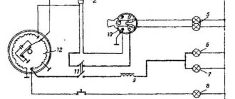
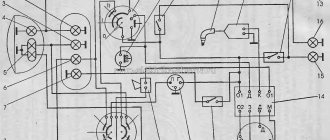
Electrical circuit of the Voskhod motorcycle
Central switch. 2. speedometer. 3. Speedometer light. 4. Headlight. 5. Headlight lamp. 6. City driving lamp. 7. Sound signal. 8. Direction indicator lamp. 9. Direction indicators. 10. Direction indicator switch. 11. Electronic switch. (D - sensor terminal, K - ignition coil terminal, G - generator terminal.) 12. Throttle. 13. Relay breaker. 14. Generator. 15. License plate lamp. 16. Brake signal lamp. 17. Rear light. 18. Wire connection block. 19. Brake light switch. 20. Shielded spark plug cap. 21. Spark plug. 22. High voltage wire. 23. Ignition coil. 24. Light switch.
Wire colors: sn. - blue, cf. - gray, g. - blue, g. - yellow, h. - green, k. - red, kor. - brown, op. - orange, f. - violet, h. - black.
Source
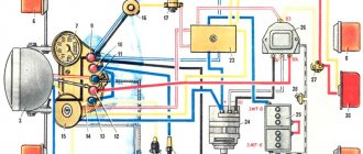
Ignition sunrise 3m generator connection diagram
Electrical circuit diagram of motorcycles Voskhod 3M-01, Sova 175, Sova 200, ZiD 200 Courier and all-terrain vehicle Farmer. This scheme can be applied to the ZiD 200 Tarpan all-terrain vehicle. The difference is insignificant (the Tarpan all-terrain vehicle has two headlights, versus the one shown in the diagram below).
The electrical circuit diagram can be downloaded with a high resolution of 7740x5400.
Markings and characteristics of lamps:
Lamp A12-1.2: voltage - 12 V, power - 1.2 W. Used in light filters for direction indicators and high beams.
Lamp AMN-12-3-1: voltage - 12 V, power - 3 W. Used for speedometer illumination.
Lamp A12-4: voltage - 12 V, power - 4 W. Used in headlight, side light.
Lamp A12-45+40: voltage - 12 V, power - 45 + 40 W, base type - P45t, lamp marking - R2. Used in headlight, high and low beam. It is allowed to use the AKG12-60+55 lamp: voltage - 12 V, power - 60 + 55 W.
Lamp A12-10: voltage - 12 V, power - 10 W. Used in direction indicators.
Lamp A12-21-3: voltage - 12 V, power - 21 W. Used in tail light, brake light.
Lamp A12-5: voltage - 12 V, power - 5 W. Used in rear light, parking light and license plate light.
Alternating current generator 80.3701 with excitation from permanent magnets, installed on motorcycles since 1992, voltage - 14 V, power - 90 W.
The BKS-1MK211 switch is designed to work with generators 26.3701 (6V 45W), G-427 (6V 65W), 43.3701 (12V 65W), 80.3701 (12V 90W), GM-02.02, GM-03.02, R71, 92.3702M-02.02, GM-03.02, R71, 92.3702.
Ignition coil (bobbin), also known as a high-voltage transformer, operating voltage 12 V, marking 2102.3705 TU 37.003.8UO-78
Spark plug A23-1, spark plugs from BOSCH W6BC or W7AC, or N14YC from BRISK can also be used.
Sound signal: voltage - 12 V, marking 12.3721-10. current consumption: 4.0 A; sound pressure level at a distance of 2 m no more than 90. 118; main sound frequency: 350. 450Hz
Source