Domestic Ural motorcycles are considered very reliable and durable equipment, capable of operating even in the most severe conditions. Such a vehicle is distinguished by a fairly simple design, maintainability, low sensitivity to fuel quality, as well as wide tuning capabilities. However, they also have a weak point, represented by the ignition system - the features of its design force motorcycle owners to interfere with the operation of the electrical system quite often. Every owner of domestic heavy equipment should know how to check the ignition coil on a Ural motorcycle. This information will be especially useful for owners of older motorcycles with a 6-volt ignition system, since their coil is subject to double the stress.
First signs of trouble
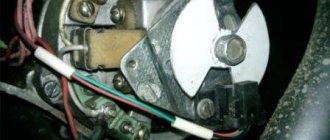
Before checking, the coil must be removed from the motorcycle using the available tools. Before removal, the part must be carefully disconnected from the connectors, and when removing it, you should be careful not to break its fragile fastening. Having taken out the coil, look carefully at its surface.
The main sign of a coil malfunction will be dark spots on the surface of the winding, as well as traces of melting, which indicate that excessive voltage is applied to the part. In addition, spots of oil or other foreign substances, which theoretically should not be in the ignition system, will be a reason to be wary. When the ignition operates without the motor running, clearly noticeable damage may appear on the surface of the winding, including breaks visible to the naked eye. However, you should not rely only on visual inspection - after inspection, the part is subjected to a thorough examination.
Electrical check
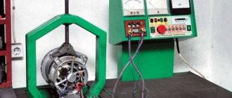
The ignition coil of the Ural motorcycle has a device quite familiar to such parts - a core made of electrical steel, as well as primary and secondary windings covered with insulation made of varnish and special tape. The functionality of this part is checked using an ohmmeter or multimeter with the appropriate function. Place the coil on the table in a position convenient for you, or place it on a thick layer of soft material that does not allow electricity to pass through (for example, foam rubber).
First, we measure the resistance level on the primary winding, which differs by winding a thicker wire. Normally, the indicator will be 6 ohms, and there should be no direct contact between the primary winding of the coil and the ground. However, it is not always possible to perform such a check - if the engine, although poorly, was working, the likelihood of finding a problem in the primary winding will be very small.
Therefore, having completed this procedure for order, proceed to measuring the resistance on the secondary winding. Checking the indicator at the high voltage terminals should show a result of 10 kOhm. In addition, you need to set one contact to ground, and alternately move the second between the two terminals - the result should be an infinity symbol on the multimeter screen or the ohmmeter needle moving to the right. Finally, take a ruler or caliper and measure the distance between the terminals and arresters - normally it should be 9 mm.
Leave it to mechanics or install electronics
Perhaps not all older motorcycle models are running. The Ural motorcycle sits and rusts in my grandfather’s barn because it won’t start.
The wheels are spinning, the engine is not jammed. Maybe the spark goes into the ground, as they say. In short, you need to look at the spark generation system. But even a working motorcycle, with a contact ignition system, causes unexpected and unpleasant problems for its owner:
- won't start when you really need it;
- with new oil rings in the engine, the spark plugs become covered with soot;
- there is no required engine power when driving with maximum load;
- the maximum speed is not reached;
- The battery is slightly discharged and the engine does not start.
Tuning a Ural motorcycle with your own hands - this article will help you decide in which direction to modernize your Ural.
The contact ignition system creates a lot of problems, especially when the moving parts in it have already worn out, backlash has appeared, and the geometry of the elements has changed.
The solution is simple - all cam ignition is thrown out, a modern electronic non-contact type spark generation system is installed. You will no longer have to deal with the thankless task of cleaning contacts and endlessly adjusting the gaps in the breaker. All this is possible thanks to the simple, but quite reliable design of the motorcycle. For example, it is quite easy to set the thermal gap and adjust the valves in the Urals with your own hands, using only your own tools from the garage. This way you will gain valuable experience and save money on visiting the workshop.
Express diagnostics
If the motorcycle begins to act up “in the field,” then removing and installing the ignition coil will become an almost impossible task. And even if you have a multimeter at hand, it will be incredibly difficult to perform the test. Therefore, it is worth using an alternative method for diagnosing the ignition system, which is often used in practice by experienced motorcyclists.
If the battery is more than half charged, you will be able to check the functionality of the ignition coil in a couple of minutes. To do this, you need to remove the contact cap of the spark plug and turn on the ignition, holding it by the insulated part. The distance between the cap and the candle should be 5–7 millimeters.
Hit the kickstarter hard and pay attention to the spark plug. If a spark forms between it and the cap, the ignition coil is in working order, and you should look for the cause of the failure in other parts of the motorcycle. In some cases, a spark is formed, but it appears rather weak and dull. This is usually due to the battery being low. However, if you are sure that the battery is charged, then most likely the problem is a breakdown of the ignition coil windings.
Contactless ignition system for motorcycle Ural, Dnepr
Solving the problem of the reliability of the ignition system on my Ural motorcycle, I came to the conclusion that it was necessary to install a BSZ...
Having considered the huge abundance of options for contactless ignition systems, both on the market and on the Internet, I decided to make for myself the simplest option for the electronic part. Namely, use a Zhiguli Hall sensor and switch. The reason for choosing this particular combination was that I like to travel far and for a long time, and you must admit that if a specific unit specifically for a motorcycle fails along the way, it is not always possible to find a replacement for Saurman or an opto sensor somewhere in the outback, just as it is not always possible to carry it with you contact ignition kit in reserve. And spare parts for Zhiguli can be found in any village.
Search for BSZ kit
So, the choice has been made, all that remains is to implement it. I went to the market. I bought a switch for a VAZ 2108, a Hall sensor and a piece of wiring from a VAZ 2107 distributor. I bought a two-terminal coil from Oka. I also needed an old breaker housing to make a mounting panel for the Hall sensor that I had.
How to make a butterfly for BSZ
The simplest, but not the most correct option was to make a modulator butterfly, ordering it from a turner, which could be rigidly fixed to the shaft. In this case, the ignition timing would remain constant all the time. Of course, it would be possible to add an additional FUOZ unit (ignition timing generator) to this option, but, based on my concept of “reliability in simplicity,” this option also did not suit me. I wanted the engine to work as it should, without complicating the electronic part, so I went to the market again and bought a new Ural cam with a centrifugal regulator. I approached the selection of the cam responsibly and bought the most reliable one, not a Chinese one.
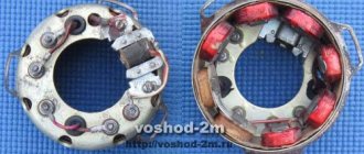
We make a plate for the hall sensor
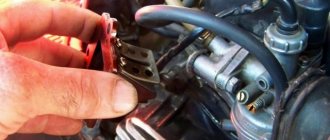
I took the old body from the breaker, removed all the insides from it, and sawed off the vertical walls to a horizontal plane. The result is a plate like this.
Next, having thought about how to secure the Hall sensor, I decided to “sink” it and secure it at the bottom of the plate, fortunately there was 3 mm of free space under the plate, just right for attaching the sensor. This mounting option seemed to me the most rigid, plus the sensor mounting screws will not be unscrewed due to engine vibrations, since they will rest against the housing. I made the necessary cut in the plate along the width of the sensor, drilled two holes and cut an M3 thread. I installed the Hall sensor on the plate and secured it with M3 screws with countersunk heads.
We manufacture a modulator for BSZ
I measured the vertical distance from the slot in the sensor to the edge of the plate. I got distances from the bottom edge of the sensor slot of 6 mm from the top of 10 mm. I installed the plate on the motorcycle, installed the cam with the centrifugal regulator in place, looked at how the lower edge of the cam sits in relation to the plate, it should be approximately at the same level. I transferred the distance from the plate to the center of the slot in the sensor to the cam body. In my case it turned out to be 8 mm. Marked a horizontal line. The curtains will be welded at this level. I left the marking line for release.
I measured the distance from the center of the shaft on which the cam sits to the Hall sensor housing through the slot - 28-29mm. I decided that the diameter of the butterfly should be 54 mm, so that there would be a gap of 2 mm between the edge of the curtain and the sensor body. Somewhere on the BSZ discussion forums I read that for the switch to work properly, a 2/1 cycle is required. That is, two parts of the sector are closed, one part is open. It turns out 120 degrees metal, 60 degrees slot.
Determined the central axis of the cam. If you look at the cam directly in the center of the hole, you will see that the cam is not round. Only two parts are round, and two seem to have been ground off. The axis passes through the centers of both rounded parts, i.e. where the contacts remain open. Using simple calculations, I marked four vertical lines on the cam. Got clear boundaries of sectors horizontally and vertically.
I ordered a mandrel from a turner - a round metal washer 8 mm thick, 54 mm in diameter and with an internal hole of 22 mm, so that the round part of the cam would fit tightly into the washer, without play. The sectors for the modulator were first cut out of cardboard. I did this with the metal: I cut out a round piece from a 1 mm sheet of iron with a chisel, and drilled a hole in the center for an M8 bolt. I drove a bolt into this hole, tightened it with a nut, inserted it into the drill, turned on the drill and carefully sanded the edges of the workpiece with a file to the desired diameter and shape.
I marked the resulting workpiece into 4 sectors, two at 120 degrees and two at 60 degrees. I carefully sawed one marked side into two halves, put both parts together, and made a cut along the remaining line. Got the required sectors. Next, holding the sectors again in a vice, I made it as on a paper blank, and drank the required shape under the welding site.
After all these manipulations I went to the welder. Well, everything is simple there. We inserted the cam into the mandrel turned by a lathe. We laid the petals on the mandrel, oriented them along the marked lines and welded them to the eccentric. The most difficult part of the BSZ butterfly modulator was ready.
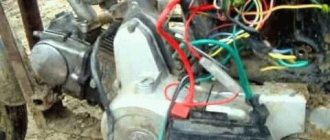
Installing BSZ on a motorcycle
Installation on the motorcycle did not take long. The old ignition had already been removed. In its place I installed a plate with a Hall sensor and put the butterfly modulator in place.
I determined the places where the switch will be located (in my case, near the battery) and the ignition coil (under the front of the tank).
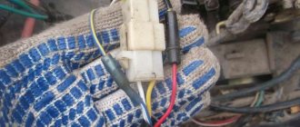
I used silicone wires from the coil to the spark plugs with automobile rubber tips (more than once they helped me out in heavy rain). I ran the wiring to the switch from the Hall sensor, having first lengthened it a little.
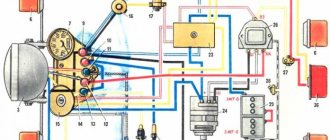
I connected the plus of the switch and the ignition coil to the standard wiring wire, which used to go to the breaker, and the minus of the switch to the housing, using the switch mounting bolt. The negative wire of the coil was connected to terminal No. 1 of the switch, as indicated in the diagram. He turned on the ignition and cranked the engine. There was a spark. All that was left was to turn on the ignition.
We set the ignition for the first time with the BSZ butterfly modulator.
We set the ignition almost as described in the manual, but with some adjustments due to the fact that we now have no contacts. The opening moment is determined by the spark on the spark plug when the modulator curtain passes through the Hall sensor.
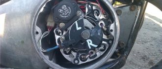
So. We set the crankshaft to mark P (early ignition, first mark, complete alignment of the arrow on the crankshaft and the marks in the center of the window). We unscrew the spark plug from the left cylinder, put on a high-voltage wire, and provide the spark plug with reliable ground. We move the weights as far as they will go and by turning the body of the plate with the Hall sensor we catch the moment of the spark. Having caught the position of the plate at which the spark jumps, we tighten it with three screws. We check again to make sure that the angle is not knocked down when tightening. The spark should jump at the moment of maximum divergence of the weights. The next step is to check the advance angle on the second cylinder. We rotate the crankshaft 360 degrees (a full turn) until the marks and marks P coincide. And we check for the presence of a spark at the point where the weights are completely separated. (We do not touch the plate with the Hall sensor) If a spark appears at the moment of complete divergence, then you can congratulate you, everything was done correctly.
DIY repair
Unfortunately, it is not possible to restore the ignition coil at home. If the problem is damage to the windings and the appearance of breakdowns, then the only repair method is to completely replace the windings. Imagine how long it will take to rewind the ignition coil - there are several hundred turns of wire on its primary winding, and several thousand on the secondary winding. Therefore, if the device is severely damaged, it is better to immediately purchase a new coil - fortunately, the part for domestic equipment is relatively inexpensive. The only case when you can temporarily restore full functionality of the ignition coil is if the insulation is damaged, which can be filled with varnish and wrapped with special tape.