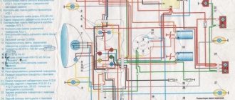
Our hero today is the legendary IZH, and as a bonus, the original and color wiring diagram of the IZH Planet 2, which is of interest to many lovers of Russian classics. It is needed both by those who are looking for preserved specimens for their collection, going out for rides a couple of times a year, and by those who prefer to acquire and restore the motorcycle of their youth for regular trips.
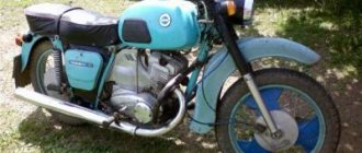
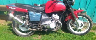
This is what the motorcycle looked like back in 1965
What is the value of this model
Such increased attention to the IZH Planet 2 model is caused by the fact that:
- in total, just over 246 thousand were produced;
- and there are few surviving copies left;
- which only increases its value among collectors .
According to Izhmash, only 246 thousand Planet 2 models were produced throughout the USSR.
Therefore, it was a great success to find preserved motorcycles in garages and sheds of villages and towns (as in the photo below). Moreover, if the previously discussed price has not changed, and the owners give you a bag of spare parts in addition, consider that you have hit the “jackpot” .
Fortunately, you can still find “live” IL with original parts. True, only in this state
Improving the standard system
The ignition system can be improved in other ways. To do this, you need to identify what problems there are with the wiring. They can occur in the primary circuit between the coil and the 12V battery or due to operating conditions. A visual inspection of the primary circuit can reveal problems with connections, contacts and the ignition switch.
If operating conditions are ideal, the primary circuit will operate with a 12V battery without failure.
But when dirt and dust get into the circuit, the resistance at the contact points increases, which entails a decrease in voltage from 12 Volts to 7-8 Volts. This voltage is not enough for a powerful discharge to appear in the secondary winding of the coil. As a result, a charge of less than 12 V appears on the spark plug, which poorly ignites the combustible mixture in the cylinders. Burnt contacts, oily spark plugs and batteries with a charge of less than 12 V further worsen sparking.
Standard wiring after modification
The following measures help solve these problems:
- The plug connectors are removed and each wire is soldered using traditional soldering and then insulated.
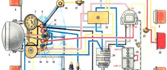
- An additional toggle switch is installed that turns off all consumers when the engine starts. Thus, the coils are supplied with 12 volt voltage from the battery (diagram 1).
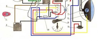
- Remake the ignition switch (IZ) (diagram 2). You need to take a wire and solder one end of it to the connector of lock 4, which is free, and the other to the positive terminal of the coil. The standard wire should be re-soldered from terminal 5 to terminal 6. After turning on this position of the key, power is supplied from the battery to the primary circuit according to a simplified scheme.
Thus, the changes made will make the electrical wiring of the IZH Jupiter 5 motorcycle more reliable and efficient.
Loading …
Recovery process
When the euphoria of the purchase wears off, a lot of questions arise regarding its repair and restoration with your own hands.
The main task of the new owners:
- Restore the electrical system - and there are no particular problems with this, since the electrical wiring of IZ Jupiter 2 and Planet of the second and third generations is identical and interchangeable;
- Starting the engine is a more difficult task due to the need to overhaul the power unit and the availability of spare parts;
- Return the motorcycle to its original appearance . It is also quite complex and, perhaps, the most painstaking work of the entire project.
Tip: Look at the publication - wiring diagram for IZH Planet 3, where all the differences and similarities between the models are described in detail.
The video below shows the restored models.
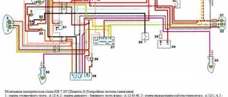
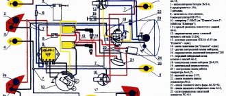
Note! For electrical work, you will need a wiring diagram for IZH Jupiter 2 - with the exception of the turn signals, they are identical. You can easily verify this by looking at the original photograph that was supplied with the factory instructions.
Factory layout for several generations of motorcycles
- Whether to switch to contactless ignition or change the voltage from 6 to 12V is up to you to decide.
- If you have such a desire, and you manage to get your hands on a native Izhevsk generator 281.3701 , then the replacement process will be much easier.
- The publication IZ Jupiter 3 wiring diagram will familiarize you with the details of the alteration.
central locking
Let's consider the process of restoring the central lock, since in most surviving models it is faulty.
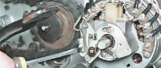
Appearance of the headlights and controls of IZH Planet 2
The difficulty is that finding the original lock is very difficult , almost impossible. Moreover, at 6V, since later the Izhevsk Motor Plant transferred all subsequent models to 12-volt equipment.
This is what the filling of the original 6V ignition switch looks like
Therefore, many motorcycle owners adapt parts from later versions of Planets and Jupiters.
The difficulty of installation in this case is as follows:
- Uncertainty about whether the lock will work;
- How to properly connect wires.
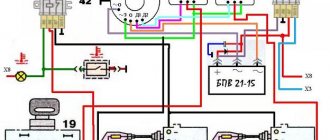
For reference: The photo below shows a tested scheme for installing a lock from Jupiter 2 to Planet 2. Everything is clear and understandable - connect and use.
Wiring diagram for IZH Planet 2 to the lock
Note! Parts from IZH are quite universal and fit many older motorcycles. For example, there is Java wiring with Izhevsk parts. But the IZH 2126 wiring diagram is unlikely to be useful for conversion - practically nothing from the namesake car fits the motorcycle.
Headlight
Many owners do not attach importance to adjusting the head light, believing that a working light bulb and intact glass are enough for “driving” during daylight hours.
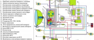
Using this scheme it will be easy to connect all consumers
In fact, this is not so, and adjusting the light is not only desirable, but also mandatory , especially since it can be easily done independently, spending no more than half an hour of personal time on it.
Scheme for adjusting the angle of luminous flux
Ignition adjustment
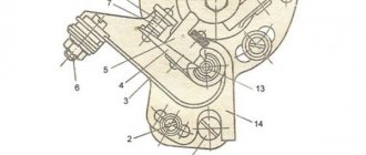
After replacing the generator, it is necessary to set the correct ignition timing.
To do this, we sequentially perform the following steps:
- We turn the crankshaft until the piston reaches top dead center (TDC);
- We lower it further down by 3.0 mm;
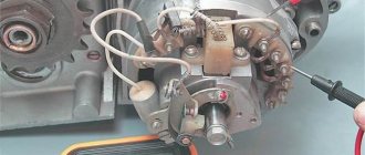
- We center the generator on the adapter washer so that the slot on the rotor is aligned with the inductive sensor;
- Using a feeler gauge, set the gap between the sensor and the slot. It should be 0.3-0.5 mm.
Connecting rod bushing size IZH Jupiter 5
The cylinder-piston group can be disassembled without removing the engine from the motorcycle. This, as a rule, has to be done to clean the piston and combustion chamber from carbon deposits, as well as to replace worn parts.
1. Remove the fuel tank.
2. Unscrew the exhaust pipe nuts and move the pipes away from the cylinder.
3. Remove the carburetor.
4. Remove the tip of the high voltage wire from the spark plug, remove the ignition coil, and unscrew the spark plug.
5. Disconnect the decompressor cable and unscrew the valve.
14 mm socket wrench
Unscrew the six nuts securing the cylinder head in a criss-cross pattern.
7. Remove the head.
14 mm spanner
unscrew the four nuts securing the cylinder to the crankcase.
9. Remove the nuts with spring washers.
10. Lower the piston to bottom dead center by rotating the motorcycle wheel or pressing directly on the piston. Remove the cylinder.
11. Cover the opening of the crank chamber with a clean rag to prevent foreign objects from getting into it.
12. Turn the cylinder over, install it on the studs and, carefully prying it with a knife, remove the gasket from the cylinder.
13. Similarly, remove the carburetor gasket (if it was not removed along with the carburetor).
14. Inspect the cylinder mirror. No scuffs, signs of heavy wear, grooves, enveloping of aluminum from the piston and other damage are allowed on it. This cylinder must be repaired or replaced.
You cannot grind the cylinder mirror with sandpaper and then polish it. The only possible processing is boring on a lathe to the repair size with mandatory subsequent honing. In this case, it is necessary to install a piston and rings of repair sizes (see below).
15. Using a scraper or knife, clean the cylinder exhaust windows from carbon deposits. Before this, carbon deposits can be softened with kerosene or acetone.
16. Check the condition of the threads in the spark plug hole. If the thread is damaged by more than a third in height, replace the cylinder head.
17. Similarly, inspect the thread of the hole for the decompressor.
If necessary, the cylinder head can be repaired by installing a liner in it. To do this, drill the spark plug hole to a diameter of 18.4 mm and cut an M20x1.5 thread in it. We grind a futor from brass or bronze (see figure) and, wrapping it into the hole, counter flare the lower edge. Such footwear is also available for sale.
Spark plug hole
18. Inspect the sealing band of the cylinder head. If unevenness is noticeable on the belt, grind the belt on a bench plate (with paste for grinding valves) or with an even, small abrasive stone.
19. Using fine sandpaper, clean the surface of the combustion chamber from carbon deposits.
20. It is useful to polish the combustion chamber with the finest sandpaper (with water), and then with GOI paste to a mirror shine. This way there will be less carbon deposits on it.
21. If the piston rings are to be replaced, they can be removed by breaking them. Otherwise, carefully place strips cut from a plastic bottle under the rings and remove the rings from the piston.
When using the old rings later, we mark them so that they can be installed in their original places during reassembly.
22. Using snap ring pliers or round nose pliers, squeeze and remove the piston pin snap rings from the piston. Do not compress the rings excessively to avoid permanent deformation.
23. Using a hammer, knock out the piston pin through a suitable mandrel (it’s easier to do this with two people).
24. Remove the piston.
25. We clean the piston bottom and ring grooves from carbon deposits (you can use a piece of an old ring). It is recommended to first soak the piston in acetone. It is also recommended to sand with fine sandpaper (with water) and polish the piston bottom (including a new one) with GOI paste, so less carbon deposits will be deposited on it.
26. We check the condition of the mating parts: cylinder, piston, piston rings, piston pin, bronze connecting rod bushing. The gap between the piston and cylinder, measured with a feeler gauge at the center of the piston pin, should not exceed 0.3 mm. The piston should be free of burrs, traces of melting, cracks and other damage. The surface of the piston pin must be free of traces of bronze, burns and heavy wear. A pin lubricated with engine oil and inserted into the upper head of the connecting rod should not feel any play. The finger should not enter the piston freely, but under light blows of the hammer. This is necessary in order to ensure working clearances between the pin and the piston when the parts heat up. The bronze bushing of the upper head of the connecting rod should also not have severe wear or signs of scuffing.