Video text
Today we will talk about a generator, and as you probably already guessed, instead of the standard one, I plan to install a generator from a tractor with a power of 1000 watts!
I bought it from an oppositionist named Sergei Krasnov. Sergey has a special contact group dedicated to the G-700 and G-1000 tractor generators, which he converts for Ural and Dnepr motorcycles. For those interested, here is the link to the group: https://vk.com/kilovat_uralAnd Sergei also has a separate topic on these generators on Oppzit.ru: https://oppozit.ru/post_83671.html
But, despite the fact that the G-1000 generator from a tractor has already been adapted for installation on Ural and Dnepr motorcycles, it cannot be simply installed))
Time code for the convenience of people installing such a generator on a Ural motorcycle: 1:27 Checking the generator for functionality 3:21 Review of the G-1000 generator, what are its advantages 4:52 Preparing the crankcase for installing a new generator 9:27 Removing the gear from the old generator 11:07 Installing the gear on the new generator G-100013:26 Adjusting the generator, adjusting the gap on the gears of the generator and camshaft16:10 Beautifying and polishing the generator17:44 Final installation of the generator on the gasket using sealant18:45 Connecting electrical wiring to the new generator
The fact is that the original 150 Watt generators of our motorcycle are weak and quite often fail, but the new generators are all Chinese and the opposition does not favor them. But the converted generator from a tractor, adapted to work on our motorcycle, has proven itself very well. In addition to the fact that it is many times more powerful and works more durable, it has several more advantages, such as: - this generator is self-excited, which means , that now you can start a motorcycle from a pusher, even if there is no battery at all. - the relay regulator is already built into the generator itself, which allows you to get rid of some of the wires and the standard relay, thereby making it possible to make a more compact and aesthetically pleasing arrangement of electrical wiring.________________________
ABOUT THE CHANNEL “SANYA CHETODEL”___________________________
As you might guess, they called me that because I am constantly doing something. I really love working and creating things with my own hands. At the same time, I constantly force myself to learn something new and unknown. For example, in these videos I am repairing an old Ural motorcycle, on which, based on the results of the repair, I plan to go on a trip to Crimea. This motorcycle will not only receive a complete overhaul, but will also undergo some tuning. I talk in detail about everything I do with the motorcycle in the playlist “Ural Motorcycle Repair”
Replacing a motorcycle generator with a more advanced 1000 or 750 watt.
Generator from tractor.
Heavy motorcycles in the domestic motorcycle industry are equipped with weak G 424 generators, designed for a maximum current of only about 15 amperes and a power of only 150 watts. In addition, they are too unreliable and often burn out, since the quality of workmanship, to put it mildly, has no idea what the word quality means. I’m generally silent about six-volt generator models; many call them flashlights, since the body diameter and luminous intensity are the same as those of ancient battery-powered Soviet flashlights.
And only recently, on more modern Ural Volk and Voyage motorcycles, they began to install 500-watt generators. And until they began to be replaced by Japanese generators from the Denso company, these generators either burned or their housing cracked at the attachment point. Generators from the Japanese company Denso, specially manufactured by this company for Wolves, Voyages and some Sollo models, are quite expensive and only 500 watts, which may not suit some fans of proper adult music.
Many owners of older Ural or Dnepr motorcycles install generators also from Japanese companies, but from cars. They still need to be found in working condition at a car disassembly and at a reasonable price, and if something burns out (they don’t like short circuits), then you will need to look for a Japanese part (relay, rectifier or winding), and as you know, Japanese spare parts are not cheap, even such common consumables as electric brushes.
I propose installing a three-phase generator from a tractor on the opposed engine - 462.3701, which does not have washable brushes at all; they are not provided for by the design. In addition, it has a power of 750 watts, and its new, more modern twin, which recently went on sale and has the same dimensions, has a power of 1000 watts.
Its main advantage over Japanese generators is the cheapness of spare parts (for example, a charge relay costs about $3), although in seven years of operation nothing on my motorcycle has ever burned out. Another advantage of this generator is that it can be bought literally for pennies at the nearest tractor brigade or in a special vehicle fleet, where you can also purchase a package of spare parts just in case - a rectifier unit BPV - 23 - 50 and an electronic voltage regulator Ya112B, an excitation coil and stator winding.
This generator was installed on almost all Soviet tractors, and on different tractors the difference was only in the diameter of the drive pulley. The main task when installing this generator on a boxer is: replacing the pulley with a drive gear, attaching it to the engine using a specially machined adapter, and connecting the electrical wiring.
By the way, the cover bodies need to be modified with a milling cutter, adding oval holes for cooling (see photo above), since the cooling impeller is removed along with the pulley and without these ventilation holes the generator will be a little hot in the summer. This is done naturally by disassembling the generator completely. Disassembly is also necessary to modify the shaft.
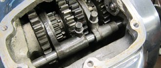
First, I machined the shaft to fit the gear from K 750 on it. This gear has fewer teeth, which means the rotation speed will be higher than with the Ural or Dnepr gear, and this is important. With a gear from K 750, the generator charges already from idle speed, but with other gears with a large number of teeth, charging begins only after medium speed.
But it's not that. The gear from a six-volt cacique has a very thin wall in the area of the key. Having seated and clamped the gear, I assembled and installed the generator on the motor. During the trip, I turned on all consumers to check: music at 600 watts, three headlights (300 watts), emergency lights, dimensions and lighting. The generator easily coped with such a load and still charged the 61-amp battery, but the gear did not - it simply tore and opened in the area of the key, like a book, due to the thin walls.
Having made my conclusions, I immediately took this gear to a milling machine friend I knew and ordered a gear with the same profile and number of teeth as on the Cacique one, but in the area of the key there is much more body, for a tapered fit. According to this cone in the new gear, they made me a new generator rotor shaft, since the old shaft was machined to a smaller diameter (for the K750 gear).
You could, of course, buy a new Cacique gear and press a metal ring onto it in the area of the key, but since I had the opportunity to find steel for ST 12 XN 3 A gears and make a new one (see photo on the left), for a tapered fit, I did this did.
In addition, with the Kasikova gear, the rotor shaft turns out to be painfully thin after grooving.
This option A is more complex and, in my opinion, the most reliable, but at the very bottom of the article there is a drawing of the shaft and gear of option B, which is simpler. As a result, despite the large number of consumers on my motorcycle, I have been riding with this generator for seven years and have never had any more problems.
Making an adapter.
For the adapter, it is advisable to use a stainless steel blank (I used titanium) with a diameter of 115 mm and a thickness of approximately 40 mm, so as not to bother with chrome plating if it is sharpened from “black” steel. In addition, any stainless steel has sufficient strength for these purposes, unlike aluminum.
There was a drawing of the adapter on the Internet, and in general it was not bad (the bottom photo of the adapter with a shaft for the Dnieper gear), but I didn’t like that the oil seal rubs along the diameter of the gear. In the drawing shown below, the oil seal rubs along the smooth rotor shaft and wears out less, since the shaft has virtually no runout (unlike the diameter of the gear) and has a smaller diameter at the point of friction. And there is no need to put a sealing washer on the sealant under the gear nut.
The blank is turned on a lathe to a diameter of 112 mm and a protrusion with a diameter of 70 mm is machined on the front side. Next, the future adapter is clamped by this protrusion in the lathe chuck, but with an offset of 5 mm. Only after this can you grind all the internal diameters indicated in the drawing. This offset is necessary to adjust the gap between the generator gear and the camshaft gear.
After turning, we give the part to the milling machine, you need to use an 11 mm cutter to select oval holes for the generator mounting studs, and then use a cutter to select selections (in the shape of a crescent) for the 17 mm nuts that secure the generator (see photo of the picture at the very bottom). Diameter C by 35 mm is the outer diameter of the oil seal that I bought, but you can buy a 30 or 28 oil seal, it doesn’t matter, and according to this diameter, machine the oil seal seat in the adapter. The internal diameter of the oil seal for the rotor shaft is 17 mm.
When the adapter is ready, you will need to connect it to the generator housing. To do this, you need to drill holes in the adapter with countersunk holes for M6 bolts securing the generator housing and adapter. But here you should take into account an important nuance - on the body of the front cover of the generator, which will be connected to the plane of the adapter, there are holes for ventilation (after all, there used to be a cooling impeller there). So, before drilling, we make a test connection between the cover and the adapter and mark with a marker on the adapter the four drilling points that do not coincide with the ventilation holes.
In the picture at the very bottom these holes are approximately shown (4 holes for countersunk holes). The second nuance is that it is necessary to take into account when drilling these holes, where the pins (M5) that tighten the generator housing will be located when the adapter and generator are assembled. They should not interfere with turning the generator around its axis when adjusting the gap. Ideally, the top pin should be at the very top, and the other two should be on the sides of the generator, just below the middle.
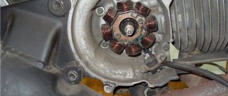
After drilling holes in the adapter with a diameter of 6 mm, and in the front cover of the generator 5 mm, an M6 thread is cut into five millimeter holes in the cover for mounting bolts with countersunk mounting. Now, before assembling the adapter and generator, you need to remove all unnecessary things from the generator body. At the back and front covers of the generator, we cut off the mounting ears and sand the cut points.
The front cover needs to be turned on a lathe to remove the protruding edge (but I did this using a grinder). We remove and throw away the triangular cover for mounting the front bearing; instead of it, an adapter will now hold the bearing. I polished the rear aluminum cover, and polished and chromed the front steel cover (see photo above), but before that I had the ventilation holes milled.
Now you can dock and assemble the generator with the adapter, and then tighten the covers with three M5 studs. During assembly, it happens that the screws securing the excitation coil may rest against the adapter and interfere with assembly. It doesn’t matter, they can be sharpened a little. Before docking and assembling the adapter and generator, do not forget to press the oil seal into the adapter. After assembling the generator, all that remains is to install it on the engine crankcase and naturally it will not fit without modifying the engine crankcase in place.
On the Dnieper, the “hump” on the crankcase where the camshaft runs should be ground off. But don’t overdo it, grind the aluminum little by little with a grinder, constantly checking the fit with a generator. The rear aluminum cover of the generator should also be slightly sharpened from below. Ideally, the generator should lie with its body on the ground area on the crankcase, but should not interfere with turning it when adjusting.
In the Urals, the camshaft “hump” is slightly smaller, but here you will have to unscrew the interfering nut securing the oil pump axis and order a turner a new flat nut with a countersunk counter. On six-volt boxer models, you will have to work longer with an angle grinder on the crankcase, but installing this generator on these engines is quite possible.
The only thing left to do is connect the generator to the motorcycle's electrical wiring. To the + terminal of the generator, connect the wire from the positive terminal of your motorcycle battery, and keep in mind that the wire must be of the proper cross-section (see top photo), especially if you have many consumers. In addition, now instead of a measly 15 A on your motorcycle, the current will now reach 60 A, and even more with a kilowatt. Connect a wire with a smaller cross-section to terminal D on the generator, stretch it and connect it to one of the terminals of the red generator control lamp. Connect the second terminal of this lamp to the ignition switch terminal, where on-board battery voltage appears when you turn the key. When you turn the key, the lamp will light up, and when you start the engine it will go out and at the lowest speed it will light up slightly. When the speed increases, the lamp will go out again, indicating that the generator is working and charging.
shaft option for the Dnieper gear.
In conclusion, I want to say that in addition to this method of driving a generator, there are also belt drives from a roller with a pulley, fixed in a standard place, and the generator is placed to the side towards the raindrops, and another method of drive from a flywheel using a multi-ribbed belt. All these methods, as always, have their advantages and disadvantages.
But I think the mounting and drive method described above in this article has the most compact and dust- and rain-protected advantage of fastening, and as you know, compactness and practicality on choppers have always been welcomed. In addition, when examined, whether technically or simply by strangers, it never occurs to anyone that something on my engine was made handicraft and that it was a generator from a tractor, and not from a foreign car.
If this article is useful to you, please share it on social media. networks by clicking the buttons below. Thank you.
RќСЂР°РІРёС‚СЃСЏ
Switching elements.
These include switches (high-low, turns, engine stop, etc.) as well as brake and neutral sensors and the ignition switch. You can easily “ring” them with a tester, finding out which contact group is not working.
As can be seen from all of the above, the wiring on Izh Planet is without any special secrets or complex elements, all its parts are easily diagnosed and repairs should not cause difficulties.
Now we advise you to watch the video, which shows in detail and clearly the assembly of the Izh Planet 5 circuit.
Checking the serviceability of the generator can be done on a motorcycle without disassembling the generator.
To carry out the work you will need a multimeter.
1. Place the motorcycle on the center stand or side stand.
2. Disconnect the battery by removing its fuse.
3. Remove the right cover of the power unit.
4. 6mm
unscrew the nuts securing the five “upper” wires of the generator. In order not to confuse the wires during subsequent assembly, we mark them or tie them with thin wire so that we get a cable.
Disassembly procedure
Lada Granta Liftback Logbook Clutch cable It all depends on the degree of damage to its parts. So:
- First of all, use a screwdriver or permanent marker to make a longitudinal mark on the body where the front and back covers separate. This will make it easier to assemble the generator in the future.
- We press the three spring-loaded latches on the plastic protective casing of the rectifier unit and remove it.
- Using a Phillips screwdriver, unscrew the two screws securing the voltage regulator and lift it up. Then remove the terminal of the appropriate wire from the regulator terminal and carefully remove the regulator completely. Electrically removable brushes are replaced along with the unit.
- Using a size 8 spanner, unscrew the three bolts connecting the rectifier unit to the annular terminals of the stator windings. We carefully move the conclusions to the sides. Remember the location of the thrust and insulating washers on the removed bolts. Now, using a Phillips screwdriver, unscrew the screw securing the noise suppression capacitor to the housing. Disconnect the appropriate wires. We remove the block itself and the capacitor. Using a 10 mm socket wrench, unscrew the two nuts of the contact bolts of the generator and take them out together with the spacer and insulating sleeve, and release the capacitor tip. It is worth noting that wear (or damage) of brushes is the most common cause of malfunction of the generator.
- Using a size 8 wrench, unscrew the 4 bolts holding the rear and front covers of the electric generator together. We push them apart with a face screwdriver and remove the back cover along with the stator winding.
- We remove the stator from the cover, having previously marked it with a mark of their relative position.
- If the front bearing needs to be replaced, remove the generator pulley. To do this, use a 22mm socket wrench to unscrew the nut securing the pulley to the rotor shaft, carefully holding it with pliers or wedging the rotor with a screwdriver. Do not damage the impeller blades, which are made of thin metal.
- Carefully remove the pulley, washers and spacer bushing.
- We return the nut to the rotor shaft, screwing it flush with the end of the armature shaft. Using a rubber hammer, knock the rotor (armature) out of the cover.
- If it is necessary to replace the front bearing, then to remove it, we clamp the front cover by the mounting ear in a vice, the jaws of which are covered with special pads made of soft metal or lined with fabric. Using a mandrel, press out the bearing.
- To replace the rear bearing, secure the armature (rotor) in a vice with pads and remove the rear bearing using a universal puller. If you don't have a puller, use two slotted screwdrivers. 8 nuts are placed under them as supports for lever screwdrivers.
- Removing the slip ring block. First of all, we remove the protective casing (cross) of the rotor contacts from the armature. Then we move these contacts to the sides and remove the slip rings from the rotor.
This completes the disassembly of the electric generator of the VAZ-2110 car. If any part breaks down, it must be replaced with a new one or, if possible, repaired. The generator is assembled in the reverse order.
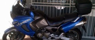
Motorcycles Ural and Dnepr
D12
DD everyone!
It’s a trivial question, actually, but I’m tired of it already. The point is this: we have a Ural-650 engine and a standard 6-volt generator with a gear. We proceed according to the manual: insert the gene, turn back (see from the commutator side) until it stops, turn the knee twice, turn the generator to the left by 3 millimeters according to the marks on the crankcase-housing of the generator, fix it, start it. There is a squeal of gears. Okay, I think I didn’t answer enough. I turn left again. I have a smaller squeal that turns into knocking. I turn further to the left - there is no squeal, but the roar is such that the Belarus tractor is an example of the quiet operation of a mechanism. Total - either a squeal, no knock (or not audible behind the squeal), or no squeal, but a strong knock is heard. The third condition (acceptable noise) is absent as a class. What's the rake? Thanks in advance! manowar,
judging by the description, heavily worn
D12
Where?
The bearings in the gene were replaced (which is why it was removed). axl
REMOVE THE GENERATOR AND LOOK AT THE CAMSHAFT GEAR, WEAR OF THE TEETH, AND EVEN THEIR PRESENCE.
AND THEN I HAD SUCH CRAP ON THE M-62, I TOOK OFF THE COVER OF THE JUNCTION BOX, AND HALF OF THE TEETH ON THE GEAR WAS MISSING. DID YOU FORGET TO PUT LUBRICANT IN THE BEARINGS IN AN HOUR? D12
So, let me clarify.
The generator has been rebuilt. The bearings were replaced (both) just in case. They are stuffed with Spectrol lubricant (similar to lithol, but higher temperature). The gear has been inspected and slobbered on all sides. The teeth are all there. There are no chips. The only drawback is minor irregularities on the working surface of the teeth. Sits tightly on the shaft and without wobble (by eye). After assembly (on a press, not with a hammer), rotation “by hand” by the gear is easier than with a new generator and without jamming. There is a slight unevenness in the rotation force, but I think this is due to the brushes. I checked the “electric motor” - it’s spinning! (I didn’t measure the current). Here's all the data. D12
Yes, the teeth on the camshaft gear are also all in place and without chips!
Sharapov
should just be put gear forward
Misha_B
And if you start it without genes, will there be any knocking or squealing?
D12
Without genes - normal operating noise...
ALGUNIN
and your rotor does not touch the stator by any chance, try and see if it could be
Misha_B
Could the rotor shaft be bent?
If you used a hammer when the bearing was removed? Kudray
just turn it carefully with the engine running.
finder
recipe for getting rid of squealing - remove the rear casing of the generator and use it as a jar for bolts so that it doesn’t look like Carlson and fray the gas hose; remove the fan and use it in some capacity..... then we get rid of the runout of the gear teeth - by centering the generator... whoever says that I’m an asshole, let him think first….
I had this device that blocked out even the exhaust (far from quiet) with its noise - the whole thing started making noise/clattering on the way from Maly...... in general, its shaft was bent due to something or something, but the usual methods no longer helped, after these manipulations, no sounds remind me of the existence of the generator... PS it produces electricity PPS strange, right? MadSkull
I had the same crap: With the alternator there is a squeal, without it it’s normal, The reason is extreme wear on the timing gears - look at the gap between them and you’ll understand everything.
D12
Thanks everyone!
I’ll dig further... (although I’m reluctant to remove the front cover...) D12
And here’s a follow-up question: should the generator gear be taken with a file, and how easily?
Otherwise, there is a suspicion that the nails are harder. PS: I took the gear from Sokolniki in the basement... ALGUNIN
What kind of file are you not using, of course, the hardened one should be
D12
Clearly.
So, again a leftist... bigzver
The whistling of the generator may also be due to this: the generator is pulling a certain load. If you overdo it, it becomes more and more difficult for the generator to rotate, so a sharp whistle may appear, very similar to the whistle of an unlubricated bearing. I advise you to check the network load. Maybe this is why the generator is noisy...
Checking the power of the generator on a motorcycle, without load.
This test does not require uninstalling the generator. With the motorcycle engine NOT running, disconnect the terminal going to the generator, the easiest way to find this terminal is by following the wire coming from the generator, disconnect the first terminal (3 thick yellow wires in insulation usually come from the generator and go through the entire electrical network of the motorcycle).
Set the tester to Volts – V measurement mode.
Start the engine, without choke, but the engine should only be warmed up a little for safe starting (this is clearly marked in the service book!).
Now, keep 5000 rpm on the tachometer (each motorcycle has its own value, but the principle is the same), now measure the voltage between the generator terminals.
For clarity, see the diagram:
In our example (Suzuki Hayabusa GSXR 1300 motorcycle), the voltage at 5000 rpm should be 65 Volts.
Replacing the piston group in a chainsaw or trimmer
Repairs of this level must always be balanced. How to correctly install rings on a two-stroke piston In installing rings on a piston. In such small engines operating at high speeds, replacing the first piston, which is burned out or jammed, does not give a long result and, if necessary, you need to change the entire piston group. Therefore, you need to consider whether to continue to use this saw or purchase a new saw.
If it is a professional model, then such repairs are worth carrying out, but if it is an old household model like a Husqvarna 40 and it has worked for more than ten or twelve years, it is not profitable to repair it. Because its repair will cost the same as purchasing a new saw, albeit not a Husqvarna, but a PARTNER P350XT CHROME, costing 165, will definitely be enough. Moreover, such saws are sold by Husqvarna, since PARTNER is its subsidiary.
But if you still decide to repair a chainsaw or trimmer, then you need original spare parts, which are not cheap. If the engine is used correctly, the first repair may not occur soon and only the piston ring or rings will have to be replaced, depending on the model. But if the saw jams, then it is necessary to change the entire piston group - the cylinder, piston and rings.
It should be noted that Husqvarna 136/141 chainsaws have a service life of approximately 500-600 operating hours, Husqvarna 340/350 - 1000-1200 operating hours, professional chainsaws have a service life of at least 2000-2500 operating hours, subject to strict adherence to the operating instructions. In fact, you cannot rely on these figures, since the actual resource may differ significantly, both up and down. But approximately we can say that semi-professional saws work 3-4 times longer than amateur ones, and professional ones up to 10 times or more.
Of course, nothing lasts forever, but it’s one thing if you change the piston group after many years of operation and it has worked its hours and has fully paid for itself, but another thing is that this saw was filled with, for example, only gasoline, without oil, and it jammed. This saw has to be repaired, since all other parts are normal.
Many companies deliberately inflate the cost of spare parts so that new models can be purchased. For chainsaws and trimmers, for example, from Stihl, spare parts are available in a larger range than for Husqvarna. Therefore, when choosing a specific model, find out how things are with spare parts. RVT
How to properly install rings on a two-stroke scooter piston
There is nothing complicated about installing rings on the piston of a two-stroke scooter, as well as a four-stroke scooter, and many people know this. But most scooter riders who have only recently acquired such equipment have no idea how to replace the piston on a scooter, how to correctly install the rings on the piston, where the arrow on the piston should point, and much more. In this lesson, I will tell you how to properly put the rings on the piston and assemble the piston in place. Since we have already talked about four-stroke engines before, here we will talk only about two-stroke engines. So, our piston is worn out and requires replacement. The rings and piston wear out first, and usually only those need to be replaced. If the piston is severely worn, it is necessary to bore the cylinder. It is also bored when the piston jams in the cylinder, forming deep scratches on the walls of the latter. There is nothing wrong with this, and if your new cylinder has been properly bored (which will only cost about 10), it will need a repair set of rings with a new piston. Such rings are marked 0.25. The second boring is 0.5, respectively, etc. to one. After purchasing a piston, it needs to be assembled. In the kit, as a rule, you will find the piston itself, two compression rings, a third thin corrugated ring (more on its purpose later), a piston pin and two piston pin retaining rings
Generator G-424
To understand the principle of operation of the generator and relay regulator, a little theory.
Electric generator G-424 is a three-phase machine, with electromagnetic excitation. Generates alternating current. The VGB-2A rectifier converts current into direct current. For normal operation of an electric machine, a relay-regulator PP-330 is required. The job is to regulate the voltage of the motorcycle's on-board network so that it does not exceed 14 volts.
The G-424 generator is not able to work with a discharged battery. To start the engine and increase to 2400 rpm, the motorcycle runs on a battery. Only after this threshold is exceeded does the electric generator operate in self-excitation mode.
Generator G-424 is PROHIBITED to be turned on without load!
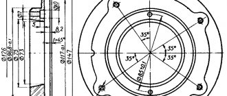
Generator circuit G-424: 1 - cover; 2 — oil seal; 3 - rotor; 4 - stator winding; 5 - terminal block; 6 — back cover; 7 — shield assembly; 8 - rectifier block; 9 - fan; 10 — protective casing; 11 - bearing.
Troubleshooting the generator
The method for determining the malfunction was as follows (I tried several methods, since replacing the relay regulator did not help):
Indirect determination of generator performance
This method does not allow you to accurately determine the malfunction of the generator, but it can still be used to determine whether the generator is “dead,” or there is still hope and the cause of the malfunction lies elsewhere.
Disconnect the wire from terminal “Ш” on the generator. And we apply + from the battery to this terminal, bring the wrench to the generator body, it should be magnetic, not much, but it is noticeable. If it is magnetic, then the rotor winding is working properly. Turn it off.
We connect a 12 volt lamp to the “+” terminal on the generator, and the other end of the lamp to ground. And we connect “+” from the battery to the “Ш” terminal. And we turn the engine with the kickstarter, the light should light up. If this happens, then the generator is working.
In my case, the light was on, I changed the relay-regulator, but the battery still did not charge, and when the engine was running, the red battery charge control light did not go out.
Cleaning and testing the generator G 424
- I removed the generator, unscrewed the back cover, pulled out the brushes - the wear was within normal limits, they were checked with a multimeter.
- Using the probes through the windows for the brushes with a multimeter, the armature rang - “it rang”, there is no short circuit to the generator housing.
- I unscrewed the rectifier and it “ringed” like diodes, i.e. In one direction the arrow should deviate, I change the polarity, the arrow does not deviate. Those. the diodes are not “broken”, as they should be.
- I rang the stator windings - everything is normal, there is no short circuit to the housing.
Everything is in perfect order, the generator should be in good working order, so I didn’t completely disassemble it. But there is no charge. Therefore, I began to understand the operation of the relay regulator and look for the reason for it.
Restoration, testing, connection of the G424 generator
This is the kind of generator you want to see on a motorcycle.
And this is what the generator of a Ural or Dnepr motorcycle usually looks like when it has been in operation.
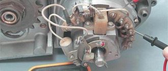
- Let's get started. We disassemble the generator, clean the covers, degrease and prime. With this process everything is clear and does not cause any difficulties.
After the generator is disassembled, you can check the condition of the bearings, oil seal, and brushes. It's better to change it right away. Remove the bearings either with a puller or carefully cut them with a grinder.
Check: Winding on the rotor (armature). Winding on the stator. Checking for breakdown, ground, interturn short circuit and open circuit can be carried out by “continuity” using a multimeter. You can also check the diode bridge with a multimeter. More on this later.
Theory of generator operation and performance testing.
The figure below shows a diagram of the generator assembled (on the left) and on the right, disassembled into three parts.
Diode bridge, Stator winding (non-moving part) connected according to a star circuit and Armature (aka rotor, what rotates), brushes are just feed contacts.
Troubleshooting or testing should be divided into three parts: checking the stator winding, checking the armature winding, checking the bridge.
But first we should remind you how it all works.
Operating principle of three-phase alternator:
1. Excitation voltage is applied to the rotor winding using graphite brushes through contact rings.
2. Rotating inside the stator winding, the rotor winding through which current flows induces an EMF in the stator winding. Faraday's law. There are 3 stator windings and they are out of phase by 120 degrees.
3. The alternating voltage is removed from the stator windings and converted to constant voltage by a diode bridge. In the diagram and graph below it is clear how alternating current is rectified into direct current by diodes.
In a three-phase alternating current generator, there is no permanent magnet; instead, there is an electromagnet in the form of one winding on the armature, which, when voltage is applied to it, “excites” generation.
This is what the assembled generator looks like with a circuit diagram superimposed on it.
Below is a diagram of connecting the generator to the on-board network with a relay regulator of a new three-pin model and an old one.
The difference in the above diagrams is in the relay regulator. In the circuit with the VAZ regulator, it is not necessary to connect the generator control terminal. The regulator itself has status diagnostic indicators.
The generator in the on-board network of a motorcycle is controlled in the same way as in a car.
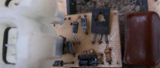
A modern relay regulator is built on semiconductor elements and there is no relay in it as such; instead, an electronic key is organized, which is either open or closed. Also, the regulator relay contains a measuring element that is capable of measuring the generator output voltage and checking it with its reference voltage. At the moment when Uout. — the voltage at the generator output will be greater than Uop. - voltage support, RR will remove power from the excitation winding and generation will stop.
Checking the motorcycle's charging.
- We take a tester and set it to measure constant voltage (if there is a gradation of measurements, set it to 20 V). We measure the battery with the motorcycle not running. A fully charged battery is 12.8 - 12.9 volts (if less, it is advisable to charge the battery so that further measurements are correct, and also check the battery - you can read how to do this in the article: How to check the battery.)
- If the battery is serviceable and infected, we proceed to check the charging of the motorcycle. We measure the voltage on the battery with a tester, with the motorcycle running (idling, without consumers turned on: lights, heated handles, etc.), the voltage should be 13-15 volts. If the motorcycle charging test does not meet the criteria, move on.
- We turn on only “natural consumers” (lights), the voltage should be at least 12.8 volts (ideally, about 13.5 volts). If less, something is wrong.
- We turn on all consumers (additional equipment), if the voltage drops below 12.8 volts, try raising the idle speed to 1000 - 1100, the voltage should be at least 12.8 volts. If it is smaller, the generator does not pull all consumers (additional equipment) and may burn out.
- We give the gas 3000 - 4000 revolutions, the voltage should rise to 13 - 15 volts with all consumers turned on. On some motorcycles, the voltage rises to a maximum at 3500 -4000 rpm, and at higher rpm it drops, but not more than 13 volts (this is due to increased load at high rpm: the injectors begin to consume more power (they are open almost all the time), this is normal ). If less, something is wrong.
Heavy class motorcycles URAL, DNEPR | Topic author: Alexander
Adapter for car generator
Alexander (Amaria) Will be standing nearby. Generator from UAZ
Ilnur (Sable) What about your generator?
Alexander (Amaria) I want to install a generator from the car because... it is more powerful and there will be no problems with light
Lyolya (Chaya) set from a tractor to 1kW 150W
Lyolya (Chaya) only a lathe is needed
Generator stator 281.3701 for IZH motorcycles
The stator is installed on the right half of the engine crankcase and secured with three bolts. The frame is made of special sheet steel. It has 18 tooth-shaped places for winding phase windings. The phase winding is made of one solid wire with a diameter of 0.9 mm and is wound on six teeth. Each tooth has 20 turns of copper wire wound around it. There are six teeth in total on the winding, so 120 turns are wound. There are three such windings. The connection of the windings is made with a star. The terminals of the phase windings are connected to the terminals of the comb.
The generator stator is covered with an aluminum alloy cover. There are special places on the cover and threaded holes where the carbon brush holder is installed. A breaker with a capacitor to produce a spark. Special comb for connecting wires.
Generator G-414 of the Ural motorcycle.
The first production of motorcycles used six-volt electrical equipment. Accordingly, the generator generated direct current at the required voltage. It is installed in a special hole in the engine crankcase and secured with a tightening tape. Adjusting the gear engagement as on the G-11A is described above.
1 – anchor; 2 – winding; 3 – bandage; 4 – collector; 5 – cover; 6 – rear bearing; 7 – cover; 8 – output; 9 – shields; 10 – coil; 11 – body; 12 – front cover; 13 – protective washer; 14 – front bearing; 15 – oil seal; 16 – key; 17 – castle nut.
Selection of piston to cylinder
Device Features
Completing and assembling a piston with a connecting rod for a VAZ engine
The piston is made of aluminum alloy and coated with a layer of tin to improve run-in. The piston skirt is oval in cross section and conical in height. Therefore, it is necessary to measure the piston diameter only in a plane perpendicular to the piston pin and at a distance of 52.4 mm from the piston bottom.
The hole for the piston pin is shifted from the axis of symmetry by 2 mm to the right side of the engine. Therefore, for proper installation of the piston into the cylinder, there is a “P” mark near the hole for the piston pin, which should be facing towards the front of the engine.
Since 1986, repair size pistons for all engine models have been manufactured with an outer diameter increased by 0.4 and 0.8 mm. Until 1986, pistons of the following repair sizes were produced: for engines 2101 and 2103 - with an increase of 0.2; 0.4 and 0.6 mm; for 2105 and 21011 - with an increase of 0.4 and 0.7 mm.
Piston rings are made of cast iron. The outer surface of the upper compression ring is chrome plated and has a barrel shape. The lower compression ring is of the scraper type (with a groove along the outer surface), phosphated. The oil scraper ring has slots for oil removed from the cylinder and an internal coil spring (expander).
The piston pin is steel, tubular in cross-section, pressed into the upper head of the connecting rod and rotates freely in the piston bosses.
The connecting rod is steel, forged, with a split lower head in which the connecting rod bearing shells are installed. The connecting rod is processed together with the cover, so during assembly the numbers on the connecting rod and the cover must be the same.
The calculated gap between the piston and cylinder (for new parts) is 0.05-0.07 mm. It is determined by measuring the cylinders and pistons and is ensured by installing pistons of the same class as the cylinders. The maximum permissible gap (if parts are worn) is 0.15 mm. Note. The piston diameter is measured in a plane perpendicular to the piston pin, at a distance of 52.4 mm from the piston crown. According to the outer diameter, the pistons are divided into five classes (A, B, C, D, E) every 0.01 mm, and according to the diameter of the piston pin hole - into three categories every 0.004 mm. The piston class (letter) and piston pin hole category (number) are stamped on the piston bottom.
If a used engine has a gap exceeding 0.15 mm, then it is necessary to re-select the pistons to the cylinders so that the gap is as close as possible to the calculated one.
Spare parts include pistons of classes A, C, E. These classes are sufficient to select a piston for any cylinder during engine repair, since pistons and cylinders are divided into classes with a slight overlap of sizes.
Assembly. Before assembly, fit the pin to the piston and connecting rod. For new parts, the class of pin holes in the connecting rod and piston must be identical to the class of the pin. For used parts, for proper mating it is necessary that the piston pin, lubricated with engine oil, enters the hole of the piston or connecting rod by simply pressing the thumb and does not fall out of it. Replace the finger that falls out with another one of the next category. If a third category pin was inserted into the piston, replace the piston pin and connecting rod.
Assembly of the connecting rod and piston group is carried out in the reverse order of disassembly. After installing the piston pin, lubricate it with engine oil through the holes in the piston bosses. Install the piston rings in the following order. Lubricate the piston grooves and piston rings with engine oil. Orient the piston rings so that the upper compression ring lock is at an angle of 45° to the piston pin axis, the lower compression ring lock is at an angle of approximately 180° to the upper compression ring lock axis, and the oil scraper ring lock is at an angle of approximately 90° to the axis locking the upper compression ring. Install the lower compression ring with the groove facing down. If the ring is marked “TOP” or “TOP”, then install the ring with the mark facing up (towards the piston bottom). Before installing the oil scraper ring, check that the joint of the spring expander is located on the side opposite to the ring lock.
Procedure for checking the serviceability of the alternator on your motorcycle.
All information was taken from the motorcycle service book and is absolutely not made up. To check the serviceability of the generator on a motorcycle, you will need a multi-meter (tester); you can purchase it at any radio-technical store or electronics store.
In general, all work on electronics and electrical work (for example, checking the serviceability of the same regulator relay on a motorcycle can only be done using a multi-meter) requires a multimeter.
This test does not require removing the alternator from the motorcycle. With the engine NOT running (once again, DO NOT start the motorcycle during this test!).
Disconnect the terminal going to the generator, the easiest way to find this terminal is by following the wire coming from the generator, the first terminal and disconnect (3 thick yellow wires in insulation usually come from the generator and go through the entire electrical network of the motorcycle).
Set the tester to resistance measurement mode – .
Now, according to the diagram below, measure the resistance between each winding, and then between the winding and the ground (black wire to the frame, red we measure the resistance in the terminal).
On each motorcycle, the generator has the same value between the windings, but these values may differ from one motorcycle model to another; in order to find out what the resistance value is on your motorcycle model, look in the service book of your motorcycle.
In our example (Suzuki Hayabusa GSXR 1300), the resistance should be 0.2-0.2 (Ohm).
On the other hand, if you do not have a service book for your motorcycle model and the resistance value cannot be determined, then remember the following:
– if the value on one winding differs from the other two, it must be replaced.
– if the resistance value is different on all windings, the generator on the motorcycle is clearly not working properly
– also be sure to visually assess the condition of each generator winding (you will need to remove the generator cover, and then change the gasket under the generator cover, so if there is resistance, everything is in order - do not remove the cover!).
Is it possible to increase the power of a generator that is 150 watts?
Maybe you can redo it anyhow,
read in the articles, as long as someone doesn’t reprint them in Moto. You need to increase the bias current, you can simply increase the efficiency by replacing the diodes.
what if we increase the rotor speed? Play with the drive a little?
and who is stopping you? There are gears like this for sale.
I agree with replacing the diodes - the voltage drop across them will decrease, but the maximum output current will not increase. Increasing the excitation current is a double-edged sword (the winding will burn out anyway - not sooner, but later) CAN JUST REVIEW THE ENERGY BALANCE: put a normal lamp with standard characteristics in the headlight, and not Chinese (Taiwanese, Turkish.) 110 W crap, which The light is shining in the wrong direction, by the way this applies to all consumers, not just the headlights. Choose a good RR, remove all the snot from the wiring (otherwise the losses sometimes reach 20W). And everything will work well, and there will be enough power. And in order to increase the power significantly, and not by 10-20 W, as Manowar suggests, you need to redo the generator at the design level.
for armored train
: I’ll repeat it again - it’s not about power, but about impact! Replacing the diodes will allow you to produce the same power, but at lower speeds. Should I explain this to each individual individually? 150 watts on a motorcycle is enough for the eyes. the main problem with a 150 watt generator is not low power, but the fact that to create a positive balance of electric energy you need engine speeds of about 1700-1800 (ignition and lamp power supply is 60 watts) due to the fact that when driving in the city you often have to stand and maintain such It is not possible to constantly rev the engine - there is a risk of overheating. and the main work should be carried out not to increase power, but to shift its characteristics to the region of low rotation speeds. An increase in the bias current even by 2 times will not cause much heating of the rotor winding.
where did you see me suggesting increasing power? and at the design level there is already 500 watts.
Can you give me a link where this article was written?
Source
Factors influencing the price of the service - repair of a motorcycle generator in Nizhny Novgorod
It is common knowledge that the cost of car repairs depends on several aspects. Among them are the following:
- cost of spare parts (original, China, alternative manufacturers);
- personnel qualifications;
- level of equipment of the service station (availability of painting booths, lifts, special tools and equipment, etc.).
For example, the price of the service - repair of a motorcycle generator in Nizhny Novgorod will also depend on factors such as the age, make and model of the car. We are confident that car services will compete for your order and offer the best conditions. The centers have a system of discounts for regular customers.