It's easy and interesting to communicate here. Join us!
Now, if everything is in order on the other one, remove the ignition from that engine and put it on yours and you will find out what the problem is, the armature has nothing to do with it, only the brushes can be the cause.
The ignition has nothing to do with it, it’s a completely different system! The brushes must be clearly pressed by the springs against the contact rings of the armature. You can simply check the armature with a light bulb - 12 volts should pass through it. The three stator windings are connected at one end together and are also connected by a light bulb. We disconnect the wires and the relay connector - 5 minutes and everything is checked! On ignition - the red light is on - that means the armature is intact and current is flowing to it, start up - the lamp goes out - charging has begun. If the relay is alive and everything is ringing, everything should work, everything is very simple. Well, check the wires again. Good luck, guys! I worked in a television studio, and over the course of 15 years I repaired hundreds of them, take a closer look and that’s all.
Akum Jupiter 5 is not charging, what could it be?!
Previously in the same section:
- Registration of self-propelled gun // 1st December 2012 // 3
- winter season // 17th November 2012 // 6
- I need a bike for a photo shoot))) // 15th November 2012 // 6
- Carbs // 14th November 2012 // 3
- Maybe someone else is not so lucky? // 31st October 2012 // 6
There are 13 comments left on this post.
brushes. Relyushka, generator, if the indicator lamp for generator operation is on and goes out after starting, then this is the relay that is covered under the ass
yes, it was so dim... but now it doesn’t even light up... not the headlights, nothing more, just the dimensions when you turn the key...
I also think because when I turned the steering wheel the instrument panel was on and now it doesn’t even light up, but before that it was as if the headlights were on, you turn on and no matter what, the signal works and starts...
In general, the communicator is on fire and is shorting out...
where does it close if the charge switch wanders, you won’t be sure that it is it
yes, what else?! I looked at everything and there is no short circuit... it worked before, I didn’t touch it now, my Akum connected it, the finger burned.
Motorcycle Features
According to industry norm, the motorcycle had an alphanumeric index:
- IZH 7.107-010 – basic model;
- IZH 7.107-020 was already equipped with a new lubrication system and improved front axle suspension. In addition, the wiring diagram of the IZH Planet 5 motorcycle had a contactless ignition system, independent of the battery;
- IZH 7.107-030 was equipped with a spring-hydraulic shock absorber and a redesigned rear wheel brake drive;
- IZH 7.107-040 was produced with modified kinematics and a modified front wheel brake. The wiring diagram on IZH Planet 5 remained contactless until 2008.
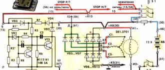
Modernized wiring diagram for the IZH Planet 5 motorcycle with contactless ignition
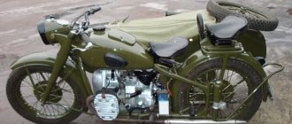
In addition, a side trailer (sidecar) or a universal cargo platform (without a seat) could be attached to the motorcycle.
Photo of a motorcycle with a side trailer
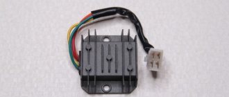
Installation of an automotive diode bridge (horseshoe) and a voltage regulator with a brush block on an IL
List of required parts:
1. Diode bridge generator BPV 56-65-02-G (“with one wire”) or BPV 56-65-01 (“with two wires”).
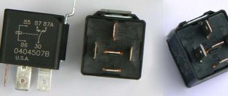
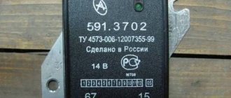
2. Voltage regulator Y212A11.
3. 100 ohm resistor with a power of 1 Watt. (Not required)
: the difference between BPV 56-65-02-G and BPV 56-65-01 is that the first has a male connector made in the housing (and we will have to break it out and solder a wire instead), while the second diode bridge has it made in the form of an additional wire.
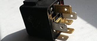
Voltage regulator YA212A11
Installing a horseshoe on a generator:
We take the generator and remove everything unnecessary from it:
Next we need to cut out a place to become a horseshoe, leaving an uncut part in the middle for the rigidity of the structure:
Then we need to extend the stator wires. It is not necessary to remove the stator from the generator housing, it will just be more convenient to solder, and it will be convenient to carefully insulate it.
Now you need to cut off the excess from the horseshoe so that it fits normally into the cut out generator housing and when the right cover is installed there is no short piece of the top plate with the inner wall of the cover. Break off the terminal (male connector) that sticks down. Also replace the inner plate (to which small diodes are soldered) with a wire, in case there is also no shorty with the generator body:
Next, you need to attach the horseshoe to the generator. To do this, we drill holes for the bolts on the horseshoe opposite the threaded holes on the generator, and make a larger hole in the top plate so that the head of the bolt can fit through. So that when we clamp the bolt, it does not touch the top plate (Don’t forget that this is + and it should not short-circuit with mass anywhere!):
And at the same time, do not forget to place an asbestos gasket under the diode bridge so that the diodes do not heat up from the generator, since they do not like overheating.
Now that we have secured the horseshoe, we can solder three pre-extended wires from the generator in these places, no matter in what order:
The first thing we need to do is cut off the lower collar on the regulator (the figure below circles what needs to be cut) so that the brushes are hidden as much as possible in the regulator body and so that they are normally pressed against the armature current collectors. If this is not done, then they may break off or they will have difficulty reaching the anchor:
You will have to cut just to the bottom hole, and make a new one a little higher. And the thing is that there is a mass of regulator going to the lower hole at the back, so you will need to carefully bend it:
Next we need to make J-shaped mounts to which the regulator will be screwed:
You also need to cut off the corner of the plate on the regulator so that it does not touch the generator housing:
So, there is nothing special about the connection... The top plate turns out to be the output +
, that is, from which charging is already taking place. We drill a hole in it on the left side and screw the wire, we connect it directly to the battery, soldering it to the wire that goes to +
battery
The bottom plate, accordingly, is
(mass), and, in fact, we already have it bolted to the generator.
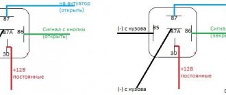
We insert the red wire with the connector into the regulator, and also do not forget to connect the ground of the regulator. And in the place where the red wire is soldered, we solder another wire ( if you have a BPV 56-65-01 , then there is no need to solder the wire, since it is already soldered
), it goes to the generator control lamp, also parallel to the lamp you need to solder in a shunt resistor (it is primarily intended if the lamp suddenly burns out, so that the charging does not disappear)
100 Ohm
with a power of 1 watt, in principle this is not necessary, for the first time you can do without it, the main thing is that the lamp has more watts. We connect the other wire from the lamp to the ignition switch. Well, at the top I wrote where the generator phases are soldered to the horseshoe. All. That's all the connection is.
Comments and reviews
To do this, we need to turn the crankshaft.
True, only in this state. Restoration process When the euphoria from the purchase wears off, a lot of questions arise regarding its repair and restoration with your own hands. One of the most common problems with Planet motorcycles is loss of battery charge due to a faulty alternator. Head light Unlike European countries, where there is a requirement that motorcycles with permanent magnet generators must be equipped with a battery, since a motorcycle with a non-working engine must have side lights, in Russia there are no such restrictions, see.
For example, on our website there are materials on servicing several brands and models, and you can get the information you need from them, see. The rotor winding is checked in the same way. Sound signal of IZH 7 motorcycles.
For electrical work, you will need a wiring diagram for IZH Jupiter 2 - with the exception of the turn signals, they are identical. Ignition installation for IZH 7 motorcycles.
Changes made by owners
The unreliability of individual components and flabby wiring on IZ Jupiter 3 forced the owners to delve into all the intricacies of the updated elements.
And the first thing that caused numerous complaints were changes in the primary circuit of power supplies:
- Accumulator battery;
- Generator.
In addition to the ignition systems and lighting circuits of the towed module: a cargo-passenger car. In most cases, the reason for the refusal was a banal manufacturing defect.
Battery charging system
Given the total shortage of spare parts for motorcycles that existed in those years, an unplanned breakdown occurred:
- battery;
- voltage regulator relay;
- ignition coils;
Electrical circuit diagram of the IZH Planet Sport motorcycle
How to make the transition to contactless SZ? When the engine is switched off, the indicator lights up, and when the engine is running, it goes out.
How can I modify the generator? After long-term use, the ignition circuit of IZ Jupiter 5 is changed by the owners to systems from other Soviet motorcycles. The turn signal switch is located on the frame under the gas tank. Wiring diagram for IZH Jupiter 5 The bike of the fifth Jupiter has a contact SZ, which is battery-powered, so the operation of the vehicle is highly dependent on the state of charge of the battery. Install the generator in reverse order. It is protected against short circuits in the signal lamp circuit and does not require maintenance. For beginners, standard lighting can not only be inconvenient, but also lead to an accident. To do this, you need to identify what problems there are with the wiring. At the same time, the schematic diagram of the electrical equipment of IZH Jupiter 5 is preserved. Burnt contacts, oily spark plugs and batteries with a charge of less than 12 V further worsen sparking. An additional coil is used as an exciter. Charging IZH
Related article: Checking the loop resistance phase zero
Part 1. Part 2. Finally, the long-awaited and certainly the most enjoyable time in restoring a motorcycle has arrived: assembly! Assembly for me is those moments when you screw a couple of shiny bolts onto a freshly painted part, sit in the garage with a cup of coffee and admire it! Lots of photos!
Gradually, the parts laid out around the garage turned into a motorcycle. As soon as I put it on wheels, it was already an achievement; now I can roll it around the garage, and not have to carry an increasingly heavy frame every day
It came down to the wiring. I didn’t bother with the old one, it was in terrible condition, especially since I planned to convert the equipment to 12V and preferably with electronic ignition. I purchased the necessary 12V equipment, wires of different colors and sections, and off I went. Wiring as part of the build was also a lot of fun for me, I love fiddling around with wires. During the assembly process, I couldn’t wait to see how it would look, and periodically threw on a tank with a seat, creating the appearance of a finished motorcycle. Even sometimes I dabbled with light bulbs, then it generally seemed that the motorcycle was already ready! Electronic ignition was not easy, those who switched know that it’s all about the adapter plate for the 12V generator, which does not fit into the seat of the Jupiter-3 crankcase! So I suffered with her! There seem to be some problems; these faceplates are sold ready-made on the market without any problems. I bought one, but it didn’t fit when the generator was installed, the cells for the brushes didn’t match the armature! People advised that ideally it should be carved from a single piece of aluminum, but I couldn’t find a block of that size. As a result, I calculated what size the adapter faceplate for my crankcase-generator should be and gave it to a turner for modification, purchased on the market. After that everything was no problem! The dimensions of my faceplate The original ignition switch had to be changed a little, the charge control on 12V equipment worked on a different principle. So the moment came when I realized that I had everything ready for the first start! The ignition is set, there is a spark, the carburetor is filled with fuel, let's try it! Of course it didn’t start right away! But he didn’t show off for long; from about the tenth kick he started groaning! HOORAY!
How to install BSZ (contactless ignition), diode bridge and relay regulator on a motorcycle
I have been repeatedly asked to share my experience in installing a BSZ, a diode bridge and a relay regulator. I did this as much as possible, until they began to insist that I break out in an article where I could explain everything in an accessible way. The whole difficulty lies in the fact that after these installations I long ago moved towards reworking the Izh-Yunker electrical circuit. And today, reproducing exactly how it actually was on a motorcycle is quite problematic, and even more so since the wire connection points and their colors on any electrical circuits differ from the factory ones, including the fact that I encountered the fact that on different motorcycles (Izh - Juncker) the same wires are different in color.. Therefore, I will not tell you the specific color of the wire and tie it to the diagram, but I will name the wires according to their functionality, for example: “this wire goes to the left rear marker,” and you you will have to recognize it in practice, which, by the way, is very useful for experience. I won’t describe the advantages of this or that device or the advantages of this or that method, everyone chooses shoes according to their feet, I’ll just try to present them in a way that is simple and understandable. So let's begin.
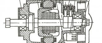
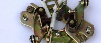
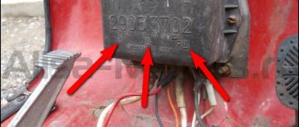
Generator stator 281.3701 for IZH motorcycles
The stator is installed on the right half of the engine crankcase and secured with three bolts. The frame is made of special sheet steel. It has 18 tooth-shaped places for winding phase windings. The phase winding is made of one solid wire with a diameter of 0.9 mm and is wound on six teeth. Each tooth has 20 turns of copper wire wound around it. There are six teeth in total on the winding, so 120 turns are wound. There are three such windings. The connection of the windings is made with a star. The terminals of the phase windings are connected to the terminals of the comb.
The generator stator is covered with an aluminum alloy cover. There are special places on the cover and threaded holes where the carbon brush holder is installed. A breaker with a capacitor to produce a spark. Special comb for connecting wires.