The relay clicks, but the ATV does not start
How to properly connect the fuel pump on a scooter after repair or replacement, we will consider further.
read more » A common problem is that a scooter or moped starts with a kickstarter, but refuses to start with an electric starter. Let's consider all possible causes and methods for eliminating them. read more "
Of the trio of Japanese manufacturers, Suzuki scooter carburetors are perhaps the most capricious. Let's look in detail at how to properly connect carburetors to the engines of the following scooters read more "
Causes of heat seizure: read more »
For the average scooter user, the easiest way to test the voltage regulator is with the scooter engine running and can be done within one minute. Let's look at how to do this correctly using a regular multimeter. read more "
The scooter clutch assembly is equipped with bearings, ball, needle, and their combinations, which are the most common. Let's take a closer look at how to replace clutch bearings on a scooter. read more "
If, when you press the brake lever of the hydraulic brake system of the scooter, the brake caliper cylinder does not receive the necessary force to adequately press the brake pads to the disc and stop the scooter at lightning speed while moving, it is obvious that air has entered the system read more »
Safety while driving is ensured, among other things, by informative and precise steering. Only correct adjustment of the steering column can ensure smooth turning of the steering wheel without jamming or vibration. read more "
This material will be useful to all owners of a wonderful scooter - Honda Lead 90 with an HF-05 engine. The material contains all the data, technical characteristics, nominal and limiting parameters for the engine read more "
Replacing the drum brake pads of a scooter is necessary if the linings on the pads are worn out, the pads themselves are defective, and also in some cases when the operation of the scooter with the current pads is unsatisfactory due to the poor quality of the pads. So, let's look at the process of replacing the brake pads of a scooter drum brake. read more "
In the design of a scooter you can find a large number of oil seals of various sizes, designs and densities, but they all have the same task - to maintain the tightness of the connections read more "
Let's look at a simple example of how to use available tools to check the performance of the clutch within a few minutes and, if necessary, replace it. read more "
This material is intended for beginners. Here you will learn how to inspect the variator and rollers of the Honda Lead AF-20 scooter at home, using ordinary improvised tools that every scooterist has. read more "
To check the condition of the rings and piston, it is necessary to disassemble the engine, namely, remove the cylinder head and the cylinder itself. Only direct measurements and inspection can definitely determine the degree of wear and most effectively help take the necessary repair measures. read more "
It is very easy to check the cylinder of a four-stroke scooter yourself for the need for further repair. This includes only two operations - checking the plane of the cylinder surface that is in contact with the head and checking the geometry of the working surface of the cylinder. read more "
How to Check the Starter Relay on an Alpha Moped
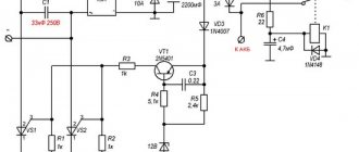
ELECTRONICS OF ALPHA AND DELTA MOPEDS Due to the fact that more and more owners of devices with engines of the 139FMB type and lights at recess are faced with six-coil generators (replacing the motor or preferably a more powerful generator), there is a need to write this article. First, let's figure out what the differences are. The picture shows a diagram
The electrical equipment of the mopeds under consideration consists of a source and consumers of electronic energy, auxiliary devices and an electronic network. Electrical equipment ensures timely ignition of the working mixture in the engine cylinder, operation of lighting devices and
The most popular scooter in Russia and Ukraine is the Viper Active. And here everything is very simple, a decent appearance, an established network of product suppliers, a reasonable price and a truly bassy and beautiful exhaust sound, which is sometimes misleading, and creates the memory that the Viper Active is installed on
about all the electronics on a moped. In this video we will tell you in general terms how the wiring in the bike works. Enjoy watching. Wiring on Chinese mopeds Alpha, Delta and its repair
Drawings and photos of electrical circuits of mopeds. I sketched out a few things for anyone who needs to figure it out! There are also 2 types of voltage regulator: 4-pin and 5-pin. The diagrams show only 4-pin. Generators for them are different. You can find a generator for a 5k regulator by the fact that it does not have windings
1 Ignition module (CDI) 2 Ignition coil 3 Spark plug 4 Alternator 5 Voltage regulator 6 Battery 7 Fuse 8 Starter 9 Start button 10 Start relay 11 Tachometer 12 Ignition switch 13 Brake light 14 Transmission neutral indicator 15 Instrument panel backlight 16 Headlight
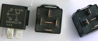
Starter relay for Chinese motorcycles and scooters - alternative replacement
The purpose of the video is to save the nerves and money of the owners of Chinese motorcycle equipment to check
your relay
maybe from the link.
How to check the starter relay on a scooter
Main tasks of the relay
. Problems with the electric starter itself are not considered.
The “Delta”, “Alpha”, “Leader” and “Mustang” mopeds use a 12 V battery with a capacity of 2.5, 3.0 or 5.0 A/h (Table 6.1). Inside the case, the battery is filled with a chemical reagent and electrolyte. Battery maintenance involves periodically checking the level and density of the electrolyte.
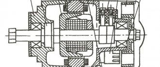
The source of electricity for mopeds is a generator (magneto), the rotor of which is mounted on the left axle of the engine crankshaft. Flywheel type generator, alternating current, with excitation from permanent magnets. To diagnose a generator, special equipment is required. Disassembly
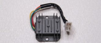
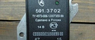
One of the main elements of the moped's electrical system is the voltage regulator-rectifier. The appearance of the voltage regulator-rectifier is shown in Fig. Rice. 6.6. The voltage regulator-rectifier performs two functions: it ensures the voltage in the moped network within the range of 12.0-14.5
Method for checking the voltage regulator of a scooter
Chinese scooters are designed in such a way that their relay-regulator, which is also called a voltage regulator, often burns out. The voltage regulator is an electrical circuit with 4 terminals for connecting to the scooter's electrical network.
A malfunction of the voltage regulator leads to very disastrous consequences:
At first, the instrument panel backlight lamps and the central low/high beam lamp burn out. This happens due to the fact that the voltage from the generator is not limited to 12 volts, which leads to the lamps receiving an increased voltage of 16 to 27 volts and higher. The voltage supplied to the lamps fluctuates and depends on the engine speed. Even at idle, the lamps shine so much that they blind, although they should shine at half their maximum brightness.
If you do not remove the malfunction of the voltage regulator and leave everything as is (many do this - they just drive without lights), then over time the battery will fail because its charging voltage exceeds the permissible one. If the voltage regulator is faulty, the battery receives a voltage of more than 15 volts, while the standard charging voltage should be between 13.5 - 14.8 volts. All this leads to the fact that the battery begins to leak - acid begins to penetrate through the valves. This is noticeable to the naked eye. And although when the normal charging mode is restored, the battery restores its operation, its service life is sharply reduced.
Also, if the voltage regulator is faulty, the battery stops charging correctly and loses its capacity. Therefore, it is not possible to start the scooter with the button. You have to start it from kickstarter.
I think it’s now clear how important it is to change a faulty voltage regulator on a Chinese scooter.
How to check the voltage regulator on a scooter? It is best (and most reliable) to do this without dismantling the voltage regulator itself. We will need at least some kind of multimeter with a voltmeter function. Any ordinary DT-830 or similar will do. What should be done? It is necessary to measure the voltage at the output of the voltage regulator.
How to check the charging relay, voltage regulator
In this video I will show you how to check
two-phase
relay voltage regulator
, also called charging relay...
How to check if the relay regulator on a motorcycle is working?
How to check
Is the bike's alternator working? — .
All measurements were carried out on a Chinese scooter ABM Storm L ZW50QT-16.
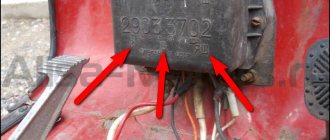
To get to the relay-regulator, unscrew the front fairing in which the central headlight is installed. We find there on the frame a box with 4 terminals: red, green, yellow and white.
We put the scooter on the stand and start it. After some time, the engine operation stabilizes at idle. Next, measure the voltage between the green and red wires. We set the multimeter in DC voltage measurement mode to the limit of 20V. Here's a look at how you can do it.
The display should display a voltage of about 14.6 - 14.8 volts, as in the photo. This is normal, standard voltage.
Then we need to measure the voltage that goes to the lighting lamps. The voltage to the central high/low beam lamp is not constant, but alternating (pulsating), so we switch the multimeter to the 20V alternating voltage measurement mode. On the multimeter that I used (Victor VC9805A+), you need to press the DC/AC (Alternating Current) button to do this. After this, we measure the voltage between the green and yellow wires. We simply move the probe from the red to the yellow wire, since the green wire is the common wire in the scooter’s electrical network.
The multimeter display should show a voltage of around 12 volts. It showed 11.4 - 11.6 volts. This is normal as the scooter is idling. If you have an assistant, you can ask him to accelerate a little to increase the engine speed and, consequently, the voltage from the generator. In any case, the voltage should not change much and should be around 12 volts.
This was a voltage measurement at the output of a working voltage regulator (relay regulator).
Now let’s see what a voltmeter shows when measuring the voltage at the output of a faulty scooter voltage regulator.
Rules for operating a moped
The service life of a moped depends on maintenance. Care comes down to following the rules recommended by the manufacturer.
The main ones include:
If the electric starter on a scooter does not work, then there is always a kick starter that will help out. But using a manual starter is not always convenient. Therefore, in this article we will find out why the starter on a scooter does not work. The electric starter is powered by a battery and passes through a special relay. Therefore, the first reason why the starter on a scooter does not work is the battery . It may have malfunctioned or simply run out of power. If you hear a spinning sound when starting the scooter through the electric starter, then the problem is with the battery. In this case, check the contact at the terminals . If it's not the contacts, it's the battery. If it is simply discharged, then it is enough to start the scooter with a manual starter and drive several tens of kilometers. This is enough to slightly charge the battery. If it still does not charge, then most likely it is faulty and needs to be replaced.
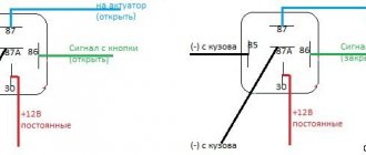
But if you hear the starter relay click when you press the starter button, then the problem will be more complicated. In this case, you can find out what the problem is by using the diagram:
Using this diagram, you can easily determine why the starter does not work on a scooter . This can be done quite quickly, since it does not require much effort and there are only a few things to check.
If you have any questions , leave them in the comments and you will receive an answer as soon as possible.
Now you know why the starter does not work on a scooter.
Scooter alternator voltage test
If you have a multimeter, you can check the output voltage of the generator. A good battery will have a voltage greater than its rated voltage level even if it is completely discharged and allowed to sit for a few minutes or if it is in storage.
If the battery does not recover above its rated voltage level within a few minutes after being discharged, this indicates a faulty or worn-out battery. When the battery is fully charged and its voltage is below the rated voltage level, this also indicates a faulty or worn-out battery. Good scooter batteries will return above their rated voltage level within a few minutes of starting the scooter.
Look for any burnt or melted wires or wire connectors on the speed controller. If any wires are burned or melted, the speed controller may be faulty. Smell the speed controller for any burning smells. If the speed control smells, it is almost always faulty.
Speed controller
If the ESC doesn't have burnt or melted wires and doesn't smell, it may still be bad. Check all other electrical system components around the speed controller and use the elimination process to determine whether the speed controller is working or not. Speed controllers are too complex to be easily tested. Using a professional diagnostic is the best way to determine whether the ESC is working or not. If all other components of the electrical system are fine, but the scooter does not work, this indicates a faulty speed controller.
You can also watch some videos
Voltage regulator or as it is also called relay regulator
This piece of electrical equipment is very important and the longevity of the battery and other electrical appliances depends on it. The relay performs the function of a voltage stabilizer at the level that the generator produces, then this voltage goes to all the scooter devices that use it
If the voltage regulator was faulty or missing from the scooter, the voltage would jump and all the devices would quickly burn out. The regulator keeps the voltage within certain limits, preventing it from rising and falling too much, usually within the range of 12-14.5 volts. For example, incandescent lamps suffer significantly even from an increase in voltage of 2 volts.
The generator can produce 35 volts, and the regulator resets this voltage to 12 volts. To charge a scooter battery, you need direct current; it is the regulator that turns alternating current into direct current. Therefore, you need to look at the condition of the scooter’s voltage regulator very carefully so as not to cause trouble. One of the ways to understand that the relay regulator has failed is that the light bulbs quickly burn out. They themselves have a fairly high resource and durability, but at the same time they are sensitive to voltage drops. By the way, when starting the scooter from the starter, a strong surge in voltage occurs, which can also cause harm, but the regulator on the scooter again corrects this situation.
Different scooter manufacturers supply different relay regulators, since each model requires an individual one. Depending on the voltage regulator circuit, the connectors may also differ.
The voltage regulator relay on a Chinese scooter differs from the Japanese one even in the number of terminals. So, in Chinese there are 5 of them (dad), but in Japanese there are only 4.
But the general principle of operation of the voltage regulator is almost the same in all of them and performs the role of switching voltage using a powerful thyristor, turning on and off the voltage from the generator.
Regulator diagram on Japanese scooters:
How to check the starter button of a scooter?
A common cause of starter failure is the starter button. You yourself know what the quality of Chinese goods is, and if the starter of your scooter one day fails, it makes sense to check the button and, depending on the test results, move on, for example, to the starter relay, the starter itself, or go to the store for a new button.
To check we need:
In order to check the button, you must first remove it from the plastic steering wheel trim. The button sits in the casing on two side latches. Press the latches one by one with a screwdriver and remove the button.
The button is connected to the scooter's on-board network via a three-pin connector. There are only two contact wires in the connector: yellow and green, brown is not used. The yellow wire is positive and the green wire is negative. In scooters, the wiring is made according to a two-wire circuit, so there are two contact wires.
We disconnect the plug from the button, switch the tester to audio dialing mode, connect the tester probes to the side contacts of the button (the middle contact is not involved), press the button key and look at the tester:
As you can see, everything is very simple. By the way, in this way you can check the starter button not only of a scooter, but also of any other similar equipment, including an ATV, motorcycle, moped, or even a KAMAZ - it doesn’t matter.
Purpose of the voltage regulator relay on the VAZ 2106
As you know, the power supply system of the VAZ 2106 consists of two important elements: a battery and an alternator. A diode bridge is built into the generator, which motorists in the old fashioned way call a rectifier block. Its job is to convert alternating current into direct current. And to ensure that the voltage of this current is stable, does not depend on the rotation speed of the generator and does not “float” much, a device called a generator voltage relay regulator is used.
This device provides constant voltage throughout the entire on-board network of the VAZ 2106. If there is no relay regulator, the voltage will deviate abruptly from the average value of 12 volts, and it can “float” in a very wide range - from 9 to 32 volts. And since all energy consumers on board the VAZ 2106 are designed to operate under a voltage of 12 volts, without proper regulation of the supply voltage they will simply burn out.
Design of the relay regulator
On the very first VAZ 2106, contact regulators were installed. It is almost impossible to see such a device today, since it is hopelessly outdated, and it has been replaced by an electronic regulator. But to get acquainted with this device, we will have to consider the contact external regulator, since its example reveals the design most fully.
So, the main element of such a regulator is a winding of brass wire (about 1200 turns) with a copper core inside. The resistance of this winding is constant and is 16 Ohms. In addition, the regulator design includes a system of tungsten contacts, an adjustment plate and a magnetic shunt. There is also a system of resistors, the connection method of which can change depending on the required voltage. The highest resistance these resistors can provide is 75 ohms. This entire system is housed in a rectangular PCB body with contact pads for connecting wiring brought out.
Operating principle of the relay regulator
When the driver starts the VAZ 2106 engine, not only the crankshaft in the engine begins to rotate, but also the rotor in the generator. If the rotation speed of the rotor and crankshaft does not exceed 2 thousand revolutions per minute, then the voltage at the generator outputs does not exceed 13 volts. The regulator does not turn on at this voltage, and the current goes directly to the excitation winding. But if the speed of rotation of the crankshaft and rotor increases, the regulator automatically turns on.
The winding, which is connected to the generator brushes, instantly reacts to an increase in crankshaft speed and is magnetized. The core located in it is pulled inward, after which the contacts on some internal resistors are opened, and the contacts are closed on others. For example, when the engine is running at low speeds, only one resistor is used in the regulator. When the engine reaches maximum speed, three resistors are turned on, and the voltage on the excitation winding drops sharply.
Scooter starter malfunctions: identifying and fixing the problem
The presence of a starter in a scooter, unlike a car, is not mandatory. However, it makes life much easier for the driver, adding a little comfort while working. Everyone knows that the starter works thanks to the battery, and it consists of:
The principle of its operation is no different from any other starter, although some breakdowns may differ from the usual ones.
Why doesn't the starter work?
Initially, you need to exclude battery discharge from the list of possible breakdowns. If this were the case and the battery suddenly became low, you would hear a peculiar sound when you press the “start” button. This sound indicates that the starter is not engaged with the bendix and is running without load, idle. If you still hear this sound when starting up, do certain things:
In most cases, these points will help you solve the problem with your scooter.
However, there may be other breakdowns, which in themselves are considered more serious when compared to a dead battery. We are talking about audible clicks when the starter operates. This is a deeper problem and it is necessary to look for its causes.
Causes and solutions
Step 1: With the ignition on, try honking the horn. If everything worked out and you could hear a loud and ringing sound, everything is fine, you can start the engine. If the sound was very quiet or could not be heard at all, there were problems with the battery or power supply (recharge the battery, clean the terminals).
Step 2. When you press the engine start button, you hear the sound of the relay turning on. If yes, then try bridging the power terminals of the relay. If there is no sound, disconnect the relay from the power supply, and then use the wires to connect the battery and starter.
Step 3. Once you have connected the starter, it works fine. If yes, then you just need to replace the relay. If not, check the contacts of the start button, the wires from the starter, and replace all worn parts.
Motorcycle starter and its repair
The main starter malfunctions may be the following. When the starter is turned on, the traction relay does not operate and the armature does not rotate.
Causes:
- malfunction or complete discharge of the battery;
- severe oxidation of the battery pole terminals and wire tips;
- weak tightening of tips;
- disconnection or break of the traction relay wire on the starter or ignition switch side;
It is also possible that there is an inter-turn short circuit in the winding of the starter traction relay, a break or short to ground, a jamming of the traction relay armature, and no one can rule out a malfunction of the contact part of the switch.
When the starter is turned on, the traction relay is activated, but the armature does not operate or does not rotate intensively enough. The reasons may be:
- battery discharge;
- oxidation of the pole terminals of the battery and the tips of the connecting wires;
- loosening the fastening on the contact bolts of the starter traction relay;
- commutator burning;
- brushes hanging or excessive wear;
- break in the stator or armature winding;
- short circuit of the insulated brush holder of the positive brush to ground;
- short circuit between the collector plates;
- interturn short circuit in the armature or stator windings or their short circuit to ground.
Basic Concepts
In order to understand wiring, you need to understand a little about the types of current. A constant is one that does not change its direction and magnitude. Variable is one where the voltage and current change their value after some time, or the current flows in the opposite direction. Often direct current, as can be seen in the wiring diagram of the Alpha moped, is needed for light bulbs: headlights, turn signals, foot. There are models where the motorcycle is completely converted to direct current, but these are old models and they are quite rare.
Malfunctions
There is nothing special to break in the starter and all its malfunctions consist of wear, sticking of the brushes and contamination of the commutator, which often happens due to engine oil getting into the housing from the engine crankcase. It is worth noting that faults associated with commutator contamination and brush wear are typical for DC electric motors.
Worn brushes, as well as a dirty commutator, prevent the passage of electric current through the brushes to the lamellas of the rotor windings and therefore the starter stops working. In this case, to restore the functionality of the starter, we just need to clean and wash the commutator and replace the brushes with new ones or make them ourselves (more on that later).
Valuable advice
It is no secret that the insulation of the wires is made of cheap plastic and it is better to replace the insulation with rubber before it crumbles after a few rains. The two networks in Chinese motorcycles do not intersect, therefore, when disassembling the power supply of the on-board network of the electric starter, headlights, turn signals and stop, you should remember several points:
They all go into a big black rope. The colors are fixed and it’s easier to remember what they belong to than to have to decide for a long time where they come from and where they go. There are two main coils: under the steering wheel and next to the battery, under the shield. If next to the battery you can still determine what is coming from where, then under the steering wheel the wiring of the Alpha moped begins to resemble Narnia: everything is lost there and the colors change. Wiring from this point spreads throughout the motorcycle, providing power.
The secret to reassembling
To avoid the long and tedious hassle of installing the rotor into the housing, secure the brushes from moving out in their sockets with toothpicks, lubricate the rotor axles with some refractory grease, install the rotor in the housing and remove the toothpicks. This will make it much easier and faster, and most importantly, you won’t break or twist anything.
And one more thing: if after assembly the starter rotates in the other direction, do the following: unscrew the bolts holding the housing together and rotate the housing with magnets 180 degrees relative to the second half of the housing and the problem will go away.
Source
Wiring work
The large black wire connects: 2 yellow, green and red, where direct current flows. Red goes into the ignition switch, from which by turning the key you can close the system and make it work. On the reverse side, the harness goes to the console, where it is connected to the switches. If voltage has been lost, then you should look at the operation of this harness - does the voltage go out from the ignition switch into this black harness.
The second line serves to power the battery (black-red), pulse from the magnetic sensor (blue-white) and has ground (green). There is a lot of voltage going to the battery, and therefore you can only touch the wires with the engine off. If the question arises about how to connect the wiring on an Alpha moped if there are problems with this line, then you should pay attention to the armored wire - the large black wire that goes to the spark plug from the ignition coil. And a rather dangerous symptom allows you to suspect a break in the black-yellow wire: if the moped does not stall, but will work until the gas runs out. This wire turns yellow in the middle and goes to the ignition coil.
Electrics and electrical equipment of a scooter
Dedicated to all owners of Chinese scooters...
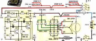
To begin with, I would like to present a wiring diagram for a Chinese scooter.
Since all Chinese scooters are very similar, like Siamese twins, their electrical circuits are practically no different.
The diagram was found on the Internet and is, in my opinion, one of the most successful, since it shows the color of the connecting conductors. This greatly simplifies the diagram and makes it more comfortable to read.
It is worth noting that in the electrical circuit of a scooter, just like in any electronic circuit, there is a common wire. On a scooter, the common wire is the minus (-). In the diagram, the common wire is shown in green. If you look more closely, you will notice that it is connected to all the electrical equipment of the scooter: headlight (16), turn relay (24), instrument panel backlight lamp (15), indicator lamps (20, 36, 22, 17), tachometer (18 ), fuel level sensor (14), horn (31), tail light/brake light (13), start relay (10) and other devices.
First, let's go over the main elements of the Chinese scooter circuit.
Egnition lock.
Ignition switch (12) or “Main switch”. The ignition switch is nothing more than a regular multi-position switch. Even though the ignition switch has 3 positions, the electrical circuit uses only 2.
When the key is in the first position, the red and black wires are connected. In this case, the voltage from the battery enters the electric circuit of the scooter, the scooter is ready to start. The fuel level indicator, tachometer, sound signal, turn relay, and ignition circuit are also ready for operation. They are supplied with power from the battery.
In the other two positions, the black and white wire from the CDI ignition module (1) is shorted to the housing (common wire). In this case, engine operation is blocked. In some scooter models, to block the engine, there is an engine stop button (27), which, like the ignition switch, connects the white-black and green (common, body) wire.
Generator.
The generator (4) produces alternating electric current to power all current consumers and charge the battery (6).
There are 5 wires coming from the generator. One of them is connected to a common wire (frame). The alternating voltage is removed from the white wire and supplied to the relay regulator for subsequent straightening and stabilization. The yellow wire removes voltage, which is used to power the low/high beam lamp, which is installed in the front fairing of the scooter.
Relay regulator.
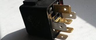
Regulator relay (5). People may call it a “stabilizer”, “transistor”, “regulator”, “voltage regulator” or simply “relay”. All these definitions refer to one piece of hardware. This is what the relay regulator looks like.
The relay regulator on Chinese scooters is installed in the front part under a plastic fairing. The relay-regulator itself is attached to the metal base of the scooter in order to reduce the heating of the relay radiator during operation. This is what the relay regulator looks like on a scooter.
In the operation of a scooter, the relay regulator plays a very important role. The task of the relay regulator is to convert the alternating voltage from the generator into direct voltage and limit it to 13.5 - 14.8 volts. This is the voltage required to charge the battery.
The regulator receives alternating voltage from the generator through the white wire to the relay. Also connected to the regulator is a yellow wire coming from the generator. It supplies the regulator with alternating voltage from the generator. Due to the electronic circuit of the regulator, the voltage on this wire is converted into a pulsating one, and is supplied to powerful current consumers - the low and high beam lamps, as well as the dashboard backlight lamps (there may be several of them).
Ignition circuit elements.
One of the most important electrical circuits in a scooter is the ignition circuit. It includes the CDI ignition module ( 1 ), ignition coil ( 2 ), spark plug ( 3 ).
CDI ignition module.
The CDI ignition module ( 1 ) is made in the form of a small box filled with compound. This makes it difficult to disassemble the CDI unit if it malfunctions. Although the modular design of this unit simplifies the process of replacing it.
There are 5 wires connected to the CDI module. The CDI module itself is located in the bottom of the scooter body near the battery compartment and is secured to the frame with a rubber clamp. Access to the CDI block is made difficult by the fact that it is located in the bottom part and is covered with decorative plastic, which has to be completely removed.
Ignition coil.
Ignition coil ( 2 ). The ignition coil itself is located on the right side of the scooter and is mounted on the frame. It is a kind of plastic barrel with two connectors for connection and a high-voltage wire output that goes to the spark plug.
Structurally, the ignition coil is located next to the start relay. To protect against dust, dirt and accidental short circuits, the coil is covered with a rubber cover.
Spark plug.
A7TC spark plug ( 3 ).
The spark plug turned out to be cleverly hidden on the scooter, and it can take quite a long time to find it the first time. But if we “walk” along the high-voltage wire from the ignition coil, the wire will lead us straight to the spark plug cap.
The cap is removed from the candle with a little effort. It is fixed to the spark plug contact with an elastic metal latch.
It is worth noting that the high-voltage wire is connected to the cap without soldering. The insulated stranded wire is simply screwed onto the screw contact built into the cap. Therefore, you should not pull the wire too hard, otherwise you can pull the wire out of the cap. This can be easily fixed, but the wire will have to be shortened by 0.5 - 1 cm.
It's not so easy to get to the spark plug itself. To dismantle it, a socket wrench is required. With its help, the candle is simply unscrewed from its seat.
Starter.
Starter ( 8 ). The starter is used to start the engine. It is located in the middle part of the scooter next to the engine. It's not easy to get to.
The starting of the starter is controlled by the starting relay (10).
The start relay is located on the right side of the scooter frame. The starting relay receives a thick red wire from the positive terminal of the battery. This is how the start relay is energized.
Fuel gauge and indicator.
The fuel level sensor ( 14 ) is built into the fuel tank.
There are three wires coming from the sensor. Green is common (minus power), and the other two sensors are connected to the fuel level indicator ( 11 ), which is installed on the dashboard of the scooter.
The fuel sensor ( 14 ) and indicator ( 11 ) are one device and are powered by a constant stabilized voltage. Since these two devices are spaced apart, they are connected by a three-pin connector. The positive supply voltage is supplied to the fuel indicator and sensor via the black wire from the ignition switch.
If you open the three-pin connector coming from the fuel sensor, the fuel indicator will no longer show the fuel level in the tank. Therefore, if your fuel indicator does not work, then check the connecting connector between the sensor and the fuel indicator, and also make sure that they are receiving power.
It is also worth remembering that the supply voltage is supplied to the sensor and indicator when the ignition switch is in the closed position ( 12 ). According to the diagram, this is the right position.
Turns relay.
Turn relay or breaker relay ( 24 ). Serves to control the front and rear turn signal lamps.
As a rule, the turn relay is installed next to the instruments (speedometer, tachometer, fuel level indicator) on the dashboard. In order to see it you need to remove the decorative plastic. It looks like a small plastic barrel with three terminals. When the turn signals are on, it makes characteristic clicks with a frequency of about 1 Hz.
After the turn relay, a turn signal switch ( 23 ) is installed. This is an ordinary key switch that switches the positive voltage from the turn relays (gray wire) to the lamps. If you look at the diagram, when the switch is in the right position ( 23 ), we supply voltage through the blue wire to the right front ( 21 ) and right rear ( 32 ) indicator lamp. If the switch is in the left position, then the gray wire is shorted to the orange one, and we supply power to the left front ( 19 ) and left rear ( 33 ) indicator lamp. In addition, in parallel with the corresponding indicator lamps ( 19 , 20 , 32 , 33 ), signal lamps ( 20 and 22 ) are connected, which are located on the dashboard of the scooter and serve as a purely informational signal for the scooter driver.
How to check, replace
Checking is carried out using a multimeter. This device is used in electromechanics and is sold in hardware stores. There are models without a sound signal - they do not differ in appearance, and therefore you have to ask the sellers. Without a sound signal or “ringing” it is inconvenient to constantly look at the panel, but it is possible to carry out the check. Sequentially, starting from the battery to the ignition circuit and generator, all the wiring of the Alpha moped is checked. The multimeter has two probes: red and black. Red ones need to touch the plus, and black ones need to touch the mass or ground.
Thus, the wiring of the Alpha moped is a complex and vulnerable place for this vehicle. However, this is exactly what will help toughen the motorcycle owner in the face of eternal breakdowns and make him a real ace in the electricity of his motorcycle.
How to Check the Starter Relay on a Chinese Scooter
How to check the starter relay on a scooter
Posted September 1, 2016
The main obstacles of the relay . Problems with the electric starter itself are not considered
Why is the pipe shit?
I disassembled my relay , unwinded the entire winding, re-wound it, cleaned the contacts, and now for the 5th year everything has been fine with the relay, my brain doesn’t work at all, there’s just no point in buying a new one, because there’s no guarantee of how long it will last enough again
I have a Skymoto Spider 50 scooter and this is the relay clicks and the starter doesn’t turn, but if you connect the direct wire from the battery, the starter turns and the relay has already been changed. What could be the reason.
Tell me, my starter turns but doesn’t turn, I can take a video and post it, what should I do? battery is charged
the relay clicks and the spark disappears?
I like and subscribe
Where is the starter relay on a Suzuki Adreas 110
storm 50, when the ignition is turned on, the starter does not work, the emergency lights do not work, turns in general as if there is no battery, it starts with the kick starter and everything works, what could be the matter. the fuse is intact
the scooter does not charge the battery how to find out the reason
On Glushak Shit Pipe!))) Well, you need to buy a multimeter.
I have such a problem, the scooter racer is generally Chinese, it won’t start from the starter , I took it apart and got to the relay in general there is a spark, but there is no “ whack, whack ”, the battery is charged, what could be the problem?
Thank you Krasava helped.
I have the following question: when you press the starter button, the relay just clicks once and the starter doesn’t turn, this happened rarely before, but now I just can’t start it from the starter ; I measured the voltage on the battery at 13.1 volts, but with the starter it starts normally.