Replacing a relay regulator on a motorcycle
Sooner or later, almost all owners of Ural or Dnepr motorcycles are faced with a battery charge problem.
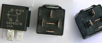
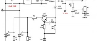
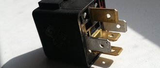
The standard relay-regulator type PP 330 eventually stops working correctly and needs to be cleaned or adjusted. Not every motorbike owner can competently perform these operations. Replacing with a new one is an option, but the cost of a new PP 330 is often quite high. Getting out of the situation, however, is quite simple. After all, you can install in the regular place of the PP 330 an electronic voltage regulator of type 121.3702 for 12V from a VAZ car, which is sold in any auto store, and its cost is several times lower than the PP 330. But for this you will have to work quite a bit with the wires. The electronic voltage regulator is installed in the standard place of the PP 330 with virtually no modifications. During the replacement process, it is necessary to additionally drill one hole in the mounting area of the regulator relay. You also need to replace the screw terminals on the wires that go to the PP with female connectors.
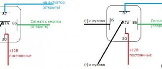
We connect the wire that went to the terminal (VZ) on the PP 330 (upper terminal) to the connector (15) of the electronic relay. We connect the wire that went to terminal (Ш) (lower right terminal for PP 330) to connector (67). We screw the ground wire to the metal base of the electronic relay (31) through the screw securing the housing to the platform. Two wires remain unconnected: LC - control lamp (lower left terminal) and “change” (middle lower terminal). For “lazy” motorcyclists, the conversion process can be considered complete; you just need to insulate these two wires and leave them hanging in the air, screwing them to the frame with something so that they don’t dangle. In this case, the battery will charge, but the alternator warning lamp on your motorcycle will not light up.
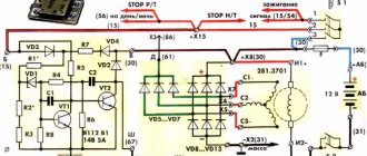
For those owners who are not satisfied with “half measures”, we continue the process. Together with the electronic relay regulator, you need to purchase a small relay of type RS 702 or (75.3777) with normally closed contacts from the auto shop. The RS 702 is remarkable in that when voltage is applied to the relay winding. the relay contacts open. This additional relay can be installed on one of the screws securing the electronic relay-regulator.
We connect the relay type RS 702 as follows. We connect the wire that went to the terminal (change) of PP 330 to connector (86). We connect the wire that went to the terminal (LC) to the connector (87). We dealt with the wires hanging in the air. We connect connector (85) to ground with a separate wire. We connect connector 30/51 to the wire that goes to connector (15) of the electronic relay, which is also positive from the ignition switch.
Scheme of URAL 4320 engine electrical equipment, gear shifting and braking system
The approximate location of the holes in the adapter is shown in the figure. Diagram of the URAL lubrication system The oil in the system is indicated on the general URAL lubrication diagram and is supplied under pressure to the rubbing parts, in particular to the main and connecting rod bearings of the crankshaft, as well as the camshaft bearings of the URAL engine
When checking on the stand Fig. Then make holes for the generator mounting nuts. There is also an emergency ignition switch, two light relays and two starter relays.
The belt tension should be checked especially carefully during the first 50 hours of engine operation, since at this time they are most stretched. A full-wave rectifier of the VBG-2A type is built into it, so that consumers receive direct current. Figure 5 — Checking the tension of generator belts using the PPNR device When operating a vehicle, it is necessary to protect the belts from oil and fuel, monitor their tension and, if necessary, adjust it.
If the control lamp lights up or does not light up when it is turned on in both directions, then the unit diode is faulty. Remove the cover from the shaft. Before adjustment, loosen the bolts securing the front and rear generator supports, the nut securing the generator bar and the bolt securing the generator to the bar. The built-in rectifier unit consists of eight power diodes placed on aluminum radiators; on the back cover of the generator, each diode is rated for a current of 20 A.
GENERATOR 700 W | OPPOZIT.RU | motorcycles Ural, Dnepr, BMW
Check the operation of the generator using the current indicator. As already mentioned, the generator
On the top panel of the container 10, guides 11 are welded for the correct installation of the clamp 13 relative to the stops 9 and The voltage is adjusted with a switch located on the front cover of the regulator, in accordance with Figure 1. The force of pressing the brushes to the commutator when the spring is compressed to 17.5 mm should be 0. .25 N gs. Sosnin, A. On a milling machine, make slot holes for attaching the generator and adjusting the gap between the drive gears.
Active forum discussions
A distinctive feature of alternating current generators is very weak self-excitation. However, they decided to neglect such an insignificant increase in order to simplify production. Checking the rotor Armature It is necessary to remove the brushes and the plastic holder to access the slip rings.
The generator can also be checked by connecting one end of the wire to a portable lamp to ground, and the other to terminal I of the relay-regulator, while the wires should be disconnected from terminals Ш and И. We are ready to offer any models of onboard vehicles, tractors and dump trucks under the most favorable leasing schemes. Also find out about the features of the valve valve - VAZ wiring. The generator should be repaired in a specialized workshop. Next, take a screwdriver with a 10mm head and rotate the rotor by the fan bolt. Replacing the RR-330 relay with a VAZ one
Source
Checking the motorcycle's charging.
- We take a tester and set it to measure constant voltage (if there is a gradation of measurements, set it to 20 V). We measure the battery with the motorcycle not running. A fully charged battery is 12.8 - 12.9 volts (if less, it is advisable to charge the battery so that further measurements are correct, and also check the battery - you can read how to do this in the article: How to check the battery .)
- If the battery is serviceable and infected, we proceed to check the charging of the motorcycle. We measure the voltage on the battery with a tester, with the motorcycle running (idling, without consumers turned on: lights, heated handles, etc.), the voltage should be 13-15 volts. If the motorcycle charging test does not meet the criteria, move on.
- We turn on only “natural consumers” (lights), the voltage should be at least 12.8 volts (ideally, about 13.5 volts). If less, something is wrong.
- We turn on all consumers (additional equipment), if the voltage drops below 12.8 volts, try raising the idle speed to 1000 - 1100, the voltage should be at least 12.8 volts. If it is smaller, the generator does not pull all consumers (additional equipment) and may burn out.
- We give the gas 3000 - 4000 revolutions, the voltage should rise to 13 - 15 volts with all consumers turned on. On some motorcycles, the voltage rises to a maximum at 3500 -4000 rpm, and at higher rpm it drops, but not more than 13 volts (this is due to increased load at high rpm: the injectors begin to consume more power (they are open almost all the time), this is normal ). If less, something is wrong.
If something is wrong.
- Disconnect the relay regulator (remove the connector). Let's take a tester.
- We set the tester to measure resistance. We check the resistance between ground (engine) and the generator wires (three wires, usually yellow). It shouldn't exist. If at least one has it, your motorcycle's alternator has burned out.
- We check the resistance between the generator wires, the resistance should be the same, about 1 - 3 ohms. If it is more or not the same, your motorcycle's alternator has burned out.
- We set the tester to measure alternating voltage. We start the motorcycle, measure the voltage between the generator wires, it should be more than 18 volts at idle, and more than 40 volts at 3000 - 4000 rpm. If there is no or different voltage, your motorcycle's alternator has burned out.
- If the check in points 2, 3 and 4 went well, most likely your motorcycle has a faulty Relay - Regulator or, which also happens, a wiring fault (clean all terminals, check the integrity of the wires, connections to ground). If your motorcycle's generator burns out, this is the place for you: Rewinding the generator with your own hands.
Our service will help you check the charging of your motorcycle.
Check the integrity of wires and connections.
They will eliminate all problems associated with charging the motorcycle.
If the motorcycle is not sufficiently charged, the following may fail: battery, relay - regulator, generator.
MY MOTORCYCLE
In Fig. a diagram of the electrical equipment of the K-750 M motorcycle is presented. The diagram gives an idea of the principle of interaction between electrical equipment units and the installation of drives. The electrical network is made according to a single-wire circuit, i.e., consumers from power sources are supplied with one wire (from the positive terminal of the battery and generator), and the second wire is the body of the motorcycle and the devices themselves (“ground”). In the electrical circuit there may be some changes associated with changes in the design of electrical units.
Generator and relay regulator . The direct current generator type G414 parallel excitation is designed to work together with a relay regulator. On its body there are two output terminals - W and Z. The negative brush is connected to ground.
The generator on a motorcycle is the main source of power for all electrical consumers, serves to recharge the battery while the motorcycle is moving and is driven by the distribution hall gear with a gear ratio of 1:3.
When there is no load, the generator develops a voltage of 6.5 V, sufficient to connect it through a relay to the general network (armature speed no more than 1450 rpm). With a rated load of 10 A, the generator produces a voltage of 6.5 V (armature speed no more than 2200 rpm). Thus, after starting the engine, when the latter reaches operating speeds, the generator generates electricity sufficient to power consumers and is connected to the network. The generator is disconnected from the network when its voltage is lower than the battery voltage and current from the battery begins to flow through it. The amount of reverse current at which the generator is disconnected from the network is 0.5–3.5 A.
The relay-regulator type PP302 consists of two electromagnetic devices: a reverse current relay and a voltage regulator. They are located in a common box and are designed to automatically turn the generator on and off from the network, as well as to automatically regulate the generator voltage and protect it from overload. In addition, the relay regulator limits the amount of charging current of the battery. The reverse current relay is an electromagnetic switch that operates when the generator operates in parallel with the battery, and is used to automatically connect the battery to the generator if its voltage is higher than the battery voltage, and to automatically turn it off if the generator voltage drops and becomes lower battery voltage. The voltage regulator is a vibration-type electromagnetic device that periodically turns on additional resistance in the generator excitation winding circuit, thereby maintaining the voltage at its terminals at a certain constant average level. The regulator reacts not only to the voltage level, but also to the generator load, preventing it from excessively increasing. This is achieved by reducing the regulated voltage as the generator load increases. The relay regulator is factory adjusted and does not require any maintenance. It is prohibited to violate the factory settings or open the relay regulator. Its body is sealed and if the seal is removed, complaints about its malfunction will not be accepted:
When installing a relay regulator on a motorcycle, you need to ensure that it is securely connected to ground.
The “ground” is the body of the device itself with a special terminal, which is connected to the “ground” of the motorcycle with screws that secure the relay-regulator.
The generator is installed in the upper part of the engine crankcase in a special mounting socket and secured with a tightening tape. A special stop protects the generator from axial movement. The gap in the gear teeth is adjusted by turning the generator. The gap should be such that after starting the engine there is no increased noise, gear knocking or teeth jamming. If the tension band is accidentally loosened, the generator housing may rotate. To prevent the teeth from jamming, the generator is installed in the seat so that the gear is to the right of the housing axis, when viewed from the side opposite the drive.
The generator gear is mounted on the armature shaft using a key and its flange rests against the inner race of the ball bearing. When the gear fits tightly on the shaft, you need to remove the bearing cover 5 (Fig. 2); Place the generator shaft (from the commutator side) on some stop and install the gear with a light blow of a hammer. Every 4000 km, it is necessary to check the condition of the brushes and commutator. To do this, you need to remove the protective tape 6, lift the spring of the brushes and check whether the brushes move easily in the brush holders and whether they are too worn. The smallest brush height that ensures normal operation of the generator is 10 mm. If the brush gets stuck, wipe it and the brush holder with a cloth soaked in gasoline. If the brushes are very worn, they need to be replaced with new ones, having first been ground in with glass sandpaper along the commutator arc. If the collector becomes dirty or oily, wipe it with a clean cloth soaked in gasoline. Periodically, the generator armature bearing on the commutator side should be lubricated, after removing the bearing cover. To avoid short circuits when disassembling and assembling the generator and other electrical equipment, it is necessary to disconnect the battery from ground. If the generator or relay regulator is faulty, the warning lamp goes out only at a high number of revolutions or does not go out at all.
CHECKING AND TROUBLESHOOTING OF GENERATOR G-414 AND RELAY PP-302.
GENERATOR 414 Often the causes of malfunction of the 414 generator are: poor contact of the brushes in the brush holders with the commutator, excessive contamination, clogging and burning of the voltage regulator contacts. Gasoline is used to wash dirty commutators and brushes. After washing, they should move in the brush holders without jamming. If, after washing and securing the wires in the generator-regulator circuit, the control light does not indicate that normal operation of the generator has been restored, then it is necessary to check the generator and the relay-regulator separately.
To check the generator it is necessary: • - disconnect the wires from the generator terminals • - connect terminal “W” through the fuse / to ground, and connect high-power test lamp 2 to terminal “I”. If the lamp does not light up at high armature rotation speed, this means that the generator is faulty. If the lamp lights up, then the relay-regulator or the wires connecting it to the generator are faulty.
If the spring tension is weak, check the wear of the brushes. Worn (less than 11 mm in height) and damaged brushes are replaced with new ones. The brush holder springs should press the new brushes against the commutator with a force of 7.27...27.26 N. When the brush wears out, this force is reduced by half. The brush pressure is measured with a dynamometer. A strip of paper 15...20 mm wide and 250...300 mm long is placed under the brush. Then, while stretching the spring with a dynamometer, they simultaneously pull the paper strip. At the moment when the paper strip begins to move, note the dynamometer reading, which will correspond to the force pressing the brush to the commutator. Strong sparking under the brushes, oscillation and lack of charging current, as well as overheating of the generator can be caused by contamination and burning of the commutator. This can also occur when insulation protrudes between the commutator plates.
Overheating can occur from the armature touching the pole cores, lack or insufficient lubrication of the bearings. In this case, remove the old one and apply new lubricant (Litol-24), after first removing the generator covers. If the collector burns slightly, its surface is cleaned with sandpaper of 100...200 grit (Fig. 3a).
Grind the collector only if there are small burnouts on the plates. This work is performed on a lathe to a size of at least 25.5 mm. After grooving, the insulation between the plates is deepened (by a width of 0.5...0.6 mm and a depth of 0.8 mm). On a model 2155 machine, this work is carried out with a milling cutter; in the absence of this equipment, it is sharpened manually with a hacksaw blade (Fig. 3, c). New brushes are also ground to the commutator with sandpaper, which is placed between the brushes and the commutator so that the abrasive faces the brush (Fig. 3, b). Grind in until the brush is adjacent to the commutator with its surface of at least 2/3 of the area. After grinding in, the parts are blown with compressed air or thoroughly wiped with a rag.
The armature runout is determined at the centers with an indicator (Fig. 4). The total runout of the armature should not exceed 0.05 mm. In case of increased runout, the armature is adjusted on the prisms.
If you suspect the presence of breaks or short circuits in the windings and terminals, it is advisable to take the generator to a repair shop. If necessary, check the collector, field winding and armature for breaks, interturn short circuits and ground. These defects can be detected by a test lamp, which is connected to a DC circuit with a voltage of 24 or 12 V. The short circuit of the collector plates and the armature winding to ground is determined as follows: One pin of the test lamp is applied to the armature core or shaft, and the second - alternately to each collector plate (Fig. 4.6). If the lamp lights up, then there is a short to ground. The break of the ends of the winding sections from the collector plates is established by sequentially applying the pins to two adjacent plates. If there is a break, the lamp lights up. The broken ends are soldered with POS-30 or POS-40 solder with rosin or other acid-free fluxes.
To determine the short circuits of the excitation windings, one pin of the test lamp is pressed to the terminal “Ш” of the generator, and the second to the housing (Fig. 4, c). In the event of a short circuit, the control lamp lights up. When breaks are found in the excitation winding, one pin is pressed to the terminal “Ш” of the generator, and the second to the beginning of the excitation winding. If the lamp does not light, it means there is a break in the field winding. The interturn short circuit in the excitation coil is determined by measuring its resistance and comparing the resulting value with the resistance of a working coil. The damaged coil is replaced with a new one. To do this, remove the pole piece, the fastening screw of which is unscrewed using tools.
RELAY-REGULATOR PP-302.
The relay regulator consists of a reverse current relay (ROT), a voltage regulator (VR) and a current limiter. It works when the generator armature rotates at a low speed, contacts / and 2 (Fig. 5) are open, and double-sided contact 8 of the regulator armature is pressed by a spring to the upper contact 7 connected to ground. In this position, the excitation winding 9 of the generator is connected to ground through the compensation winding and contacts 8 and 7 of the regulator.
The relay regulator may have a number of defects. One of them is burnout or sagging on the working surface of the contact to a thickness of more than 0.5 mm. To eliminate this defect, it is necessary to clean the contact surface, but to a size of at least 0.5 mm. If the thickness of the contact when burned out is less than 0.5 mm, replace the holder.
There may be burnout or sagging on the working surface of the square contact to a value of at least 0.7 mm. In this case, the contact is cleaned until the defect is eliminated, but to a size of at least 0.7 mm. If the size is smaller, replace the square assembly with contact holders. In case of drying out or mechanical damage to the insulation of the winding wires, replace the defective winding. If the soldering of the winding terminals is broken, then the defective areas are cleaned and soldered. If the insulation of the winding terminals is damaged, the defective insulation is removed and the input is insulated with a polyvinyl chloride tube. The threads of the terminal bolts are broken by more than two threads - replace the defective bolt. The gap between the armature and the core of the reverse current relay with open contacts should be 0.6-0.8 mm, the gap between the contacts should be at least 0.25 mm. The gap between the armature and the core of the voltage regulator with closed contacts is adjusted within 0.9-1.0 mm by moving the square with the contact holders. ……………
Generator G-11A of the Ural motorcycle.
Checking and adjusting the G-11A generator of the Ural motorcycle can be done in different ways. Serviceability is monitored by a warning light, and if for some reason it is missing or burnt out, then you need to remove one of the wires from the battery terminal at medium engine speeds. If the engine continues to run, then the generator is working.
The generator can also be checked by connecting one end of the wire to a portable lamp to ground, and the other to terminal I of the relay-regulator (in this case, the wires must be disconnected from terminals Ш and И). Then give the engine medium speed, and if the portable lamp lights up, then the generator is working.
GENERATOR 700 W | OPPOZIT.RU | motorcycles Ural, Dnepr, BMW
The resistance between the windings must be the same. The engine is started and the rotor rotates in the stator winding, voltage is supplied to the excitation winding through the PP and the generator is excited.
As practice has shown, pieces of nails driven into holes cope with the task. If the voltage is outside the technical specifications, replace the regulator. In particular, automatic ignition timing was introduced, since the motorcycle received a new power unit, and the old manual control of the timing advance did not meet the technical requirements.
The voltmeter reading is noted and, by bending the shank in the voltage relay, the spring tension is increased, and with it the generator voltage by 0.4 V. An additional rectifier arm is also introduced into the electrical circuit. During this period, you can slightly increase the generator voltage.
On a URAL car there is a voltage regulator. If the voltage is outside the technical specifications, replace the regulator. Adjust the position of the front wedge stops 9 on the closed lid 6 of the container 10 after installing the batteries 1 and the upper clamps into the container. If they come out of the special sockets, the phase leads may break off during generator operation.
If the engine continues to run, then the generator is working. The work consists of connecting a generator or battery to the mains at a certain moment. Thus, by turning the additional resistance on and off, a certain generator voltage will be maintained. After installing the batteries on the car, adjust the position of the front wedge stops 9, for which loosen the tightening of the bolts 8 securing the stops 9 to the cover 6, move the stops 9 along the elongated holes of the cover 6 away from you until they stop and tighten the bolts 8.
Generator G-424 motorcycle Ural
Electric generator G-424 is a three-phase machine, with electromagnetic excitation. Generates alternating current. A VGB-2A rectifier is installed, the function of which is to convert the current into direct current, necessary for the electrical consumers of the motorcycle. For normal operation of an electric machine, a relay-regulator PP-330 is required. The work consists of connecting a generator or battery to the mains at a certain moment.
A distinctive feature of the G-424 generator is its inability to operate with a discharged battery. To start the engine and increase to 2400 rpm, the motorcycle runs on a battery. Only after this threshold is exceeded does the electric generator operate in self-excitation mode.
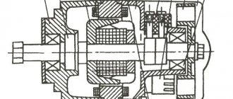
Generator circuit G-424: 1 - cover; 2 — oil seal; 3 - rotor; 4 - stator winding; 5 - terminal block; 6 — back cover; 7 — shield assembly; 8 - rectifier block; 9 - fan; 10 — protective casing; 11 - bearing.
Technical characteristics of G-424
1 – Voltage – 14 volts. 2 – Power – 150 watts. 3 – Full output current – 11 amperes. 4 – Total weight – 3.8 kg. 5 – The direction of rotation of the armature is right. 6 – The polarity of the motorcycle body is negative (minus). 7 – Specific power – 42 W/kg. 8 – Service life – 40,000 km.
The G-424 rotor is driven by a gear mounted on the engine camshaft. The gear ratio between the shafts is 1.33. The cantilever mounting on the crankcase is made with two studs
Adjusting the noise of G-424 gears
Loosen the nuts of the mounting studs and start the engine, turning the generator in one direction or another. We achieve the lowest gear noise. Having established the required gap, tighten the nuts. This is how the gearing of the drive gears is adjusted.
Incorrectly set drive gear engagement leads to overheating, premature gear wear and shaft failure.
Restoration, testing, connection of the G424 generator
This is the kind of generator you want to see on a motorcycle.
And this is what the generator of a Ural or Dnepr motorcycle usually looks like when it has been in operation.
- Let's get started. We disassemble the generator, clean the covers, degrease and prime. With this process everything is clear and does not cause any difficulties.
After the generator is disassembled, you can check the condition of the bearings, oil seal, and brushes. It's better to change it right away. Remove the bearings either with a puller or carefully cut them with a grinder.
Check: Winding on the rotor (armature). Winding on the stator. Checking for breakdown, ground, interturn short circuit and open circuit can be carried out by “continuity” using a multimeter. You can also check the diode bridge with a multimeter. More on this later.
Theory of generator operation and performance testing.
The figure below shows a diagram of the generator assembled (on the left) and on the right, disassembled into three parts.
Diode bridge, Stator winding (non-moving part) connected according to a star circuit and Armature (aka rotor, what rotates), brushes are just feed contacts.
Troubleshooting or testing should be divided into three parts: checking the stator winding, checking the armature winding, checking the bridge.
But first we should remind you how it all works.
Operating principle of three-phase alternator:
1. Excitation voltage is applied to the rotor winding using graphite brushes through contact rings.
2. Rotating inside the stator winding, the rotor winding through which current flows induces an EMF in the stator winding. Faraday's law. There are 3 stator windings and they are out of phase by 120 degrees.
3. The alternating voltage is removed from the stator windings and converted to constant voltage by a diode bridge. In the diagram and graph below it is clear how alternating current is rectified into direct current by diodes.
In a three-phase alternating current generator, there is no permanent magnet; instead, there is an electromagnet in the form of one winding on the armature, which, when voltage is applied to it, “excites” generation.
This is what the assembled generator looks like with a circuit diagram superimposed on it.
Below is a diagram of connecting the generator to the on-board network with a relay regulator of a new three-pin model and an old one.
The difference in the above diagrams is in the relay regulator. In the circuit with the VAZ regulator, it is not necessary to connect the generator control terminal. The regulator itself has status diagnostic indicators.
The generator in the on-board network of a motorcycle is controlled in the same way as in a car.
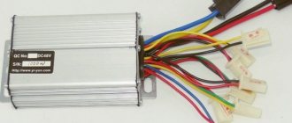
A modern relay regulator is built on semiconductor elements and there is no relay in it as such; instead, an electronic key is organized, which is either open or closed. Also, the regulator relay contains a measuring element that is capable of measuring the generator output voltage and checking it with its reference voltage. At the moment when Uout. — the voltage at the generator output will be greater than Uop. - voltage support, RR will remove power from the excitation winding and generation will stop.
The engine is started and the rotor rotates in the stator winding, voltage is supplied to the excitation winding through the PP and the generator is excited. As long as the voltage supplied by the generator and the PP regulator is not high, it monitors that power is supplied to the excitation winding.
By increasing the engine speed, the voltage on the generator will increase, since the dependence of the voltage on the generator speed is proportional. The PP will supply power to the field winding as long as the generator voltage meets the limit set in the PP control circuit. This limit usually ranges from 0 to 14 Volts. As soon as the voltage on the generator goes beyond the permissible limits, the PP will turn off the excitation winding.
At idle speed, there is usually no charging in Ural motorcycles. This is caused by the fact that despite the fact that excitation power is supplied and the generator rotates, the voltage at the generator output
It is necessary to remove the brushes and the plastic holder to access the slip rings. Set the multimeter to the “continuity” mode and connect the probes to the slip rings.
The device should show a short circuit. This is a regular two-contact coil. Next, you can check whether there are short circuits between the rotor and its core on which it is wound and, accordingly, short circuits to the housing. One probe for the contact ring, the second for the body or the armature itself. There should be no short circuits. The device should show infinite resistance.
Generator G-414 of the Ural motorcycle.
The first production of motorcycles used six-volt electrical equipment. Accordingly, the generator generated direct current at the required voltage. It is installed in a special hole in the engine crankcase and secured with a tightening tape. Adjusting the gear engagement as on the G-11A is described above.
Generator circuit G-414:
1 – anchor; 2 – winding; 3 – bandage; 4 – collector; 5 – cover; 6 – rear bearing; 7 – cover; 8 – output; 9 – shields; 10 – coil; 11 – body; 12 – front cover; 13 – protective washer; 14 – front bearing; 15 – oil seal; 16 – key; 17 – castle nut.
Motorcycle relay regulator
Motorcycle equipment is equipped with a large number of mechanisms that must work efficiently and smoothly every day during the motorcycle season. The operation of all systems and components of motorcycle equipment must be regulated so that sooner or later the motorcycle does not fail and does not turn into a pile of metal. For this, there is a certain mechanism called a relay regulator. They are used to ensure that the voltage for the movement of the motorcycle is supplied to a certain level.
How does a relay regulator work for a bike?
Normally, the voltage supplied to the on-board circuit of any motorcycle device should not exceed twelve volts. However, the generator is capable of producing a higher voltage level. Typically it ranges from eight to forty-five volts. If such voltage is regularly applied, all motorcycle electronics may fail. The motorcycle will turn into a pile of metal. It is to protect against power outages that a motorcycle relay regulator is installed on motorcycle equipment.
Relay regulators are installed on all imported motorcycle vehicles. The role of the regulator relay is colossal. Thanks to it, you can avoid expensive motorcycle repairs. In addition, all systems are guaranteed to work like a well-oiled mechanism and will not fail for a long time due to failures in the voltage supply to the on-board networks of the motorcycle.
Motorcycle Voltage Regulator Relay Diagram
What to do if the relay regulator is broken
Sometimes a situation occurs when the relay regulator becomes faulty. In this case, there is no need to panic. It is very important to take certain measures to prevent all motorcycle systems from failing.
First, you urgently need to disconnect this device from the generator and from the battery so that they do not fail. The voltage will be supplied alternately.
The main thing is to pay attention to ensure that the generator does not fail. In this case, the voltage will be supplied from the battery, where there is a possibility that it will begin to boil away and increase in size. The result will be an explosive situation.
The motorcycle regulator relay diagram shows its structure. Thanks to this, you can figure out how to repair it and connect it.
How to check the relay?
In general it was like this. I was getting ready to start my trike, which had been sitting outside all winter. After charging the battery, cleaning the contacts and replacing some substance in the gas tank with gasoline, I finally revived it. And since the ignition key was lost and the lock itself was completely broken, I could not turn off the ignition. This means the engine is working, but I don’t have the brains to take off the candle holder to turn it off (there is no engine stop). So, instead of disconnecting the positive wire going to the coil, I short it to ground. The engine died down and, in general, all signs of life along with it. I looked at the fuses, one was burned out, I replaced it, everything was still dead. To clarify, this means that the charging control lamp does not light up. Then I took a piece of wire and connected the plus directly to the coil. The lamp does not light, mind you. So I start it and the light comes on. I have a separate breaker for the generator, so I turn on the generator, the lamp starts blinking. I turn off the engine, the lamp goes out. So the main question! Which of the two relays burned out? The wiring works according to the scheme described in https://custom26.ucoz.ru/forum/5-127-1
nait9, the control light is in your hands. and check for the presence of a plus where it should be. With a multimeter in low-resistance circuits, there is little that can be adequately checked other than the integrity of the wires.
IMHO the relay-regulator burned out. When my control lamp relay burned out after a short circuit, the control lamp was constantly shining, despite the fact that the RR was regularly charging. If you buy a new RR, look for one with diagnostic LEDs. RRs are the size of a matchbox.
All is good! The topic can be closed. I decided to do as Vetal41rus advised. I checked the power supply to the lock using a test lamp. Not finding it there, I took a piece of wire and connected it directly from the plus of the generator to the lock. The lamp works, the engine starts, the gene snorts. Looks like the wire has burnt out. Remove the tank. I just filmed it again. Eh.
In what cases can you ride a motorcycle without a regulator relay?
It is not recommended to drive without a regulator relay. However, there are situations when it fails. It takes a lot of time to restore it. Therefore, many motorcyclists do not wait for repairs and risk going on trips without this device.
Experts are skeptical about such risky trips and recommend driving without a regulator relay if:
- the battery has an absolutely full charge level,
- The battery is in perfect working order,
- The relay regulator must be in the off state.
The battery on the Ural motorcycle does not charge
After the engine was restored to working order, the motorcycle started, but the battery did not charge. In connection with this, the generator and relay regulator were completely checked. In the end, the reason was in the relay regulator. Moreover, I changed the relay-regulator to a new one. Or rather new in the sense that it had not been used before, but its year of manufacture was old, which was the reason it did not work. And now in more detail and in order about the process of checking the generator and relay regulator.