Why is it worth ordering spare parts from us?
If you have already selected a suitable option, simply fill out the online form on the website, and if you can’t make a choice, call our consultants. Depending on the nature of the breakdown, we will help you decide on the purchase of rare spare parts for the Izh, Jupiter and Planet motorcycles. All specified components come with a quality guarantee. You will return your vehicle to working order with minimal investment of time and money.
The advantages of working with us are the extensive experience of our specialists in selecting components for Soviet motorcycles, the availability of even rare samples and the supply of only original and high-quality spare parts from reliable manufacturers.
Jig for machining the connecting rod upper head bushing.
During a major overhaul of an engine in which plain bearings (bronze bushings) are used in the upper head of the connecting rod, an increased gap is often found in the interface between this bushing and the pin; the gap occurs after a certain mileage. This causes an unpleasant knocking sound when the engine is running, which only intensifies with each kilometer passed. Naturally, when repairing an engine, you need to get rid of such a nuisance. But everything is not as simple as it seems, especially with domestic engines, and such a small part can cause big problems with the piston group. How to avoid these problems, and how to carry out repairs correctly and with what help, read on.
The first option: if the gap is not very large, then the bushing is unrolled using a reamer of a certain diameter (the corresponding diameter, depending on the diameter of the repair pin) to remove the oval caused by the uneven development of the hole in the bushing, and then a pin of increased diameter (repair size) is installed, and As a result, you get a hole in the bushing with an ideal round cross-section and a diameter slightly larger than the diameter of the repair pin. How much larger this diameter (the gap between the pin and the bushing) can be found out exactly in the manual of a specific (your) engine.
The second , more complex option: if the diameter of the worn out oval in the bushing is much larger than the thickest repair pin (with the largest diameter that you find), that is, the required working gap tolerance, after processing the oval hole in the bushing, you will not achieve the bushing The upper head of the connecting rod must be pressed out of the head and a new one must be pressed in. The new bushing again needs to be unrolled using a reamer of a certain diameter, which depends on the diameter of the repair pin.
What a quality bushing should be like.
That is, in all cases (in two versions) you need to use a scan, but the most crucial moment in this seemingly simple matter is not taken into account by many, but in vain. Which moment? Yes, just the absolute parallelism of the hole in the upper head of the connecting rod and the hole in the lower head of the connecting rod, which many do not pay attention to during repairs. That is, they simply turned the hole with a reamer, but at what angle the tool passed, and at what angle the turned hole is obtained, relative to the hole in the lower head of the connecting rod, is not important to many, but in vain.
If these two holes are not parallel, then the piston of your engine after assembly will work skewed, and the piston skirt will wear out unevenly (not over the entire surface, but only on one side) and very quickly, since the friction area is not full (small) . This is what causes the knocking of the piston on the wall of the cylinder liner, and this knocking occurs quite quickly after improper repair. Many drivers blame this problem and blame the supposedly low quality of spare parts. But in fact, the repair was simply not done well, that is, the parallelism of the holes in both connecting rod heads (lower and upper) was not maintained.
Conductor and its manufacture.
To ensure that the hole turns out correctly when unrolling with a reamer, you should make a simple jig that will help you correctly unroll the hole in the bronze bushing. To make it, you will need a piece of thick-walled tube, with an internal diameter slightly smaller than the hole in the bronze bushing, and you will also need a pair of sheet metal plates, approximately 8 - 10 mm thick. It is advisable to cut the pipe on a pendulum saw, which will allow you to make a cut strictly at 90 degrees, or cut it on a lathe. Next, we carefully press the tube to the plate with a clamp (so as not to lead during welding), and weld the tube to the plate (see the picture on the left). Well, in order to be completely sure that the plane that will be pressed to the connecting rod head and the tube (hole in the tube) are absolutely perpendicular (at 90 degrees to each other), you should grind the outer plane of the plate in one installation in the lathe chuck , and bore the hole in the tube, and achieve a slightly larger diameter (a couple hundred square meters) of the hole in the tube than the diameter of the reamer you will use.
All diameters in this picture correspond to a 14mm bronze bushing diameter.
All that remains is to cut out one more plate, which will be pressed with bolts on the other side of the upper head of the connecting rod. You should make a hole in this plate that is a millimeter larger than the diameter of the reamer you are using. Well, you should also drill coaxial holes for the tightening bolts (see picture on the left). During operation, both plates need to be tightened with bolts, but not tightly, but so that the jig can move along the plane of the upper head of the connecting rod by hand force, or by pressing firmly with your finger. Now all that remains is to install and tighten the jig with bolts opposite the hole in the bronze bushing, and you can begin to unravel this hole using a reamer. The processing accuracy will be excellent.
But everything is not as simple as it seems.
The method I described above for processing the hole in the upper head of the connecting rod will be very useful for those engines in which the connecting rod, as it should be in principle from a normal imported manufacturer, is perfectly flat, and the holes of both connecting rod heads are strictly parallel (what kind of connecting rods and their bushings are there, how to properly finalize and much more can be found here). At our factories, for example, connecting rods for IZH motorcycle engines are made differently, and the repair method using the jig I described above may not be suitable. I'll explain why.
When the connecting rod of an Izhevsk engine is made at a factory, the steel from which it is made does not undergo heat treatment to strengthen the connecting rod until both holes are made in it - in the upper head and in the lower head. The thermal tool is not yet used, since it is easier to make holes in raw metal, probably at the factory they save on high-quality carbide tools. They make the holes in both connecting rod heads correctly, that is, up to this point they are strictly parallel. But after the holes are made, the connecting rods are sent to a thermal shop for hardening and hardening of the part (the part is heated and then sharply cooled). This is where the fun begins. After heat treatment, the connecting rod bends due to heating and sudden cooling, and the holes in its heads are no longer parallel from this moment on.
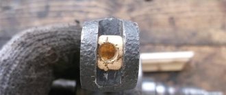
How does the Izhmash plant get out of this situation? The parallelism of the upper and lower heads of the connecting rod is restored at the factory using the thickness of the bronze bushing, that is, by unfolding the bronze bushing, but the reamer is already installed using a factory device that allows you to unfold the hole in the upper head strictly parallel to the lower one. The bushing is obtained with different wall thicknesses in different areas around the perimeter of the part (see the figure on the left).
The funny thing is that many motorcyclists who repair domestic engines do not know this nuance, and having opened the hole even with the help of a jig, they are surprised that after repair their engine quickly begins to knock with double force. What everyone says in this case is that, naturally, supposedly low-quality parts are to blame. In fact, everything is quite simple: the plant saves on technology and high-quality processing tools, many do not know this and carry out repairs incorrectly, but in the end there will always be someone to blame - this is either the repairman to whom you entrusted your engine, but he does not know this joke, or the supplier of supposedly low-quality spare parts is to blame. Agree - it sounds implausible: you are buying a new domestic motorcycle, and the connecting rod or connecting rods of your new engine are crooked (misaligned). Such a joke can only happen in our native fatherland, in our factories, that is, on our domestic technology, there is nothing to be surprised about.
New motorcycles seem to ride normally, since both connecting rod bushings are parallel and seem to be without knocking, until the bushing wears out from natural wear and tear. After this, the matter comes to repair and this is where the problems that I described above begin. So how can you make a high-quality repair of the upper bushing on a factory crooked connecting rod? (the very expression of a factory crooked connecting rod, to be honest, infuriates me, but this is the harsh reality of the domestic motorcycle industry). To properly rotate a new bronze bushing into a crooked connecting rod, there are three options, two of which can be used...
The first option is to ensure that both holes in the upper head (without the bronze bushing) and the lower head of the connecting rod become parallel. This is achieved by straightening the connecting rod on the plate, and checking the parallelism of both holes using the tools shown in the lower pictures. And it is better to straighten the connecting rod not using impact equipment (copper hammer), but leveling the connecting rod using a hydraulic press (we press on the connecting rod by inserting an aluminum blank between it and the press). After straightening the connecting rod and restoring the parallelism of the holes of both connecting rod heads, it will be possible to use the reaming jig described above in this article.
The second option is not to press out the factory worn bronze bushing from the upper head of the connecting rod, but simply restore its hole using the MS-2000 hard coating, which you can read about in this article. The service life of such a restored bushing will be longer than that of a new one, and so will the piston pin. The only nuance that should be taken into account is that when processing the hard surface and adjusting the hole for the piston pin, you should again ensure that the piston pin and the crankshaft pin are parallel. This is not so simple, because for this you will need to constantly check the parallelism of both holes and the fingers located in them, using the devices shown in the lower figures.
Well, the third, most time-consuming option is to make a device that will allow you to secure the reamer strictly parallel to the hole in the lower head of the connecting rod. To do this, you need to grind a cylindrical mandrel roller (mandrel 5 - see the figure below), which will fit tightly (with minimal clearance) into the hole in the lower head of the connecting rod; another perfectly straight connecting rod is tightly placed on the other end of this roller, and the hole in the upper head of this The connecting rod will be used as a guide hole for reaming (you will now have two points of support for reaming - the machined support and the supporting support - the bushing). Moreover, I advise you to tightly insert a tube or bushing approximately 50 - 70 mm long into the hole in the upper head of the auxiliary connecting rod. This will increase the contact area of the reamer, which will be inside this tube (the gap is again a couple of hundred square meters) and will allow more accurate use of the device.
Which option to use, choose for yourself, but I think it’s still worth using one, because it’s better to do the correct repair once and forget about it for 50 thousand, than to re-assemble the engine every couple of thousand.
Explanation for the bottom figure (b), which is on the right. This figure (Figure b, bottom right) shows a device for checking the straightness of the connecting rods. To do this, the connecting rod 2 is installed with the upper head 3 on the control pin 4, and with the lower head on the pin 1 of the control plate 6. Then the control prism 5 is installed on the pin of the upper head and brought it so that the pins of the prism touch the surface of the plate 6. And if the connecting rod is straight, then all three pins of prism 5 will touch plate 6. If some pin or two pins of prism 5 do not touch plate 6, then the connecting rod is curved, and how much of the curve can be determined using probe 7 inserted into the gap between the pin and plate 6. For a normal connecting rod that can be allowed to work, the clearance should not exceed 0.05 mm.
If the connecting rod has a double bend, which cannot be detected using the above method, then it can be checked using the method shown in figure (c) (also at the bottom right). It is necessary to clamp the connecting rod on pin 2 if the pin has a smaller diameter than the hole in the lower head (as in the figure). If the connecting rod fits tightly onto the pin you have turned, then there is no need to clamp it. Then, on the control plate, extend limiter 3 until it stops at the end of the lower head of the connecting rod, and clamp the head. Then, using a micrometric depth gauge 4 (the depth gauge can be viewed here) the distance from the end of the upper head to the plane of the plate, then we remove the connecting rod from the pin and turn it 180 degrees, and again put it on the finger, resting against the limiter - we make a second measurement with the depth gauge. The difference in the numbers in the measurements will show the curvature of the connecting rod.
In conclusion, I would like to advise those people who do not want to bother with repairs, but simply want to buy a new crankshaft (crank) for their engine and simply replace the knocking crankshaft with it. Nowadays there are a lot of left-wing products on sale, especially for domestic equipment. And in order not to buy a defective crankshaft , I highly recommend reading this article. It will help you distinguish a left-handed product from a quality product when purchasing. Good luck everyone!
Checking the parallelism of both connecting rod heads, and also this check allows you to check for bending (a) and torsion (b). 1 - auxiliary connecting rod; 2 - cylinder tightly inserted into the upper head; 3 - pointed rod; 4 — connecting rod being tested; 5 - cylindrical mandrel; 6 — mandrels in the form of mushrooms.
Checking the parallelism of both heads of the connecting rod and its straightness Fig. b. 1 — cylinder mandrel; 2 — connecting rod; 3 - upper head; 3 - limiter; 4 — piston pin; 5—test prism; 6 - control plate; 7 - dipstick; 8 -screw;
If this article is useful to you, please share it on social media. networks by clicking the buttons below. Thank you.
RќСЂР°РІРёС‚СЃСЏ
