Installation of the cylinder-piston group
It is not advisable to remove the gearbox cover until the sealant has dried; there is no need to rush in this matter.
It’s better not to rush things and install the cylinder while the sealant dries. Add some motor oil:
To improve lubrication, it is advisable to drill holes in the piston bosses. But you don’t have to drill - it depends on your desire.
Install the piston pin retaining ring into the boss. Before installation, it is advisable to bend the locking ring a little and be sure to check how it fits after installation:
We heat the piston with a hairdryer and, using a mandrel, drive the finger into the piston so that it comes out no more than 5-6mm.
We look for an arrow-shaped mark on the bottom of the piston.
We orient the piston with the arrow towards the exhaust port of the cylinder (“towards the exhaust”), put the piston on the connecting rod, hammer in the piston pin and install the second retaining ring.
We insert the rings into the cylinder and measure the gap between the locks with a feeler gauge:
To improve the wearability of the rings and reduce noise from engine operation, it is advisable to chamfer the edges of the rings. If hunting gets too much trouble: place the ring on a flat surface and use a file to slightly round the edges.
We put the rings on the piston, fill the piston with the rings with oil, install a gasket under the cylinder (preferably with sealant), tighten the rings with a clamp. We cut the clamp out of tin and from the same tin we bend the bracket with which we will fix it.
After the rings go into the cylinder, unfasten the clamp, lower the cylinder and screw it to the crankcase.
We turn the crankshaft several times and if the piston moves in the cylinder easily and without grinding, lower it down a little, pour a little engine oil into the cylinder, install a new gasket on the cylinder and screw the head on.
We install the additional crankshaft support bearing in its place, place the required number of adjusting washers on top and secure it with a retaining ring. The adjusting washers must ensure axial play of the crankshaft within 0.1 mm.
Before installation, sealed bearings must be opened! The usual 304 goes here.
On the other side of the crankshaft we install a flange with a main oil seal.
Pay attention to the oil channel through which oil flows to the right main bearing of the crankshaft. According to the good old collective farm tradition, this channel is sealed with sealant and the lubrication of the bearing stops
To avoid this trouble, place the flange dry without sealant and everything will be fine.
After the sealant has dried, you can begin adjusting and assembling the gearbox and replacing the clutch basket.
Numbers of bearings and oil seals for the Izh-Planet motorcycle engine 2, 3, 4 and fifth model.
Motorcycle IZH-Jupiter technical characteristics
Home > IZ Reviews
Motorcycle IZH-Jupiter technical characteristics general data
Motorcycle type - single Base, mm - 1360 Ground clearance, mm -135 Dimensions, mm: Length - 2115 Width - 780 Height - 1025 Saddle height - 780 Motorcycle dry weight, kg -160 Maximum speed, km/h - 110 Fuel tank capacity , l — 15 Fuel consumption rate on the highway, l/100 km — 4 Fuel range, km — 375 Filling oil capacity, l: gearbox housing — 1 each front fork leg — 0.15 rear suspension elements (two) — 0 .12 air purifiers - 0.2
Motorcycle IZH-Jupiter technical characteristics engine
Engine type - two-stroke with two-channel return purge Number and arrangement of cylinders - two, vertical in-line Cylinder diameter, mm - 61.75 Piston stroke, mm - 58 Displacement, cm cubed - 347 Compression ratio - 6.7 - 7.0 Maximum power, l. With. — 18 Number of revolutions at maximum power, rpm — 4700-5100 Tax power, n. pp. - 1.33 Cylinder head: material - aluminum alloy combustion chamber shape - hemispherical Gasket material - rayasbestos Piston: material - aluminum alloy shape - convex Number of piston rings - 3 Piston pin (type) - floating Piston pin diameter, mm - 14 Protection against axial displacement - with stoppers. Valve timing, in degrees of crankshaft rotation: beginning of intake to c. m.t. - 75° end of intake after c. m.t. - 75° start of release to c. m.t. - 80° end of release after n. m.t. - 80° start of blowing after n. m.t. - 58° end of blowing after n. m.t. - 58° Engine lubrication - oil with gasoline Carburetor - K-28Zh Air cleaner - contact-oil Fuel filter - mesh in the sump
Motorcycle IZH-Jupiter technical characteristics power transmission
Clutch - multi-plate in an oil bath Gearbox: type - four-speed control - foot gear ratios: in first gear -3.17 in second gear - 1.71 in third gear - 1.26 in fourth gear - 1 Total gear ratio (from the engine to the rear wheel): in first gear - 18.98 in second gear - 10.24 in third gear - 7.54 in fourth gear - 5.89 Forward gear: type - roller chain gear ratio - 2.57 Rear gear: type — roller chain gear ratio — 2.63 Chassis Frame — tubular, non-separable welded Front fork — telescopic with hydraulic shock absorbers Rear suspension — lever spring with hydraulic shock absorbers Tires: type — straight-bezel size in inches — 3.25-19 Brakes — shoe brake drive — mechanical separate
Motorcycle IZH-Jupiter technical characteristics ignition, electrical equipment
Ignition system - battery Battery battery: brand - 3-MT-7 capacity, a-h - 7 voltage, V - 6 Generator: brand - G36M2 voltage, V - 6 power, W - 45 Drive - the generator is mounted on the right axle of the crankshaft engine Regulator relay - two-stage Ground connection terminal - minus Signal - S-37 Headlight - FG-38
Similar articles:
Installation of bearings and seals
We install a retaining ring in the left half of the crankcase.
Depending on the model of the main oil seal, we install a spacer sleeve in the mounting hole of the main bearing, or, if the oil seal was initially wide (there are some), we heat the crankcase and, on the inside of the crankcase, place the oil seal until it stops against the retaining ring.
My engine had a regular narrow oil seal, so I put in a bushing.
Using a mandrel, install the main oil seal into the preheated crankcase.
Quickly, before the crankcase cools down, place the oil guide washer on the oil seal. The oil guide washer has a saucer-shaped profile. We place it on the oil seal so that the concave side faces us, and the curved side faces the clutch basket.
While the crankcase has not cooled down, we press the outer race of the main bearing into it using a mandrel.
If you are going to replace the main bearings with new ones, don’t be lazy: find a sheet of iron 7-8 mm thick, cut a wedge in it for the connecting rod, pass the sheet of iron between the cheeks of the crankshaft and use a mandrel to drive the main bearing onto the axle.
This way you will protect yourself from damage to the crankshaft. The main bearing has a very high interference and fits into the axle with a very large force. It is not uncommon for people to simply knock out the axle (the axle on the planetary crankshaft is pressed into the cheek) inside the crankshaft, but they were never able to put the bearing on.
Source
Gearbox Izh Planet 5
The Izh Planet 5 gearbox is four-speed, three-shaft with constant mesh spur gears and foot-operated gear shifting. Switching is carried out using a copy shaft, which is located inside the box; the shift fork pins fit into its grooves. The copy shaft rotates from the shift selector, which in turn is connected to the foot lever. The secondary shaft is hollow and fits onto the end of the primary shaft. The main gear sprocket is located on the secondary shaft. The gearbox is located in the same crankcase with the motorcycle engine, together forming a single power unit. The gearbox is lubricated by oil poured into the engine crankcase. The IZH Planet 5 gearbox can be disassembled without removing the engine, however, for complete disassembly and greater convenience, you can remove the engine from the motorcycle frame. Today we will look at disassembling the Izh Planet 5 gearbox step by step.
Engine IZH Planet!! DETAILED GEARBOX ASSEMBLY: assembly and adjustment of the gearbox. (Ch-2)
Published May 23, 2018
please tell me I have this problem, when you engage first gear it starts to skip, sometimes it catches, sometimes it doesn’t, help me, tell me))
And where does such a specialist live?
Very useful video, thank you)
I actually have a brass washer on the shank of the input shaft, I bought it with this one and left it there
I assembled the box with all the details, eliminated the backlash, etc., by rotating the wheel, the gears were all there, but as soon as I started it, the gears all disappeared. I was barely coasting. what is the reason?? maybe the cart is slipping?
Quite an introductory video, could you tell me why there are no 3rd and 4th gears? When the second switch is turned on, the switch foot does not go higher and does not switch.
He explained everything perfectly! And about the coins, that’s the most important thing.
I also use a grinder to work on worn-out holds, otherwise the speeds go out of whack.
Dmitry, I have an S 62 motor. Can you restore the city of Ternopil?
Tell me, I have Izh Planet 4 when driving in first gear and second gear, why does the box jerk?
Tell me, with Izh plan 5, can I install a gearbox?
Good video, but I have Jupiter 4, and here my friends fitted two planets with spare parts, each shorter, but the engine on each is assembled. After watching your video, I decided to take them on. Everything is simple and easy))) in your video. There is, as they say, what a waste of time. Thank you for your work. Definitely a like.
Tell me why the gearbox rattles on the Izh PC 4 speed, is it all there? especially 2nd gear and 3rd
Please tell me what the problem is, I put everything under the worm shaft like you have, under the plate where the clutch drum is located everything is flush, when switching from 1 to 2 sometimes it doesn’t turn on 2, you have to turn on from 1 to 3, and then the second, and 3 and 4 Everything is fine
Instructions for assembling the gearbox for IZH Jupiter 5 | Topic author: Deidre
Hello, please post instructions on how to properly assemble the gearbox on an IZH Jupiter 5. I bought a Yupak secondhand, it was completely disassembled! I’m looking at the box of all sorts of washers and bolts for gears and I don’t know what to put where, tell a newbie how what and where should be in the gearbox, it would be nice to have a “video” or at least “draw a picture” =) please give me an idea))
Alexander (Kumaree) there are detailed instructions in the Jupiter book.
I changed everything based on it
Maxim (Kalen) Can you take a photo of this book for me where you read the assembly instructions?
Alexander (Kumaree) there is this. there you can search https://www.motoizh.ru/. but I can’t take a picture. the camera is covered
Alexander (Kumaree) https://www.moto4you.ru/content/view/68/29 Here’s something else I found. There are instructions text + pictures but this is disassembly. just do the opposite)))
Maxim (Kalen) Thank you very much =)
Alexander (Kumaree) yes you're welcome
Evgeny (Trevon) Alexander,
Vladimir (Nakapati) How should the forks be positioned on Jupiter 5... Why, when you engage first gear, it sinks and does not turn anything at all, shafts or gears.
Tags: How to properly assemble a gearbox for Izh Jupiter 5
Assembly
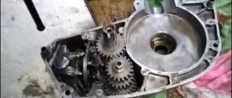
In a carefully washed and prepared for assembly crankcase we place the input shaft, the first gear gear and the follower shaft with pre-selected shims.
We put a fork on the gear-carriage for engaging the second-fourth gear (it is smaller than the gear-carriage for engaging the third-first gear, you can’t go wrong) as shown in the picture. We put the gear on the input shaft and insert the fork pin into the upper groove of the follower shaft.
We put a fork on the gear-carriage for engaging the first-third gear, as shown in the picture, place it on the first gear gear and insert the fork pin into the lower groove of the copy shaft.
We install the fork guides in their places (with grooves towards the clutch basket). By the way, if necessary, the “Planetovskaya” gearbox can be assembled and disassembled without disassembling the clutch basket and without removing the guides. But to do this, during installation you will have to pull the tracing shaft towards you a little, insert the pins of the forks into the grooves and after that, remove the locking bar and push the tracing shaft all the way.
Install the intermediate shaft.
On older engines, the end gear is installed separately. On later ones, it is made integral with the intermediate shaft.
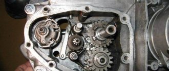
We fill the return spring of the gear shift shaft as shown in the picture.
We check the functionality of the gearshift shaft pawls: compress and unclench them several times
We pay special attention to their working edges: they should be sharp and not licked. And don’t forget to check the spring that compresses the pawls: it must be of the correct shape and ensure the elasticity of the pawls’ movement
We squeeze the pawls and install the gear shift shaft in its place.
We rotate the tracking shaft with the mark on the body towards the gear shift shaft and so as not to miss the mark during installation, we cover the gap between the teeth opposite the mark of the tracking shaft with lithol or paint it. It will be more noticeable this way.
We look for a mark on the sector and when putting the sector on the gear shift shaft, we combine the mark on the sector with the mark on the tracking shaft body: the tooth opposite the sector marks should strictly fit between the teeth opposite the mark of the tracking shaft.
To ensure that our marks do not get lost during installation, we tie together the sector and the copy shaft with ordinary sewing thread.
We put standard thrust washers on the input and follower shafts and insert the guide bushings of the gearbox cover into place.
We degrease the surfaces, apply sealant, lay the gasket, install the cover and tighten the mounting bolts with the maximum possible force. We adjust special washers under the bolts marked with yellow arrows.
After tightening the gearbox cover, we check the axial play of the primary and secondary shafts. Normal: 0.2-0.4mm.
If the play is greater than normal, remove the plate, seat the bearing and adjust the required number of shims under it.
Motorcycle IZH Jupiter disassembly and assembly of gearbox
Disassembly and assembly of the gearbox and shift mechanism of the IZH-U motorcycle are carried out as follows.
Disassembly. Remove the engine from the frame and disconnect the carburetor pipe. Remove the shift pedals and kick starter, drain the oil from the gearbox crankcase by unscrewing the plug. Unscrew the mounting screws and carefully remove the left crankcase cover without damaging the paper gasket, and also remove the right cover. Disassemble and remove the clutch mechanism. Remove the hatch cover located at the bottom of the crankcase and loosen the flywheel pinch bolt. Remove the lower pipe of the rubber boot and, by unscrewing the seven screws and the flywheel tightening bolt, separate the crankcase into two halves. All gearbox parts, except the output shaft, can be removed from the crankcase. To disassemble the shift mechanism, you need to remove the clutch release cam and remove the key. When disassembling, it is necessary to monitor the order in which the parts were assembled. Pay special attention to the adjusting washers. Assembly. The gearbox and shift mechanism are assembled in the right half of the crankcase. Install the shift mechanism shaft along with its parts and key. Place the clutch release cam and secure it. Install the intermediate shaft into the ball bearing without the first gear and the input shaft, putting a 2 mm thick ring on it. Install the worm shaft and shift forks, connecting them to the carriage gears of the primary and secondary shafts, and put a 1.4 mm thick adjusting washer on the right end. The worm shaft is installed so that the existing core marks on the sector teeth and the worm shaft coincide. This is important for proper gear engagement.
Place a key on the crankshaft axle shaft of the right half of the crankcase and put on the flywheel. Clean the crankcase connector surfaces from varnish and re-coat them with bakelite varnish. Insert the key into the left crankshaft axle shaft. Place an adjusting washer 0.2-0.3 mm thick on the left end of the worm shaft. Inserting the first gear gear into the left half of the crankcase and supporting it with the fingers of your left hand, through the hole in the crankcase wall, begin connecting the left half of the crankcase with the right, for which you put the left half of the crankcase on the gear shift shaft and, turning the flywheel, align the crankshaft key with the flywheel keyway and connect the crankcase halves. At the moment of connecting the crankcase, after the first gear gear is put on the intermediate shaft, use a screwdriver to remove the gear shift lock through the hole in the crankcase, which will allow the worm shaft to fit into place. Once the crankcase is connected, secure the mounting screws. Set equal gaps between the flywheel and the crankcase walls, and then tighten the flywheel pinch bolt until it stops.
Source
Repair
Once the unit has been gutted, you can begin to determine the parts that need to be replaced. As a rule, you have to buy a set of shims, a set of gaskets and sealant. This is the case if there are no more serious damage. Once you have decided on the elements to be replaced, you will need to adjust the worm shaft axis, and after final assembly, the clearance along the axis of the primary, intermediate and secondary shafts.
Adjusting washers are placed on the far ledge of the copy roller; they should be lubricated with a special compound. A support washer is mounted on the near edge, and the shaft is put in place. It should be turned so that the neutral sensor with its protrusion fits into the deepest groove. Then, using a ruler (without the gearbox cover yet) on the plane of the crankcase, measure the gap between the washer and the dipstick. It should be no more than 0.2 mm. Depending on the indicator, regulators are added or removed. If it is impossible to accurately set the gap, it is better to make it smaller.
Common faults
The simplest method that will help in some cases. Place the motorcycle on its right side, then remove the kick starter and gear shift lever along with the shaft. Then remove the left crankcase cover, and then remove the clutch basket along with the discs. During operation, the gearbox gears wear out, which causes the meshing of the teeth to deteriorate. This leads to slipping and jerking of the transmission until the second gear fails. Sometimes, when replacing a gear, the problem is not always solved, and lies in the wear of the bearings of the input shaft, which moves to the left over time due to vibrations. To fix the problem, you need to remove the stopper of the input shaft bearing, then move this bearing with light blows of a mallet or with a hammer through the “spacer”, so as to move the shaft to the right. To fix it in this position, you should place washers of appropriate diameter under the bearing. Using the number and thickness of washers, ensure that there is no play in the input shaft, then return the bearing stopper to its place, reassemble the clutch basket and other parts in the reverse order.
Important
When performing these operations, follow the mark in the middle part of the sector. It should coincide with a similar mark on the shaft. The last step is to install the crankcase cover. If the work is carried out correctly, it will sit in its place without problems.
It is necessary to ensure that all rods and shafts coincide with their original mounting sockets. They should rotate freely without creaking or jamming. Use moderate force when tightening the screws as the threads in a soft metal crankcase can easily be stripped. All fasteners are tightened evenly to avoid distortion.
Source