How to check the relay regulator yourself
To check the proper operation of the regulator relay, you can remove the device from the car.
The second way would be diagnostics directly on the car. To perform the work you will need a test lamp and a multimeter tester. It is also necessary to prepare a special power supply or charger, wires in advance, and also make sure that the battery is in working condition.
- To check the relay regulator, you need to set the voltmeter mode on the multimeter to be able to measure direct current in the range from 0 to 19 volts.
- Next, connect the multimeter probes to the “poles” of the battery with the engine turned off. Record the data that the voltmeter shows. The voltage should be between 12 and 12.5 volts. After this, the engine starts, and the voltmeter readings are recorded again. Normally, there should be an increase in values after starting the internal combustion engine to an average of 13-13.5 volts.
- Additionally, it is worth considering that as the engine speed increases, the voltage should also increase. In the middle range this figure is about 14 volts, at high speeds it reaches 14.5.
How to check the charging relay on a scooter yourself?
A relay regulator, or voltage stabilizer, plays an important role in the operation of modern scooters, the main task of which is to stabilize the voltage. At a moped speed of 60 km per hour, the generator is capable of generating voltage up to 35 Volts, and without its stabilization, this can lead to failure of all the electronics of the moped, including the battery. The article will tell you what a voltage regulator is and how to check it on a scooter.
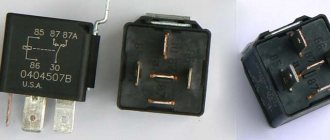
Four-pin voltage regulator relay for scooter
Checking with a multimeter without dismantling
You can check the condition of the relay using a multimeter. In this case, the generator is not dismantled. Before starting diagnostics, it is enough to clean the battery terminals (their oxidation can affect the operation of the car and the readings of the measuring device).
The diagnostic procedure is as follows:
- First you need to start the engine and let it warm up for a few minutes.
- Next, you need to connect the multimeter probes to the battery terminals. The device displays a value of 20V.
- After this, the voltage is measured. It should be within 13.2-14V. Such readings are considered normal for most cars.
- Now you need to increase the engine speed (up to 2-2.5 thousand). The voltage should increase by about 0.2V.
- If it exceeds 3,500 rpm, the multimeter should show 14-14.5V, but no more.
Serious deviations in the readings of the device indicate the presence of breakdowns of the relay regulator.
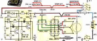
We adjust the contactless ignition system
The contactless system operates through a sensor, switch, primary and secondary ignition windings. When the rotor with magnet closes the sensor, it sends a signal to the commutator, which, in turn, begins to accumulate current from the generator and transmit it to the primary winding. At this moment, high voltage appears in the secondary ignition winding. Its purpose is to ignite the spark. If there are any malfunctions listed above, adjustment is carried out by simply aligning the crankcase and ignition marks; to do this, remove the valve cover. The next steps are:
- We disassemble the crankcase in accordance with the technical description for your car.
- A mark is made on the rotor and crankcase at the dead center position of the engine in a place convenient for viewing.
- By rotating the crankshaft, we achieve a spark, make a mark on the crankcase relative to the mark made on it in the MTD. The difference between these marks on the crankcase is the ignition timing.
- Unclench the stator mounting bolts and set the advance angle corresponding to the technical documentation.
It is important to ensure that two of the three holes in the gear for the chain are at the level of the cylinder, and the remaining one is above the plane in which the cylinder and the mentioned holes are located. The alpha moped has a reliable ignition system, but it can also break; you should not put off this breakdown and ride on a faulty moped
You just need to try setting the ignition. You can set the ignition yourself if you have special tools and minimal skills. If this is not the case, then it is best to contact a specialist.
The Alpha moped has a reliable ignition system, but it can also break; you should not put off this breakdown and ride on a faulty moped. You just need to try setting the ignition. You can set the ignition yourself if you have special tools and minimal skills. If this is not the case, then it is best to contact specialists.
Design of the relay-regulator and external signs of its malfunction
Relay regulator:
- It can be made in the form of one of the modules of the brush assembly, using its structure as a supporting base.
- Or it is a separate element mounted on the body on a bracket.
The use of a separate design is easily visually detected due to the fact that the relay is located in the open circuit of the current flow between the generator and the battery. In any form of its design, the relay is a non-separable monoblock element, the body of which is filled with epoxy or other sealant. This means that a failed component cannot be repaired.
Failure of the relay regulator is accompanied by undercharging or overcharging of the battery. An undercharged battery results in
- the engine begins to start poorly;
- the starter is unable to crank the crankshaft;
- in severe cases, the car turns out to be de-energized and the remaining charge is not even enough to turn on the dashboard indicators.
An unpleasant consequence of overcharging a battery is boiling off of the electrolyte. At the same time, white deposits and streaks appear on its body in the area of the terminals and on the terminals themselves. External signs are not exhaustive and do not clearly indicate a relay malfunction. However, when they appear, a comprehensive check of the circuits and generator circuit is carried out, the list of procedures of which includes monitoring the serviceability of the relay regulator.
This is interesting: 7 reasons for the engine tripping of a cold engine
Common causes of problems with scooter generators
In conclusion, it is worth noting that the failure of a scooter generator is one of the most common problems faced by owners of two-wheeled vehicles. If a malfunction occurs, you may encounter external signs such as a poor battery charge, a weak spark, or some problems with the electrical system. Typically, the reason for the incorrect operation of the generator is:
- Short circuit;
- Wire wear;
- A sharp decrease in the magnetization of the generator rotor, etc.
Before repairing the generator, you must carry out diagnostics and find out the cause of the malfunction, and only then begin repairs or take the device to a workshop.
What is a voltage regulator used for?
The relay regulator stabilizes the voltage of the scooter generator at the required level, not allowing it to increase or decrease the value above or below the norm. This prevents on-board voltage surges from going beyond the established limits (depending on the boards this is 12-14 V) and ruining the work of consumers whose service life is designed to be no more than 13 V.
That is, this part takes on the impulses that arise during the operation of the scooter (turning on the headlights, the starter button) and transfers the resulting thermal shock to itself. In this case, all the heat that could settle on the contacts is generated in it and removed through the device.
Moped manufacturers install charging relays with different parameters on scooters and select them individually for each. Depending on the regulator circuit, the connectors also differ. Chinese models usually have 5 terminals (male), while Japanese models have 4.
Thursday, September 28, 2021
Carburetor diagram for 139qmb
| Carburetor outlet channels. “Fuel injection channels” - used at the moment of opening the throttle valve, that is, they are used as transition channels at the moments of closing/opening the valve |
Throttle valve limit screw.
Information from a post on one automobile forum regarding the same screw, but on a car carburetor:
But what about this (quote from the Daewoo Nexia primer): . The initial position of the throttle valve when the accelerator pedal is released is adjusted and fixed with a limit screw at the factory. This damper position provides sufficient air flow in the intake manifold to install the IAC shut-off element in the required discrete position during automatic frequency control. It should be noted that in relation to this engine, the initial position of the throttle valve cannot be considered as the position corresponding to the minimum idle speed. The head of the idle speed limit screw is closed with a cap. Warning It is prohibited to remove the protective cap of the limit screw and make adjustments. Incorrect adjustment may result in damage to the IAC or throttle body. .
| The throttle stop screw is not intended for adjusting idle speed! This screw limits the movement of the damper to prevent it from wearing out/jamming. |
| According to the manual, the standard setting for the idle speed adjustment screw is two turns +\- 1\4 |
Check all O-rings for damage. Replace if necessary. A poor seal at the seat of the enrichment valve has a very negative effect on the stable operation of the carburetor and, accordingly, the engine.
When cleaning the carburetor, remove the vacuum diaphragm before using purge air or cleaning solvents. This will prevent damage to the diaphragm.
Excellent video with an animated demonstration of the carburetor:
Possible malfunctions of the CVK carburetor
1.The engine is difficult to start
— No spark - Poor compression
2. There is no fuel in the carburetor
-Closed fuel line -Closed fuel filter -Blocked vacuum line -Damaged/broken vacuum line -Clogged inlet needle -Float level set too high
Float level: with this position of the float, the needle should just close the fuel line.
| The carburetor is in an inverted state, the float presses on the needle with its own weight. The measurement was taken from the center of the protruding seam of the float and to the horizontal plane on the carburetor body, photo below. |
| reference points for measuring the position of the float |
It is also worth paying attention to the needle itself and the float. It has a spring-loaded stop, or rather a rod, through which the float tongue presses on the needle
So, when adjusting the carburetor or repairing it, you need to pay attention to this emphasis. It happens that when the equipment is idle for a long time, this spring-loaded rod gets stuck and it does not play on the spring. If this happens, you need to develop it using liquid keys or diesel fuel. If the rod turns sour tightly, it is better to replace the needle.
| Compressed needle stop |
In a strictly horizontal position, the protruding line on the float and the line on the exhaust tract of the carburetor, the spring-loaded stop of the float needle should take the middle position.
3. Too much fuel for the engine
-Dirty air filter -Air leak in the intake manifold -Faulty enrichment valve ( jammed or bad seal at its seat)
) -The air channel in the carburetor is blocked
4. Air/fuel mixture too rich or too pale
-The enrichment valve is faulty ( jammed or bad seal at its seating location)
) -Idle screw too tight -Float needle stuck or dirty -Float height too high or too low -Carburetor air passage blocked -Air filter dirty -Carburetor or manifold leaking air
5. Engine does not accelerate
-Bad spark -Air mixture screw too tight -Accelerator pump faulty
6. Almost does not respond to the throttle
-Weak spark/poor ignition -Blocked fuel line -Blocked fuel filter -Bad fuel -Water in fuel -Air leak in carburetor or manifold -Faulty enrichment valve -Fuel movement in carburetor is difficult -Vacuum choke stuck -Damaged vacuum diaphragm -Dirt in carburetor
How to check the generator relay with a multimeter without removing it from the car?
Signs of regulator failure are clearly visible. Especially if the temperature outside is sub-zero. The battery will always be either undercharged or overcharged. In the first case, a weak battery charge can be easily determined by how the starter turns the engine. He will barely twist it, and to no avail. Sometimes when you turn the key, nothing happens at all, and the lights on the panel go out.
Recharging the battery is practically no different. The same thing will happen, plus the electrolyte from the battery cans will boil away. Overcharge can be determined by the decrease in electrolyte in the banks. As a result of evaporation, a white coating may also form on top of the battery. Parts of the body under the battery may also have a white coating
Usually, with such symptoms, drivers think that the battery is damaged, but in fact there is nothing wrong with it, but the problem is in the relay-regulator, and that is what you need to pay attention to first. But for this you must know how to test a relay with a multimeter
This is not difficult to do. To do this, take our multimeter and set it to voltmeter mode. With its help, we can measure the voltage when the motor is turned on. Note that when the engine is turned off, the normal voltage should be in the range of 12.4-12.7 V. If, for example, the voltage is 12 V, then the battery needs to be charged and the reasons for the undercharging should be looked for.
How to check the generator on an alpha moped with a multimeter
Checking a scooter's generator is a fairly important and sometimes necessary procedure for every owner of this two-wheeled vehicle. Unfortunately, it can be difficult to establish its functionality, especially if you do not have deep knowledge in the field of electrical engineering, as well as the necessary tool - a multimeter tester . If you have such a tool, then before checking the generator you will need to familiarize yourself with the concepts of alternating and direct current, voltage, electrical impulse and tester indicators.
To check the generator on a scooter, you need to remove the plastic around the engine, and then measure the indicators - first of all, the voltage . You need to remove the casing as carefully as possible, otherwise you will damage the fastening system.
Find the place where the bundle of wires comes out of the engine and move along it to the connector - the place where the generator is connected to the scooter’s on-board network. Then you will need to measure the resistance of the circuit that powers the generator coil. Disconnect the wiring from the generator and measure the resistance of the connector wires. In theory, the resistance in the coil should be from 80 to 150 Ohms. If during measurement deviations from these values are found, you should not immediately think about a malfunction.
Try removing the generator from the scooter and measuring the resistance of the coil itself by connecting the tester directly to it. When taking readings from the coil, carefully inspect the condition of its terminals - damage that leads to a decrease in resistance may be the cause.
If during diagnostics you find out that the coil resistance readings are within the normal range, then the cause of the malfunction most likely lies in the wires themselves, coming from the coil or at the output points. Check the wiring and make sure there are no shorts in the wires.
If, as a result of this, no malfunctions were identified, you should also measure the variable resistance at the terminals from the ignition unit. If, after checking the generator on the scooter, you do not find any problems, the reason for the poor operation of the generator lies in the ignition unit.
Do-it-yourself voltage regulator for a scooter
You can make a relay regulator yourself; this requires a little knowledge and a scooter voltage regulator circuit. We will make a voltage regulator for a Chinese scooter with our own hands. The cheapest option is to use a shunt voltage regulator. The caveat is that for proper operation you need to disassemble the generator and remove the wire from ground with a separate wire.
It was decided to make a voltage regulator with your own hands for the reason that the Chinese analogues are so lousy that there are simply no words. Look at the photo of the Chinese voltage regulator circuit:
We will assemble a single-phase generator according to this circuit:
In order to make a relay regulator, you must first disassemble the generator and remove the stator from the engine. Now we see this picture:
The photo shows a mass that needs to be unsoldered, and to it we need to solder a separate wire to the winding. After which it needs to be taken outside. This wire will be one end of the winding. The other end is the white wire.
After this, carefully reassemble the generator in reverse order. Why was all this going on?! We now have 2 wires coming out of the generator, which we will use (there are 3 wires in total). All the changes that have occurred can be seen in the photo below:. The voltage regulator connection is shown in this scooter voltage regulator diagram:
The voltage regulator connection is shown in this scooter voltage regulator diagram:
OK it's all over Now. Our DIY scooter voltage regulator is almost finished. Now you need to connect the yellow wire from our old relay regulator to the “+” terminal of the scooter battery.
After all the work done, we got constant voltage on our board. networks.
Another homemade voltage regulator for a scooter in the video:
I bought a voltage regulator for a boat motor on Aliexpress. Here is the link Relay regulator
And here is more information on the pinout of contacts of Chinese relay regulators
Standard pinout of relays for regulators and switches.
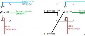
1. Black and white: to the ignition switch (short to ground) stop the engine. (On some models, not used if the switch is powered by a battery)2. Black-red: to the generator, power supply to the switch (In some models to the ignition switch +12)3. Green: mass4. Green: mass5. Blue-white: to hall sensor6. Yellow-black (sometimes orange): to the ignition coil.
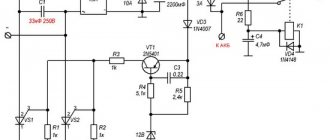
How to make a relay regulator with your own hands?
To make a relay regulator with your own hands, you need a diagram and a little knowledge. The model of a homemade regulator is based on the principle of disassembling the generator and outputting a separate end of the wire from ground.
As a diagram, you can take the relay-regulator connection diagram (Figure 3), and on its basis assemble a single-phase generator.
To collect the stabilizer you need:
- disassemble the generator and remove the stator from the engine;
- then you need to unsolder the ground from the generator, solder a separate additional wire for the winding to it and bring it out. This wire will be one end of the winding. The second end is the generator wire;
- After removing the wires, you need to reassemble the generator in reverse order.
With this device, the generator has 2 wires (there should be 3 in total). You can connect the stabilizer according to this scheme:
Do-it-yourself relay-regulator manufacturing diagram
At the end of the process, you need to connect the yellow wire from the old regulator to the “+” terminal in order to obtain a constant voltage on the sides of the network. Check the resulting voltage regulator on the scooter. At this point, the process of creating a homemade device can be considered complete.
The relay regulator is a very useful thing and necessary for the normal operation of the moped. However, it requires attention and constant monitoring of its work. Therefore, if the device fails or its performance is unsatisfactory, it is better to replace it with a new one, the cost of which today ranges from 300 to 500 rubles.
Method for checking the voltage regulator of a scooter
Chinese scooters are designed in such a way that their relay-regulator, which is also called a voltage regulator, often burns out. The voltage regulator is an electrical circuit with 4 terminals for connecting to the scooter's electrical network.
A malfunction of the voltage regulator leads to very disastrous consequences:
At first, the instrument panel backlight lamps and the central low/high beam lamp burn out. This happens due to the fact that the voltage from the generator is not limited to 12 volts, which leads to the lamps receiving an increased voltage of 16 to 27 volts and higher. The voltage supplied to the lamps fluctuates and depends on the engine speed. Even at idle, the lamps shine so much that they blind, although they should shine at half their maximum brightness.
If you do not remove the malfunction of the voltage regulator and leave everything as is (many do this - they just drive without lights), then over time the battery will fail because its charging voltage exceeds the permissible one. If the voltage regulator is faulty, the battery receives a voltage of more than 15 volts, while the standard charging voltage should be between 13.5 - 14.8 volts. All this leads to the fact that the battery begins to leak - acid begins to penetrate through the valves. This is noticeable to the naked eye. And although when the normal charging mode is restored, the battery restores its operation, its service life is sharply reduced.
Also, if the voltage regulator is faulty, the battery stops charging correctly and loses its capacity. Therefore, it is not possible to start the scooter with the button. You have to start it from kickstarter.
I think it’s now clear how important it is to change a faulty voltage regulator on a Chinese scooter.
How to check the voltage regulator on a scooter? It is best (and most reliable) to do this without dismantling the voltage regulator itself. We will need at least some kind of multimeter with a voltmeter function. Any ordinary DT-830 or similar will do. What should be done? It is necessary to measure the voltage at the output of the voltage regulator.
How to check the charging relay, voltage regulator
In this video I will show you how to check
two-phase
relay voltage regulator
, also called charging relay...
How to check if the relay regulator on a motorcycle is working?
How to check
Is the bike's alternator working? — .
All measurements were carried out on a Chinese scooter ABM Storm L ZW50QT-16.
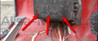
To get to the relay-regulator, unscrew the front fairing in which the central headlight is installed. We find there on the frame a box with 4 terminals: red, green, yellow and white.
We put the scooter on the stand and start it. After some time, the engine operation stabilizes at idle. Next, measure the voltage between the green and red wires. We set the multimeter in DC voltage measurement mode to the limit of 20V. Here's a look at how you can do it.
The display should display a voltage of about 14.6 - 14.8 volts, as in the photo. This is normal, standard voltage.
Then we need to measure the voltage that goes to the lighting lamps. The voltage to the central high/low beam lamp is not constant, but alternating (pulsating), so we switch the multimeter to the 20V alternating voltage measurement mode. On the multimeter that I used (Victor VC9805A+), you need to press the DC/AC (Alternating Current) button to do this. After this, we measure the voltage between the green and yellow wires. We simply move the probe from the red to the yellow wire, since the green wire is the common wire in the scooter’s electrical network.
The multimeter display should show a voltage of around 12 volts. It showed 11.4 - 11.6 volts. This is normal as the scooter is idling. If you have an assistant, you can ask him to accelerate a little to increase the engine speed and, consequently, the voltage from the generator. In any case, the voltage should not change much and should be around 12 volts.
This was a voltage measurement at the output of a working voltage regulator (relay regulator).
Now let’s see what a voltmeter shows when measuring the voltage at the output of a faulty scooter voltage regulator.
Scooter voltage regulator
Scooter voltage regulator
The voltage regulator on a scooter is also called a relay regulator - this is the most important part of the entire electrical system of the scooter, which, in addition to providing basic functions, helps the battery work longer and better. But the main task of the regulator relay is to ensure a stable supply of current that comes from the generator. After the current has arrived at the relay-regulator, the part begins to correctly distribute it to all the necessary devices, including light bulbs, batteries, sensors, indicators and others. In terms of its purpose, a relay can be compared to a transformer that receives and distributes electricity. Without it, the current will simply flow in the wrong amount, which threatens instant failure of all devices. Depending on the scooter model, the relay prevents the generator from producing a voltage higher or lower than the norm; in more frequent cases, this norm ranges from 12 to 14.5 volts. All current consumers (headlights, turns, sensors, etc.) are designed to use up to 12 volts.
It is also worth considering that initially the scooter generator produces an average of 30 to 35 volts, but when you start working, the 4t scooter voltage relay-regulator allows you to reduce this figure to an acceptable 12-14.5 volts. Another important task of this part is that it receives alternating current from the generator, turning it into direct current. If the voltage relay breaks down, you are at risk of rapid wear and tear of all electrical appliances; the light bulbs will burn out over time and will have to be replaced until they receive direct current in the maximum permissible amount.
What does a relay regulator look like?
This part is quite small in appearance; it looks like a small aluminum radiator. It works great with a thyristor that has a flat surface and is located under the radiator. The task of the thyristor is to normalize the voltage during surges above or below normal. The relay regulator is located in the front of the scooter under the front plastic, it is easy to find due to its noticeable appearance. If we take into account the part of Chinese 4t scooters, the characteristics of the part and its type are selected in accordance with the scooter’s devices, location and their characteristics. We strongly recommend that you buy a relay exactly for your scooter model, otherwise the connectors will not fit.
Checking the regulator relay on a scooter
If you notice that the light bulbs on your scooter often burn out, even after replacement, this happens after some interval, most likely your relay regulator is broken. But before replacing, you need to make sure of this by checking the part using a tester. To do this, we take a mechanical or electronic tester. First of all, you need to configure the device by turning on the “KiloOhm” mode. Next you will have to remove the relay from the scooter and measure the indicators at the terminals, which are marked in the picture below.
First of all, we measure the indicators of the AB terminals with a probe; they should show 18 kOhm. Next, we swap the probe and check the VA terminals; the tester should show 0 kOhm, that is, not react at all. If the tester starts to respond, the relay is most likely broken. After this, we check the LED outputs, the indicator should be within 33 kOhm. By swapping the terminals on the DC, the voltage should increase slightly, for example, to 42 kOhm. In other cases of ringing of the terminals, changing them (BP, DV, etc.), the tester should not respond to the action, the mark should indicate kOhm.
Important: this example of relay testing was carried out on a Japanese Honda brand scooter, so if you are the owner of any of the Tact, Dio or Lead models, feel free to check the serviceability using the above method.
How to replace a faulty relay regulator on a scooter?
If the charging current is not supplied to the battery contacts when the generator is working properly, the stabilizer needs to be changed. Replacing it yourself is not difficult.
To do this you need to do the following:
- Place the scooter on the central support.
- Find the location of the device in a specific moped model. If you can’t find it right away, you can use the instruction manual.
- Dismantle the cladding. Depending on the moped model, the stabilizer may be located on the front (under the front plastic), in the rear, or under the seat. In this case, the underseat space is removed along with the seat.
- Unscrew the device from its seat while maintaining the fasteners. As a rule, the relay is attached to the scooter frame with a bolt, or less often with a self-tapping screw.
- Disconnect the connector and secure the new regulator with the fastener. The installed device must have a pinout and connector similar to the one replaced, and be suitable in terms of parameters for this particular scooter model.
- Connect the relay-regulator on the scooter to a standard connector and assemble the remaining spare parts in the reverse order of disassembly.
How to check the scooter generator for serviceability
A failed generator blocks the operation of the entire scooter as a whole, since the entire scooter system is somehow connected to it. If there is a breakdown in the electrical system, a weak spark, or a poor battery charge, in addition to other equipment, a breakdown of the generator cannot be ruled out.
There are not many breakdowns in this case, these are:
- wire break (for example, due to wire breakage or fumes),
- short circuit ,
- significant reduction in the magnetization of the generator rotor.
Let's consider each of the points in more detail. For example, let’s take one of the Chinese scooters, since it is these devices that are most often subject to such breakdowns. What causes the rotor magnetization to decrease? This phenomenon can be observed due to an impact (for example, during a fall) or being near elements of a high magnetic field. As a result, the output current of the generator drops significantly during operation, and normal operation of the scooter is impossible.
Types of multimeters and the principle of their design
The most common types of multimeters are analog and digital. Let's look at how they are designed and work below.
Analog
These are old-style testers that look like boxes with a glazed arc-shaped scale and a spring-loaded pointer. Often there is a mirror arc on the scale so that when you look at the arrow you can align the arrow with its reflection. This way, when measuring, you are looking exactly perpendicular to the scale, rather than at an angle, and it will be more difficult for you to make a mistake. The measuring panel has many parallel arc scales for different types of measurements:
Analog multimeter.
One of the main advantages of an analog multimeter is its low price and measurement accuracy that is quite sufficient for everyday purposes. Moreover, most analog multimeters have a built-in special resistor to adjust the position of the arrow exactly to “0”. For adjustment, a resistor head is used, similar to a screw slot, located below the measuring scale approximately at the point where the arrow is attached.
Digital
These multimeters are more modern and look like oblong black boxes with a large liquid crystal display for digital readings. These devices got their name because the analog signals entering the device are converted into digital form in an analog-to-digital converter (ADC). Such devices are more expensive than analog ones, but their size and weight are somewhat smaller, and it is more convenient and faster to work with them.
Some models are well suited for working in complete darkness due to the ability to illuminate the indicator panel (and electricians often have to work in dark rooms). You simply press a button and the panel lights up. In addition, you can find a model with the ability to record the readings taken into the device’s memory and subsequently transfer this data to a computer for further analysis. To do this, just press a special button. Typically, digital devices are used by professional electricians, electronics engineers and engineers.
Digital multimeter.
The measurement kit includes two wires with terminals and pointed probes:
- one black wire – “minus”, “ground”, “com” (common);
- the second red wire is positive or “measuring”.
It will be interesting How to check a resistor with a multimeter
The black probe is usually applied to the body of the electrical appliance (common busbar) or attached with a special clip - an “alligator clip”. The red probe is most often taken in the right hand and applied to different places in the circuit. The probes included in the digital multimeter are the same as those in the analog multimeter. Often the sockets are color-coded - red and black frames, so as not to accidentally confuse which probe is inserted where.
Sometimes the multimeter is a built-in part of another device, such as a digital clamp meter. Due to the need to be large, such devices have a large amount of free space in their housing, where the multimeter is built in.
Scheme and principle of operation
The operation of the stabilizer for all models is almost the same and consists in distributing the current supplied from the generator to stabilize it and further distribute it to consumers.
The main peripheral consumers of the scooter include:
- battery;
- indicators;
- light bulbs;
- sensors;
- enrichment agent;
- other nodes;
- starting enrichment.
How does the stabilizer work? The main principle of its operation is to act as a transformer, which lowers the voltage to an optimal level acceptable for the operation of electrical appliances, and also stabilizes the network and prevents unexpected power surges.
To avoid these problems and their undesirable consequences, you should know the basics of the correct operation of the electrical circuit and voltage components of the scooter (Figure 1).
Voltage relay pinout diagram and wiring for main scooter models
The pinout of the relay regulator is standard for all models of Chinese-made scooters.
Scooter relay-regulator pinout
The stabilizer has an aluminum body and plastic contacts, each of which has its own wire. Each contact has its own wire color. This makes it convenient to connect the device to the wires if the plastic connector is worn out. The wires must be connected to the contacts according to the electrical diagram (Figure 3).
Design and principle of operation of a scooter generator
To the average person who is not experienced in electrical matters, a scooter generator may seem like a very complicated device. This is partly true: electric current is an invisible thing to the eye, and if we can see or touch mechanical faults, then we can only guess about faults in the electrics of a scooter or identify them using special measuring devices.
However, “it’s not the Gods who burn the pots” and if a person has a desire for something, then this article will be a good help, but for those who don’t want anything, there’s no point in continuing.
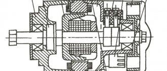
The scooter generator is a flywheel type generator with permanent magnet excitation. This type of generator is used on the vast majority of scooters, as well as mopeds and small motorcycles.
Designation of the main elements of the generator
The scooter generator consists of a rotor (in collective farm language - “anchor”) and a stator. The rotor is mounted directly on the crankshaft and while the engine is running, the rotor rotates around the stator coils
The stator is attached directly to the engine crankcase. And while the engine is running it remains motionless. The stator is a metal base made of several plates of special transformer iron. On the base of the stator there are special projections (coils) on top of which a copper wire is wound in a strictly defined order - forming the generator windings.
Depending on the generator model, there may be two or three windings. The generator shown below has three windings: supply, control and high-voltage
Permanent magnets are installed on the inner surface of the rotor. Magnets have different polarities. The magnets in the drain are covered with a lid; if you remove it, you can see them
Each magnet forms a static (constant) magnetic field around itself. In turn, the field of each magnet will be different: blue is negative (“north”), red is positive (“south”)
If we insert the stator into the rotor in the same way as is done on the engine, then we will see that the stator coils will be in the magnetic field of the magnets located next to them
After we start the engine, the rotor magnets will begin to rotate around the stator coils. During the rotation of the rotor, magnets of different polarities will approach the coils, which always stand still, and the field in which the coils are located will change at a very high speed. Due to the rapid change of magnetic fields, magnetic induction will occur in the generator coils and the generator will begin to generate electric current.
Current is good. But the current of a generator with excitation from permanent magnets is not a constant value and directly depends on the engine speed: the higher the engine speed, the more often the field of the coils changes - the induction increases and, as a result, the voltage in the coils increases. So it turns out that at idle engine speed the generator voltage will be 8-10V, and at maximum 60-70V.
In order to stabilize the generator voltage to specified limits, a special generator voltage regulating module was introduced into the scooter’s power supply system. That’s what it’s called: generator relay regulator
The principle of operation of the relay regulator is very simple: there are three windings on the generator stator: supply, high-voltage and control. The power winding is the main one and is designed to power the lights, sound signal and charge the battery.
The control winding is auxiliary and if the voltage in the supply winding increases, the relay-regulator supplies voltage to the control winding - the induction is disrupted and, as a result, the voltage in the supply winding of the generator drops.
When the voltage decreases, the opposite happens: the relay-regulator stops supplying current to the control winding, induction is restored, and the voltage in the supply winding increases.
The control and auxiliary windings of the generator are wound on the same coils
The high voltage winding is wound on individual coils or coil. The high-voltage coil is needed to form a spark on the spark plug and is only partially related to the generator. Rather, it relates to the ignition system, and this is a separate module and has little to do with the operation of the generator
Another auxiliary module of the generator is a load resistor. It is needed to ensure that the generator does not operate without load. For devices that generate current, working without a load is like death. The designers foresaw this possibility in advance and, in order to prevent the generator from running idle, they slightly loaded the supply winding onto the resistor
In addition to the elements described above, the scooter’s energy supply system includes an ignition sensor, which, at the right moment, ensures the formation of a spark at the spark plug.
This module is the same generator only in miniature and it works exactly on the same principle
On the outside of the rotor there is a small magnet in the form of a rectangular protrusion. This magnet, just like its larger brothers, forms a constant magnetic field around itself, and what happens next, you probably already guessed: while the engine is running, the field passes through the sensor coil and a small current is generated in it, which goes directly to the switch, controlling the torque in it sparking
Setting up and testing the scooter
Check the power interrupt switch. This safety feature "interrupts" engine power when you apply the brakes. If your scooter does not work after adjusting the brakes, then the problem lies in this unit.
Adjustment procedures may vary depending on the scooter model. You can usually loosen the brake adjustment tension by turning the brake adjuster built into the handle toward the lever. This releases the tension on the adjustment and safety switch. Check the owner's manual or contact the motor manufacturer.
If this setup doesn't work, there is an easy way to test the generator. Disconnect it from the controller, then try to start the scooter. If the problem is with the switch, then the scooter will only work when the brake lever switch is disabled. Make sure the power switch is turned on.
How to check the voltage regulator of a scooter?
To check, you need to stock up on a multimeter that has a voltmeter function. It is needed to measure the voltage at the output of the voltage regulator.
To measure the voltage, you first need to get to your destination. To do this you need to remove the front fairing. As a rule, it is fastened with several nuts and rivets (for example, on a Honda dio there are 3 nuts and 4 rivets)
We remove the fairing carefully, it is easy to damage. There we need to find a small box in which there are 4 outputs (some scooters have 5 outputs)
The outputs have the following colors: green, red, yellow and white.
In order to measure the voltage, the scooter must first stabilize in operation, that is, the idle speed must be stable. You can put it on the step, start it and wait for it to stabilize. If the scooter does not start or does not hold idle, then read the article: the scooter does not hold idle. If everything is fine, then you need to measure the voltage between the red and green wires. We set our measuring device to 20V, constant voltage measurement mode. If the voltage is within 14.6 - 14.8, then this is the normal voltage of the relay regulator. If the regulator is faulty, then this value can fluctuate even by 5V or more in any direction. If the value is less than 14.5V, or exceeds 15V, then the regulator is faulty.
Now you need to check the voltage supplied to the lighting. Since alternating voltage is supplied there, we set our multimeter to measure alternating voltage 20V. To measure the voltage supplied to the lighting, you need to measure it between the green and yellow wires. As a rule, the norm for lighting is a voltage of 12 volts; most incandescent light bulbs are designed for this voltage. Allowed + – 0.5 volts. Do not forget that the scooter operates at idle and if you add speed, the voltage will rise, but it is not permissible for the voltage on the regulator to rise to 13+ volts. If the regulator is faulty, the voltage may rise higher. For example, up to 15-16V, but even 13 volts of voltage is harmful for incandescent light bulbs. The regulator is clearly faulty. Especially considering that this is at idle engine speed.
If you see that the voltage regulator is faulty, you need to urgently replace it. Otherwise, very soon other devices will be added to it that simply could not withstand the high voltage.
A 4t scooter voltage regulator relay can be bought for 500 rubles.
How to check PP with a multimeter on a moped?
The relay regulator on a Chinese scooter is checked using a multimeter with a voltmeter function. For this purpose, a simple DT-830 (or equivalent) is usually used. It is better to carry out diagnostics and measurement of output voltage with the device removed.
Verification algorithm:
- You need to unscrew the fairing with the central phase and find on the frame a device with 4 wires: red, green, yellow and white.
- Then start the scooter and check the voltage at idle: measure it between the green and red wires, setting the multimeter to the maximum value of 20 V.
- If the multimeter display shows a figure of 14.6-14.8 V, this is normal. For stabilizers on Chinese mopeds, this is the operating standard voltage. If at idle the multimeter shows a value of 15-16 V, this is a high voltage indicator. This indicates a malfunction of the relay regulator.
- Then you need to check the voltage supplied to the lighting lamps. An alternating voltage is supplied to the central low beam (high beam) lamp, so the multimeter should be switched to the alternating current measurement mode with a parameter of 20 V.
- Next, we measure the voltage between the green and yellow wires (green is the general electrical network of the moped). If the multimeter shows a network voltage of up to 12 V, then the electrical appliances are operating without additional load.
- If at idle this value is 16 V or higher, and with a sharp increase in engine speed it jumps to 25 V, the device does not stabilize the voltage and, therefore, does not work. With such readings, the device must be replaced with a new one.
Checking the VAZ 2107 regulator
Until 1996, classic VAZ 2107 cars with a cipher generator 37.3701 were equipped with an old-style voltage regulator (17.3702). If such a relay is installed, then it should be checked as on the top ten (discussed above).
After 1996, they began to install a new generator of the G-222 brand (there is an integrated regulator RN Ya112V (B1).
Checking the regulator separately
- 1 - battery;
- 2 - voltage regulator;
- 3 - control lamp.
To check, you need to assemble the circuit shown in the figure. At a normal operating voltage of 12 V, the light bulb should just glow. If the voltage reaches 14.5 Volts, then the light should go out, and when it drops, it should light up again.
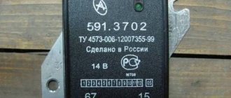
Checking relay type 591.3702-01
Relay test diagram:
Such old relay models are sometimes installed on the classic VAZ 2101-VAZ 2107, on GAZ, Volga, Moskvich cars.
The relay is mounted on the body. It is checked according to the same scheme as the previous ones. But, you need to know the contact markings:
- “67” is the minus (-) contact.
- "15" is a plus.
The verification process is the same. At normal voltage, 12 Volts and up to 14 V, the light should light. If lower or higher, the light should go out.
PP-380
The RR-380 brand regulator was installed on VAZ 2101 and VAZ 2102 cars. Adjustable voltage at the temperature of the regulator and the environment (50±3) ° C, V:
- at the first stage no more than 0.7
- at the second stage 14.2 ± 0.3
- Resistance between plug “15” and ground, Ohm 17.7 ± 2
- Resistance between plug “15” and plug “67” with open contacts, Ohm 5.65 ± 0.3
- Air gap between armature and core, mm 1.4 ± 0.07
- Distance between contacts of the second stage, mm 0.45 ± 0.1.
Testing a three-level relay
As the name suggests, such relays have three voltage levels. This is a more advanced option. The voltage levels at which the battery will be disconnected from the voltage regulator can be set manually, for example: 13.7 V, 14.2 V, 14.7 V.
How to check the generator
To check functionality, you need to:
- Disconnect the wires going to terminals 67 and 15 of the regulator.
- Connect a light bulb to the wires. Bypassing the relay.
- Disconnect the positive terminal of the battery.
If the car does not stall, then the generator is working.
Scooter electronic ignition device
The modern ignition system of a 4t scooter is designed as follows: the switch and coil, which are its main elements, supply high voltage to the spark plug, which generates an electrical discharge that can ignite the fuel. The coil generates high voltage due to electromagnetic induction. The switch is needed to distribute its interruption voltage at the right time. Inside there is an electronic circuit, a thyristor and three outputs for wires. At the right moment, the switch supplies voltage or turns it off.
The principle of operation of the scooter ignition system is as follows: the battery supplies voltage to the coil, which is often connected to a switch in one unit, the switch supplies voltage to the spark plug, and decides when to interrupt it. The mixture in the cylinders lights up at the right time. The correct operation of the engine and whether it will start at all depends on how the ignition is configured and set.
Switch
In many scooter models, the commutator is combined with a coil, so if one of the devices fails, the entire unit has to be replaced. Such spare parts are inexpensive.
Externally, the switch looks like a plastic box. Inside there is a microcircuit, a variety of electronics that cannot be repaired. In addition, there is a thyristor. The task of this element is to interrupt the electrical impulse at the right moment; for this purpose it has three outputs. When current enters one of them, the thyristor turns into a conductor, and the current moves from the input contact to the output. When a certain voltage is reached and the current drops, the pulse is interrupted, after which the Hall sensor returns the thyristor to its original position so that the signal arrives again at the third output. The process is repeated every time the voltage is applied again.
How to check the generator on a scooter?
The scooter generator is one of the most important parts of the scooter; its malfunction means that it is impossible to continue moving; a spark simply will not appear.
But if you doubt whether your generator is working or the reason for the malfunction of the scooter is in another part, it is strongly advised to check the generator. Many people don’t know how to check the generator on a 4t scooter, because this relates more to electrics, which scooterists hardly understand. Also, the verification problem will be in the absence of the main tool - a multimeter tester. Experts identify several reasons for generator failure:
- short circuit formation;
- mechanical failure or wire breakage;
- significant reduction in rotor magnetization.
Before checking the generator for serviceability, we will consider the main faults. Practice shows that the generator breaks down most often on Chinese scooters, where the most common failure is the rotor losing its magnetization. The rotor often loses magnetization precisely because the scooter falls, that is, there is a direct impact. Also, if there is a nearby magnetic field, the rotor discharges.
To check the charge on the generator, you will need to use a proven method; the main task is to find out the output voltage. First of all, completely disconnect the generator from the scooter, then use the control device and start the engine. After starting, you can check the output voltage; the working generator should show at least 5V with the engine running.
The second stage is checking the output voltage of the switch; for this you will need a multimeter. The testing process begins by connecting the commutator to the generator stator, this is done using wires from both parts. Then you need to disconnect the wire related to the switch block from the ignition coil winding terminal. The next step is to connect two terminals - one goes to the engine ground, the second to the main wire on the ignition coil. This main wire is connected to the commutator.
After this, you will have to set the voltmeter to the main “direct current” mode and crank the engine with the kickstarter. By these actions we can find out the output voltage of the switch to the ignition coil. Then connect the switch wire to the coil. Under normal conditions, the output voltage of the scooter should be 200 V. For many, such a test may seem too complicated, because most of the terms are unfamiliar, and not everyone can use a multimeter, but if you really want, you can try and check the generator on a Chinese scooter.
Using a multimeter, you can find out the presence of voltage and its indicators, so you will have to start the procedure by removing some parts of the plastic located in the engine area. On the scooter you will have to find a large bundle of wires, which is located on the engines. Find the wire that should connect to the generator. The next stage is to measure the parameters of the circuit, the main task of which is to power the generator coil with electricity. Important: before this test you will have to disconnect the wiring from the generator, after which you can check the resistance. In normal operating condition, the generator should produce a resistance of 80 to 150 ohms. Deviation from the norm indicates a malfunction of the generator and the need to replace it. In some cases, the presence of incorrect resistance lies in the wiring, which is faulty. This can be determined by removing the generator and checking the coil resistance separately; if it gives optimal data, the reason is in the wires, in particular their short circuits.
Detecting the above faults is not an easy task; most scooter owners are not able to check the generator for serviceability, which is why they turn to specialists. If you have the financial means, it’s easier to buy a new generator, so you decide how to solve this problem yourself.
Signs that a check is needed
If the battery on your scooter often runs out, and it is still quite new, this means that there is a problem with the operation of the relay regulator. As practice shows, it burns out quite often. If the device is faulty, the battery stops charging completely and loses its capacity. This means you won’t be able to start the scooter with a button; you’ll have to start it with a kickstarter.
Another characteristic sign of incorrect operation of the device may be the frequent burnout of incandescent light bulbs. They themselves are durable and have a good durability, but are quite sensitive to voltage changes. This happens because the optimal voltage in the scooter network is considered to be 12-13 V. Increasing this value even by 2 V reduces the service life of electronics and components by 2 times.
The greater the deviation from the norm, the greater the likelihood that something will burn out in the scooter. Therefore, when starting the scooter from the starter due to a power surge and a faulty relay, the bulbs usually burn out.
Signs of a malfunctioning regulator are identical for all models of Chinese scooters. They are especially typical for charging relays for scooters of Chinese models with an engine capacity of 50 cc. Therefore, before making a decision to replace something in electronics, testing systems and devices should begin with the relay regulator.