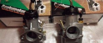
The “Tourist” and “Tulitsa” scooters use horizontal carburetors K-28, K-36, K-62. When choosing a model for better engine performance, 2 parameters are taken into account: the diameter of the diffuser (25-27mm) and the throughput of the main jet (180-210cm3/min). The optimal carburetors are with the index “G”.
The K-28G carburetor with a horizontal mixing chamber housing was installed on motor scooters. The carburetor throttle valve moves horizontally. This is the main difference between the K-28G carburetor and the K-28B carburetor, but they work the same way. The K-28 carburetor is adjusted as follows: start and warm up the engine. Set the fuel adjuster lever to the “you” position. By unscrewing or screwing in the throttle valve thrust screw, set the minimum possible engine speed. Tighten the fuel mixture screw as far as it will go, and gradually unscrewing it until the engine runs smoothly and steadily. Repeat the last two operations until the engine stops responding to changes in the position of the fuel mixture screw or stalls. Turn the fuel mixture screw 1/3 of a turn and tighten with the locknut.
Setup and adjustment
First of all, the engine warms up until the fan turns on.
Next, adjust the speed by ear using the quantity screws. The operation should be smooth, with a sharp press on the gas pedal there should be no dips, and the speed should increase quickly and smoothly. The quality screw regulates the amount of exhaust gases. Ideally, no escaping gases should be visible from the exhaust pipe in the dry season (they will be, but not visible to the eye, if everything works correctly). Everything can also be done by looking at the tachometer readings. Unfortunately, many models of Soviet cars do not have it at all, so most often the adjustment will have to be done by ear. For complete adjustment, cleaning and tuning, the carburetor is removed from the car. Procedure for removing the device from the car:
the air filter and its housing are removed;
all tubes and cables are disconnected;
the EPHH wiring is removed;
the nuts are unscrewed.
If you are not sure that you will be able to put everything back, you can photograph all fastenings before disconnecting, for example, with a mobile phone camera.
Take care of the place where the work will be performed. It should be ventilated, free from various suspensions, the table should be wiped and covered with a cloth or old newspapers. It is better to have a carburetor diagram before your eyes. It is advisable to place small parts in various jars and boxes strictly in order. Prepare a container for solvent brand “646”. Buy a repair kit for your carburetor, it costs mere pennies.
Operating procedure:
look at the floats. They must be parallel to each other. If there is any mechanical damage, replace it with new ones without hesitation. The needle valve should move freely in the seat, and the ball should not linger anywhere;
We wipe the lid from the inevitable dirt and oil, for this we use a bath of solvent. You can leave it to “settle” for a while;
- the starting device is simply wiped, otherwise the correct operation of all kinds of bushings and levers can be disrupted;
- The jets and tubes are cleaned with a solvent and then blown out with compressed air. When flushing the jets, remember that it is highly not recommended to use rags, rags, etc., since the holes become clogged very easily;
The body is cleaned in a similar way: throw it in a solvent and let it soak, then blow it out. If you notice any damage in the contact areas, you will have to replace it entirely;
The next step is to inspect the accelerator pump. Likewise, jamming and subsidence are unacceptable, the ball must move without difficulty;
The economizer should move easily and the diaphragm should not be damaged. If there are suspicions, we replace it with a new one from the repair kit;
- reassemble in reverse order. At the same time, we use new gaskets, rings, studs, and change the fuel filter. It is better to leave new jets until better times, if there were no questions about the previous ones, since there is a high probability of making a mistake, and defects in repair kits are common;
- We install the carburetor on the car, connect all the pipes and try to start. The first time it may not work, although this is a rare occurrence, it usually starts right away, however, it will work unstable. If the assembly order was followed, it does not matter;
- In order not to get lost, we tighten the quality and speed screws to the end.
The further adjustment procedure is similar to the actions taken before removing the carburetor and washing and replacing faulty parts. Normal speed of a fully warmed up car: 800-900 in winter, 900-1000 in summer.
In conclusion, we can say that the Solex carburetor is one of the best, if not the best, among all domestic products. With proper setup and timely maintenance, it will show excellent results throughout its entire service life.
Solex 21083 carburetor jet table
Also watch the video on setting up the Solex 21083 carburetor
Carburetor K-28
Device repair and adjustment of carburetor for 151C
The K-28 carburetor is installed on IZH-350 motorcycles. A quencher is placed in the float chamber cover. The float chamber is connected through a channel to the well in which the main jet is installed. Using the low-speed channel, the well communicates with the mixing chamber through two holes, with one hole in the channel coming out behind the throttle valve, and the other in front of it. In addition to the exits to the mixing chamber, the low-speed channel communicates with the atmosphere. The flow area of the last channel is adjusted using a conical screw, and the outlet hole is covered with a small mesh filter.
The main jet is screwed into the atomizer, which in turn is screwed into the mixing chamber body. The upper part of the well communicates with the atmosphere through a wide channel, which originates at the inlet of the mixing chamber.
The throttle valve of the K-28 carburetor has the usual cylindrical shape for motorcycle carburetors. The damper is lifted by tensioning a cable connected to the rotating handle of the steering wheel; the throttle valve is lowered under the action of a spring located around the cable and its upper end resting on the lid of the mixing chamber, and its lower end on the upper part of the throttle valve.
In addition to the throttle valve, an air damper (air corrector) is installed in the mixing chamber. This valve runs in a slot at the rear of the throttle and is also controlled by a cable and spring. The cable is connected to a lever (shifter) on the steering wheel. By operating the lever you can raise or lower the air damper. Adjusting the length of the sheath of the cables that control the dampers is carried out by screwing in or unscrewing the thrust bushings, which in turn are screwed into the mixing chamber cover.
The K-28 carburetor operates on the principle of mixed fuel regulation. Let's consider the operation of this carburetor at different engine operating modes.
When the throttle valve is closed or slightly open, fuel is supplied through the low speed channel. At the moment of rarefaction, the fuel begins to rise from the well and mix with air, which, as already mentioned, can enter the low-speed channel in two ways: through the hole, which is under atmospheric pressure in the initial stage of opening the throttle valve, and through the hole, which communicates directly with the atmosphere.
From the above it is clear that fuel from the low speed channel enters the mixing chamber mixed with air, i.e. in the form of a ready-made mixture. As the throttle valve opens, the vacuum begins to spread to the low speed channel outlet located behind the throttle valve, from which the emulsion also begins to flow. With further opening of the throttle, since the resistance of the low-speed channels is relatively high, fuel stops flowing from them and begins to leave the atomizer. The flow area of the sprayer is adjusted by a needle. The higher the needle is raised, i.e., the more the throttle valve is open, the wider the nozzle cross-section and the more fuel flows. When the damper rises above its full stroke, the braking effect of the needle stops, and from that moment on, the amount of fuel entering the atomizer is determined only by the flow area of the main jet. To adjust the height of the throttle valve at idle in order to obtain the desired engine speed when the throttle is fully closed, a thrust screw is screwed into the mixing chamber housing, with which the engine operation is regulated to the desired low speed.
The air corrector is designed to enrich the mixture during engine startup and warm-up periods. Under normal conditions, with a normally adjusted carburetor, there is no need to use an air corrector while driving: the carburetor must, without its help, ensure correct operation of the engine in all modes.
Adjusting the K62 carburetor
06/16/2021 NEMEC
74387
The carburetor is one of the main components of a motorcycle, which affects the operation of your bike’s engine. Its correct adjustment affects how it starts, runs, and engine power. The second element is the ignition system. In this article we will talk about adjustments that can be found on motorcycles Minsk, IZH Jupiter and Planet, Voskhod.
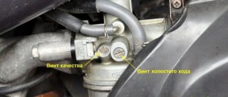
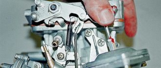
The K62 carburetor has two adjusting screws, with which you can change the idle speed, and a needle, by changing the position of which, you can change the property of the mixture (enrich or lean it). When we raise the needle, we enrich the mixture; when we lower it, we make it leaner. Adjusting the quality of the mixture is carried out by walking 2-3 km (at a speed of about 60-70 km/h) and looking at the spark plug. If the candle is covered with the working mixture (the candle is oily, dark brown or black), we lower the needle; if it is too dry (the color is white, light straw), we raise it. As a result, a light brown soot should appear. But this is just part of the adjustment; each time you need to set the carburetor idle speed. So we continue to adjust further:
To adjust the idle speed on the K62 carburetor there is a “quality screw”. This screw supplies air even when the throttle is closed. We repeat, the propeller produces air, although some people think that this propeller is designed for fuel. Therefore, by tightening the quality screw, we close the air flow, that is, we enrich the mixture. If we unscrew the screw, the mixture becomes leaner. As was said, this screw provides air in all positions of the damper, and therefore at idle speed of the crankshaft. Therefore, the quality screw belongs to the idle air regulator. At this moment, it significantly affects the operation, but if the gas is at medium or high speeds, then the influence is not large, but it is present. So, it all comes down to the fact that the idle speed is adjusted, and this automatically affects all engine frequencies. Now, after a short introduction, let’s talk about the idle speed adjustment itself. To keep things simple, let’s talk about adjusting K62 K carburetors and similar ones for Minsk and Voskhod motorcycles. But by analogy, the adjustment of all types of carburetors is the same, so it will also work on IZH and other motorcycles.
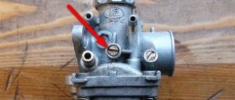
Remember that carburetor adjustment always takes place on a warm engine. When the warm-up is done, we begin the adjustment. First, tighten the quality screw to the maximum and unscrew it halfway - one turn. Next, we start the motorcycle and lower the throttle completely with the upper idle screw, then, by unscrewing it, we achieve the minimum stable speed. Next, by unscrewing the quality screw little by little, we achieve maximum speed; when, after further unscrewing, the speed drops, we screw it back to the same maximum and stability. It turned out that we set a stable idle speed at these minimum speeds. But the idle speed is most likely too high, so we lower the throttle with the upper screw, achieving even lower speeds. We tighten it down to the very minimum, when at even lower crankshaft speeds the motorcycle begins to stall. Having established the minimum at which the motorcycle still works, we repeat the procedure again with the quality screw. By screwing in and unscrewing the screw we achieve stability. Then we lower the damper again, making a higher minimum of crankshaft revolutions and so on until the crankshaft begins to operate at the lowest frequencies. When we have completed the adjustment, we can check the idle for stability. To do this, take and sharply turn the throttle to maximum and look at the speed at which the revolutions increase. After increasing, we sharply lower the gas and listen to the engine again. If the idle speed adjustment is done correctly, then with such a sharp increase and decrease in gases, the motorcycle engine should listen to the throttle at the moment and also sharply increase and decrease the crankshaft frequencies. When the engine lags, it means the adjustment is slightly incorrect. In such cases, you can try to do everything all over again, but you can simply add or reduce air at idle. If, with a sharp increase in gas, the engine does not respond immediately or even stalls, it means that the screw should be tightened 1/4-1/2 of a turn. In case of poor performance in cases of sudden release of gas, the screw must be unscrewed 1/4-1/2 turn.
How does a carburetor work?
Repair and cleaning of VAZ 2109 carburetor
The carburetor design includes several additional systems that help correctly.
- The main additional system is the carburetor trigger; without it, it simply will not work, which means there will be no fuel for combustion.
- The second system is the idle system. This system ensures that the internal combustion engine operates while the car is stationary.
- Well, the last main system here is the accelerator pump and the system for dosing the fuel composition.
- There is another system that sucks air into the system using a special piston and an air duct opening. The carburetor especially needs air to mix it with fuel. But before entering the carburetor, air and fuel pass through a special filter. This is necessary in order not to damage or clog all the holes.
The filtration system is one of the main parts with which the carburetor engine power system is equipped. This system is very important for protecting the internal combustion engine from clogging, because the air contains dust and other small particles. There are many types of filters, but they have the same principle and purpose. The whole principle is based on the fact that air with various particles passes through meshes, holes and other obstacles and is cleaned, leaving all the debris on the obstacles. Using the same principle, gasoline undergoes filtration before it ends up in the tank. There are many different diagrams on the Internet that show the principles of operation of systems.
A carburetor engine, like any other, is equipped with a pump that accelerates the supply of fuel, a fuel mixture metering device and an idle system. The carburetor works in such a way that before entering the cylinder, the air passes through the mixing chamber, where it takes fuel particles with it, after which it is sent into the cylinder, because the piston moves down and opens the intake valve.
GUYS, help! what kind of carburetor?
lol I was looking for info on the carb, I found this post, I have one on IZh49, I just washed it, polished the insides (and a little bit on the outside)
Design and operating principle
Design and adjustment of the OKA 11113 carburetor
Design
The carburetor supplies the engine with a fuel-air mixture in various modes. When starting from a “cold” state, the throttle valve is manually fully opened (the so-called “choke”), and the mixture entering the cylinders is completely enriched. After the engine warms up, the speed drops and the choke can be removed. Drivers remove it in different ways, but it is recommended to do it gradually.
The fuel in the carburetor is transferred to the float chambers from the diaphragm pump, and the needle valve controls the gasoline level. Through the chamber, the fuel passes into the channels of the body, where it enters the nozzles, and through them it goes into the first chamber. A fuel-air mixture is formed, which is supplied directly to the cylinders by the gas pedal. The second camera turns on only during sharp acceleration and operation at high speeds.
At idle, the IACV (idle speed solenoid valve) is turned on, while the engine runs stably and the car consumes much less fuel. However, on some devices it can be disabled; if it breaks down, the speed and consumption will only increase slightly, but the car will drive.
Idle air solenoid valve
What is this thing for?
What is this thing for? When you pump it up, it sometimes leaks gas, and what happens if you connect it together??
2↑ Reply from Sergey-rus52 11/23/2011 11:18:17
- Registered: 09-02-2011
- Messages: 540
- Reputation: 9
Re: What is this thing for?
they need to be connected together according to the idea
3↑ Reply from Valentin23 11/23/2011 11:21:45
- From: Altai region Slavgorod
- Registered: 24-10-2011
- Messages: 432
- Reputation: 6
- Motorcycle: IMZ 67-36
Re: What is this thing for?
So I’m asking what will change if you connect, the instructions don’t say anything about this
4↑ Reply from jipss 23-11-2011 14:05:13
- From: Gornozavodsk, Perm region.
- Registered: 18-07-2010
- Messages: 2 521
- Reputation: 186
- Motorcycle: Ural 'grom', Ural M72m, cross M-104, forest IMZ with sidecar.
Re: What is this thing for?
Yes, almost nothing, maybe the consumption will change a little, but more or less is different for everyone
5↑ Reply from Shaman 23-11-2011 16:36:12
- From: Teykovo 37 region
- Registered: 13-02-2011
- Messages: 1 346
- Reputation: 86
- Motorcycle: imz 8.103-40, dnepr 11
Re: What is this thing for?
so you can just mute it
6↑ Reply from Messer_SS 23-11-2011 18:23:44
- From: Tambov
- Registered: 05-09-2010
- Messages: 3 821
- Reputation: 328
- Motorcycle: There are many of them.
Re: What is this thing for?
I switched and don't regret it
7↑ Reply from Likan 23-11-2011 20:45:12
- From: Moscow region Naro-Fominsk
- Registered: 22-01-2011
- Messages: 681
- Reputation: 78
- Motorcycle: Ural with sidecar
Re: What is this thing for?
This is the balancing channel of the float chamber with atmosphere. you just need to leave it alone and not attach/connect anything to it.
from the manual: The carburetor is equipped with a balancing system, which consists of many channels connecting the above-fuel space of the float chamber with the atmosphere. The task of this system is to provide constant, close to atmospheric, pressure in the chamber (and therefore at the entrance to the dosing systems). The balancing system is equipped with a fitting, which allows using a hose to drain excess fuel from the carburetor (for example, when using a quencher) into a reserve tank, and not into the ground.
Edited by Likan (23-11-2011 20:47:28)
8↑ Reply from Messer_SS 23-11-2011 20:53:29
- From: Tambov
- Registered: 05-09-2010
- Messages: 3 821
- Reputation: 328
- Motorcycle: There are many of them.
Re: What is this thing for?
This is the balancing channel of the float chamber with atmosphere. you just need to leave it alone and not attach/connect anything to it.
from the manual: The carburetor is equipped with a balancing system, which consists of many channels connecting the above-fuel space of the float chamber with the atmosphere. The task of this system is to provide constant, close to atmospheric, pressure in the chamber (and therefore at the entrance to the dosing systems). The balancing system is equipped with a fitting, which allows using a hose to drain excess fuel from the carburetor (for example, when using a quencher) into a reserve tank, and not into the ground.
You write correctly. But there is one BUT: this is a manual for 68 carburetors on 2-stroke engines in which the carburetors stand vertically and without tilting. Through my trial and error experience, I came to the conclusion that it is necessary to bridge them with each other using a capillary (good for car washers). I installed these carburetors after the killed 301s. They were praised to me for their meager consumption, etc., etc. I filled in about 2 liters and it quickly gobbled up my fuel. I got upset. Then, by chance, in one of the long turns, I noticed that when I leaned to the right side, this right carb fitting It’s just that gasoline is simply pouring out. At the same time, the level in the float chamber was set. In the end, I shorted it and I don’t regret it. But it’s up to you to decide.
Preparing for the setup procedure
Before adjusting the carburetor, you need to familiarize yourself with the rules of the procedure. Individual configuration must be carried out in a strict sequence of actions. This will avoid repeated adjustments.
Before you begin making adjustments, you need to thoroughly inspect the carburetor. Its parts should be cleaned of dirt
It is very important to wash the strainer and float chamber. It is also recommended to clean the air jets
Only after these procedures can you begin setting up the unit.
You can start adjusting only when the engine has completely warmed up to its operating temperature. If your car's engine is unable to warm up properly, it will not be able to operate normally. Only if the engine is warmed up will you be able to correctly adjust the CO content in the car's exhaust.
The video shows how to clean and adjust the carburetor:
The engine should run for about five minutes. After that, you can turn it off and get to work right away. Remove the fuel hose in advance to prevent gasoline from spilling into the chamber. Unscrew the five screws on the carburetor cover itself and remove the choke cable. Then you can open the lid - strictly horizontally - to begin the adjustment process.
Carburetor care and adjustment
Within the time limits specified in the article - “Car Maintenance”, it is necessary to remove sediment from the carburetor and clean it.
The carburetor must be washed with clean gasoline or acetone, followed by blowing with compressed air.
The carburetor can be equipped with a fuel supply valve and an economizer valve with an elastic shut-off element (made of special rubber), so flushing with acetone or solvents based on it should be carried out only after unscrewing these components from the carburetor body parts.
Knocking on the valve and squeezing the seat with the valve are not allowed.
When disassembling the carburetor, removing the upper housing, it is necessary to unscrew the hollow screw 14. It must be taken into account that the discharge needle valve 40 is not secured and may fall out of the housing.
It is strictly forbidden to use wire or any metal objects to clean jets, injectors, channels and holes.
It is prohibited to blow compressed air through the assembled carburetor through the fuel supply hole and the balancing tube, as this will damage the float.
When storing carburetors for a long time, measures must be taken to protect them from corrosion, contamination and damage.
Pneumatic centrifugal maximum speed limiter
The maximum number of revolutions of the engine crankshaft is limited by a pneumatic centrifugal limiter, consisting of two mechanisms: a centrifugal sensor rotating from the engine camshaft, and a diaphragm actuator that acts on the carburetor throttle valves.
The sensor consists of three main parts: housing 25, cover 19 and rotor 22. The cover and housing are connected with screws; for sealing, a gasket is installed between them.
The cover contains a sealing gland 18.
A metal-ceramic porous bushing 24 is pressed into the sensor body, for the lubrication of which a wick 23 impregnated with oil is provided.
The sensor rotor contains valve 27, valve seat 28, adjusting screw 20 and spring 14. To access the adjusting screw, a hole is provided in the sensor body, closed by plug 21.
The sensor must be lubricated in accordance with the lubrication chart.
When the engine is running from the mixing chamber through jets 2 and 4 into cavity “ B”
a vacuum is transmitted, under the influence of which air begins to flow from the carburetor air neck through hole 10.
Air passes from the air neck into cavity " B"
through hole 10, tube 13 connecting the carburetor air neck with the side hole of the sensor housing, hole in the valve seat 28, channel 26 in the rotor axis, tube 12 connecting the central hole of the sensor housing with the diaphragm mechanism cover.
The vacuum created in cavity “ B”
above the diaphragm is small, and the throttle valve shaft rotates freely in the direction of their opening under the action of spring 5.
If a certain number of revolutions to which the centrifugal sensor is adjusted is exceeded, valve 27, under the influence of centrifugal force, overcomes the tension of spring 14 and partially closes the hole in the valve seat 28, thereby changing the air flow from the air neck into cavity “ B”
above the diaphragm.
The vacuum from the mixing chamber through jets 2 and 4 is completely transmitted to the space above the diaphragm, as a result of which the diaphragm moves upward, overcoming the tension of spring 5 and closing the throttle valve.
Cavity " A"
connected through hole 9 to the carburetor air neck.
When closing the throttle valves, the flow of the combustible mixture into the engine cylinders is reduced, as a result of which the engine does not exceed the specified speed.
The speed limiter is adjusted at the factory to a specified maximum speed, and its adjustment is not allowed to be changed during operation.
Carburetor P-23U ChTZ
To prepare the combustible mixture on the starting engine, a K 125L carburetor with remote control is used, designed to work with a single-mode speed controller. The carburetor diagram is shown in Fig. 107.
Removing the carburetor
Close the tap of the gasoline tank and disconnect the gasoline supply tube 1 (Fig. 108) from the carburetor.
Disconnect control cable 2 from the bracket and choke lever, control cable 3 from the bracket and lever 5 for limiting the carburetor throttle travel. Disconnect the regulator rod 9 from the throttle valve lever 6 without changing its length. Remove the air cleaner from the carburetor by loosening the clamp 4, unscrew the two fastening nuts 7 and remove the carburetor shield and the carburetor with flange gasket 8 from the studs of the suction manifold.
Disassembling the carburetor
Unscrew six screws 31 (Fig. 109) and remove cover 32 of the float chamber assembly.
Remove gasket 19 of the cover. To wash and clean the filter mesh 22, unscrew the plugs 21 and 23. To wash and purge the fuel supply valve, remove the float 20, remove the float axis 26, remove the needle 25 and unscrew the valve 24. To wash and purge the channels and jets of the carburetor, unscrew: the idle air jet stroke 29, accelerator pump nozzle 28, plug 14, main jet 15, two plugs 4 and 5, idle fuel jet 6 and main air jet 7, idle screw 1, shaped plug 18; remove: emulsion tube 16, valve lock 9, discharge valve 10.
Unscrew the nut 35, remove the lever 36 of the accelerator pump drive, disconnect the earring 33 from the rod 34 and remove the accelerator pump drive assembly 8. Remove the locking ring 11 and the check valve ball 12.
Unscrew the two screws 3 and remove the mixing chamber 2 with the flange gasket.
Technical requirements for the carburetor
- The fuel level in the float chamber at an excess pressure of 19.6 kPa (0.2 kgf/cm²) for gasoline with a density of 720.750 kg/m³ should be within 18.5. 21.5 mm from the top plane of the float chamber, which corresponds to the reference size T = 39 mm from the bottom surface of the float to the plane of the float chamber cover. Check the T dimension on the float chamber cover with the float facing up. Adjust by bending tongue K. After this, set the valve needle stroke within 1.2. 1.5 mm by bending the tongue M. The needle stroke is determined by the gap between the needle 25 and the tongue K in the position of the float, raised up until the tongue M stops in the bracket 27.
- The float must be sealed. When the float is immersed in hot water with a temperature of 333–343 K (60–70 °C), no air bubbles should come out.
- Individual adjustment of the following parts and assembly units is allowed:
- throttle valve - to ensure a circumferential gap between the wall of the mixing chamber housing and the valve in the closed position of no more than 0.06 mm;
air damper - to ensure a gap in the closed position of no more than 0.2 mm.
- The spring 30 of the air damper lever must ensure its reliable and complete opening all the way.
- Carburetor flange gaskets: 19 - between the cover and the float chamber body, 17 - between the float chamber body and the mixing chamber body should not have ruptures or creases.
Assembly and installation of carburetor K 125L
Assembling the carburetor K 125L
Before assembly, rinse the body of the float chamber 13, the float chamber cover 32 and all removed parts in gasoline (see Fig. 109).
If there are heavy resinous deposits on the parts, they can be washed with acetone or a solvent for nitro paints.
Blow all channels and jets of the carburetor with compressed air. Do not clean the calibrated holes of the jets and channels with metal wire. Install the emulsion pipe 16 (if it was removed during disassembly), screw in the shaped plug 18, screw in the main jet 15 and plug 14. Install the discharge valve 10 and valve lock 9. Screw in the idle screw 1, the idle fuel jet 6, the main air jet 7 and plugs 4 and 5. Install ball 12 of the check valve and secure it with locking ring 11. The antenna of the locking ring should overlap the valve hole so that ball 12 does not fall out of the hole. Secure the mixing chamber housing 2 assembled with the levers and the throttle valve to the flange of the float chamber housing with two screws 3 with spring washers, installing a gasket 17 between the housings. Install the drive 8 of the accelerator pump assembly, connect the drive rod 34 with an earring 33 to the lever 36, install lever 36 on the throttle axis, placing a thin metal washer, and secure with nut 35 with a spring washer. The throttle shaft and accelerator pump piston must move freely without binding.
Install the fuel filter 22 into the float chamber cover 32 and screw in the plugs 21 and 23. Screw in the accelerator pump nozzle 28 and the idle air jet 29. Screw in the body of the fuel valve 24, insert the needle 25 assembled with the sealing washer into it, install the float 20 by inserting the axle 26 into the holes of the bracket 27 and the hole of the float bushing.
Install flange gasket 19 and float chamber cover 28 on the plane of float chamber 13 and secure with six screws 27 and spring washers.
Installation of carburetor K 125L
Install flange gasket 8 (see Fig. 108) and the carburetor onto the studs of the intake manifold. In this case, pay attention to the integrity of the flange gasket and the cleanliness of the surface of the carburetor mounting flange. Install the carburetor shield on the right stud and secure the carburetor with the shield with two nuts 7 with spring washers. Place the air cleaner on the carburetor neck and tighten the clamp 4. Connect the regulator rod to the throttle valve lever 6 without changing its length. Connect the fuel supply pipe 1. Connect the control rod cable 2 to the carburetor choke lever, cable 3 to the throttle travel limit lever 5. Secure the control rod shells to the brackets. When connecting the control rods, ensure that the carburetor flaps move from the fully closed position to the fully open position when moving the rod handles on the starting engine control bridge.
Adjust the engine to minimum stable and maximum crankshaft speed.
Basic structure of the power system
The power supply system (Fig. 1) is designed to store fuel reserves in a vehicle, purify fuel and air, form a combustible mixture, supply it to the engine cylinders and remove exhaust gases from them. The power system of a carburetor engine must ensure high reliability of engine operation in various operating conditions of the vehicle, specified fuel consumption, minimal pollution of the surrounding air by exhaust gases, fire safety, ease of diagnosis and maintenance.
Rice. 1. Schematic diagram of the carburetor engine power supply system:
1 — fuel level indicator; 2 — fuel level indicator sensor; 3 — fuel tank filler cap; 4 — fuel tank; 5 — muffler; 6 - settling filter; 7 — exhaust pipe; 8 — engine; 9 — fuel pump; 10 — fine fuel filter; 11 - exhaust pipeline; 12 — inlet pipeline; 13 — air filter; 14 - carburetor. When the engine is running, fuel (gasoline) is pumped from the tank and, passing through pipelines and fuel filters, is supplied to the carburetor, where it is atomized and mixed in a certain proportion with air, which enters the carburetor through the air filter. This mixture of fuel and air prepared in the carburetor is called a combustible mixture, which is supplied through the intake manifold to each cylinder of the engine during the intake stroke. In the cylinder, the combustible mixture is mixed with combustion products remaining after the previous stroke and forms a working mixture. Further, during the compression stroke, the working mixture is compressed. At the end of the compression stroke, it is ignited by the spark discharge of the spark plug and burns, increasing in volume and doing useful work to move the piston. The exhaust gases generated during the power stroke are discharged through the muffler into the atmosphere during the exhaust stroke. There may be some design differences in the power systems of different carburetor engines. Thus, to reduce noise when air is admitted into the carburetor, intake noise mufflers can be installed between the air filter and the carburetor.
Fuel filters for passenger car engines are sometimes combined with a carburetor or fuel pump. A separate version of these filters is usually adopted for engines of trucks and buses. To protect the engine from excessive increases in crankshaft speed, which can occur when the engine is running without load, a speed limiter is provided in the power system. Typically, such limiters are installed on carburetors of truck engines (for example, a ZIL-130 car). The devices of the engine power supply system are connected to each other by metal fuel lines, as well as hoses made of oil- and petrol-resistant rubber or plastic.
Services for the sale and installation of Pandora systems
In order to provide high-quality vehicle protection, a good car alarm is required. Many companies are ready to offer relevant services today. Among all the huge variety that is now available to car owners, we can highlight individual varieties that have been able to confirm their quality. A classic example is the Pandora security system. For a modern car this is the best option. To install such an alarm, you need to turn to professionals. They will install the security system correctly, in accordance with all the necessary rules. They will also explain to you how to use the car alarm you have chosen correctly.
In order for you to be satisfied with the result, the installation of Pandora cars must be entrusted to qualified specialists. Craftsmen in various organizations install mechanical protective equipment of any type. These can be locks that are installed on the steering shaft and brake system, hood locks and gearbox. Remote engine starting is possible thanks to modern systems that are used in car alarms. In the Russian climate, autostart is an indispensable thing. Let's say you can get into a pre-warmed car, thus saving a lot of time. Setting up autorun is up to you. You can set the timer to automatically start the engine. Starting is also possible according to the battery voltage level. Thanks to this, even in the most severe frosts, you can be sure that the trip will take place.
Installation of additional equipment takes a separate place. To further enhance reliable protection, parking sensors, preheaters, sensors, a GPS system, and so on are installed. Dismantling of old equipment is carried out by craftsmen when the car owner wants to change it to a more modern one. Depending on a particular company, you can purchase immobilizer tags. It is possible to register them in memory in the future.
Problems can also arise when the alarm system breaks down along the way. In this case, it may prevent the car from starting. However, today every vehicle owner has the opportunity to order on-site repair of car alarms, thus solving this problem.
Carburetor K-37
The K-37 carburetor is used on M-72 motorcycles. Since one carburetor is installed for each cylinder of the engine of this motorcycle, then, based on the peculiarities of the arrangement of the cylinders of the M-72 engine, the K-37 carburetors are right and left. Structurally, both carburetors are exactly the same and differ only in the location of the float chamber relative to the mixing chamber. The float chamber is cast integrally with the mixing chamber. Fuel supply is carried out from above.
A quencher is placed in the float chamber cover. The float chamber communicates with the mixing chamber through the window. The space at the bottom of the mixing chamber forms a well in which the main jet is located, screwed into the atomizer. The well communicates with a low speed jet, which is installed slightly above the fuel level in the well. The low speed channel communicates with the atmosphere, and the amount of air entering the channel is regulated using a screw. The low speed channel outlet is located behind the throttle valve. The upper part of the nozzle is surrounded by an annular space, which communicates through an opening with the nozzle and exits into the mixing chamber, concentrically surrounding the mouth of the nozzle.
The K-37 carburetor throttle valve of a conventional cylindrical shape is raised by cable tension from the rotating steering wheel handle, and lowered by spring pressure. The spring rests with one end on the float chamber cover, and the other on the throttle valve.
An adjusting needle is fixed in the throttle valve, which enters the nozzle with its conical end and, when the throttle moves, changes the flow area of the nozzle. The position of the needle relative to the throttle valve may vary. To do this, four holes are made in the upper part of the needle, through one of which a cotter pin is passed, securing the needle to the throttle. In addition, for this cotter pin, two holes are made in the throttle body, one higher than the other. Thus, the range of possible needle adjustments is within eight movements, which gives a total needle movement of 8 mm.
The K-37 carburetor operates on the principle of mechanical and pneumatic fuel braking.
When the throttle valve is closed or covered, fuel is supplied through the low speed jet. At this time, the air passes through a channel communicating directly with the atmosphere and with the inlet of the mixing chamber. As the throttle valve opens, the vacuum spreads to the nozzle and fuel begins to flow through the main jet. At the same time, due to the difference in vacuum between the mouth of the nozzle and the beginning of the air channel, air begins to flow through the latter, which, mixing through the holes in the mouth of the nozzle with the fuel, creates a mixture. The low speed jet, which has a relatively high resistance, gradually ceases to function. With further lifting of the throttle valve, the vacuum at the mouth of the nozzle and at the inlet of the air channel is equalized and the amount of fuel coming from the nozzle is regulated only by the gap between the nozzle and the adjusting needle. This cross section increases with the rise of the throttle valve. When the latter rises above 3/4 of its full stroke, the regulating action of the needle stops and the amount of incoming air is determined only by the flow area of the main jet.
Thus, there are three modes of operation of the K-37 carburetor, not counting idling (the throttle valve is closed), in which fuel flows through the low-speed nozzle, and air through its channel:
- low engine speeds (the damper is slightly raised) - fuel enters through the main jet and is slowed down by air passing through the air channel of the atomizer (pneumatic fuel braking);
- medium engine speed (the throttle valve is raised so much that it does not reach the middle of its stroke or above it) - fuel enters through the main jet; Fuel braking is carried out by the flow area of the nozzle and the cone of the throttle valve adjusting needle;
- high engine speeds (throttle valve is raised above 3/4 of its stroke and until fully open) - fuel enters through the main jet; the amount of incoming fuel is determined only by the flow area of the nozzle.
To obtain the required engine speed at idle with the throttle fully closed, the closing amount of the throttle valve of the K-37 carburetor is adjusted using a thrust screw screwed into the body of the mixing chamber. Using this screw, the engine can be adjusted to any number of low speeds.
Carburetors K-26 and K-30
Rice. Carburetor K-30 (K-26): 1 - jet; 2 — spray needle.
Carburetors K-26 and K-30 are completely identical in design and differ only in the size of the main jet.
As can be seen from the figure, the carburetor fuel chamber is cast integrally with the mixing chamber. The float chamber contains a brass float and a shut-off needle. Fuel is supplied to the float chamber from above. Since the point of the needle directly closes the filling hole, there is no need for any special locking mechanism. The float chamber communicates with the mixing chamber through two channels. Fuel is supplied to the mixing chamber through a channel that connects to the well of the mixing chamber.
At the top of the float chamber, above the normal fuel level, there is a hole that connects the float chamber to the top of the well. Gasoline flows into this hole only if the fuel level rises above normal, which occurs when the float is flooded while starting the car, etc. The mixing chamber has a cylindrical throttle valve, closed by a coil spring and opened by cable tension, which is operated by the right rotating handlebar. The mixing chamber is closed on top with a plastic or metal threaded lid. The cover contains a stop tube for adjusting the length of the cable sheath; the stop is locked using a locknut.
The throttle valve has a conical shaped adjusting needle, which fits inside the nozzle and, when the throttle valve moves, increases or decreases the flow area of the nozzle. The adjusting needle can be fixed relative to the throttle valve in four positions. For this purpose, four cutouts are machined on the upper part of the needle, into one of which the locking washer of the adjusting needle is inserted.
The atomizer is screwed into the body of the mixing chamber, and the nozzle is screwed into the lower part of the atomizer.
At the bottom, the mixing chamber is closed with a threaded plug.
The K-30 (K-26) carburetor is attached to the cylinder suction pipe using a clamp that tightens the cut part of the mixing chamber, which is put on the pipe. To protect the carburetor from the transfer of heat from the cylinder, a gasket made of thermal insulating material is laid between the pipe and the part of the mixing chamber placed on it.
Carburetors K-30 and K-26 operate on the principle of mechanical fuel braking. From the float chamber, fuel enters the well and through the nozzle into the atomizer.
When the throttle and mixing chamber are partially open, a vacuum is created above the nozzle, as a result of which the fuel rises up the nozzle and, mixing with air at the outlet of the nozzle, enters the engine. In this case, the fuel is dosed by the throttle adjustment needle, since the flow area between the atomizer body and the throttle needle is less than the cross-section of the nozzle. With further opening of the throttle, the vacuum above the nozzle increases, the flow area of the nozzle increases, and as a result, the flow of fuel also increases. When the throttle is fully raised, the dosing and flow of fuel is carried out by the jet.
Carburetors K-30 and K-26 do not have special devices for adjusting the engine idle speed, and the idle speed is determined by the height of the throttle valve. In order to ensure that the throttle valve does not close completely, i.e., so that the engine does not “stall” when the throttle handle is completely closed, by unscrewing the stop of the cable sheath, the latter is pulled in such a way that the throttle valve cannot be completely closed and is constantly open as much as this is necessary for the engine to operate at low speeds.
The fuel level of the float chamber of the K-30 (K-26) carburetor must be maintained 25 4-1 mm below the upper edge of the float chamber. Float weight 8 +/- 0.5 g. The weight of the assembled carburetor (without air cleaner) does not exceed 350 g.
Rice. Diagram of the K-30 (K-26) carburetor.
Operating principle of a float carburetor
Details
The carburetor is designed to mix fuel with air and control the flow of the air-fuel mixture into the engine.
The simplest carburetor consists of a float chamber (10) and a mixing chamber (7).
Rice. 1. Diagram of a simple float carburetor: 1 - hole in the float chamber to maintain atmospheric pressure; 2 - locking needle; 3 — fuel supply pipe from the fuel pump; 4 — gasoline level; 5 - sprayer; 6 — diffuser; 7 - mixing chamber; 8 — throttle valve; 9 — fuel jet; 10 - float chamber; 11 — float; 12 - tongue.
The diffuser (Fig. 1-6) is a narrowing in the mixing chamber (Fig. 1-7) of the carburetor. When air passes through a diffuser, according to Bernoulli's law, the speed of air flow in the diffuser increases and the pressure decreases. The atomizer is located in the narrowest part of the diffuser (Fig. 1-5). Atmospheric pressure, acting on the fuel through the hole (Fig. 1-1) in the float chamber (Fig. 1-10), squeezes it out of the carburetor float chamber through the nozzle (Fig. 1-5) into the mixing chamber (Fig. 1-7 ) carburetor, from where fuel mixed with air enters the intake manifold and then into the engine cylinders.
The float (Fig. 1-11) and the shut-off needle (Fig. 1-2) maintain a constant fuel level (Fig. 1-4) in the float chamber (Fig. 1-10) of the carburetor. When the fuel level drops, the float and shut-off needle drop and fuel enters the float chamber
It is very important that the fuel level in the float chamber is maintained at a certain level. This can be achieved by bending the tongue (Fig.
1-12). If the fuel level is higher than expected, this will lead to increased fuel consumption or the fuel will spontaneously flow out of the nozzle (Fig. 1-5) and the engine will “flood”. If the fuel level is lower than expected, then fuel will be supplied in smaller quantities. This results in the engine not developing full power.
Using the throttle valve (Fig. 1-8), the amount of mixture entering the cylinders, and therefore the engine power, is regulated. The throttle valve is connected to the gas pedal. When you press the gas pedal, the throttle valve opens, more air-fuel mixture enters the engine cylinders and engine speed increases. When you release the gas pedal, the throttle closes, less mixture enters the cylinders and engine speed decreases.
Forward
You have no rights to post comments
Carburetor K-151d - self-adjustment XX, PU, PC
Carburetors K-151d and K-151s are considered one of the most reliable devices. When used correctly, they work properly for a long time and do not require special maintenance. However, for optimal performance, this device must be adjusted correctly. The performance of the power unit depends on this process. Carburetor K-151s adjustment allows you to improve efficiency, increase power and increase engine efficiency.
Carburetor problems
Most malfunctions are usually associated with improper adjustment or clogging of the calibration holes with small particles or hard resinous deposits.
- . The problem may not be with the carburetor itself, but with the condition of the wiring between it and the accelerator pedal. For accurate diagnostics, it is necessary to disconnect the wire from the device and manually move the throttle with the engine running. If the speed has dropped to the desired limit, the problem is in the wire. When this does not happen, check the carburetor for corrosion and contamination.
- Gasoline leak . The cause of the malfunction most often lies in problems in the float chamber, increased pressure or adjustment of the float position. Check the fuel pressure, if it is normal, look for a problem in the float chamber.
- Dirty spark plugs . Soot on the spark plugs is a sign of excess fuel supply. This could be due to a faulty valve or incorrect fuel level. In the second case, you need to adjust the float and check the pressure.
Video - Design and operation of the K-151D carburetor
Setting up the K-151 carburetor
Complex adjustment of the K-151d carburetor includes the following activities:
- adjustment of the float chamber (PC);
- adjustment of the starting device (PU);
- adjustment of the idle speed system (idle speed).
PC adjustment
First you need to remove the carburetor cover. At least a quarter of the fuel is sucked out of the float chamber using a rubber bulb. Then set the engine crankshaft to a position that blocks the movement of the fuel pump diaphragm. Start pumping the fuel mixture manually. Once the level stabilizes, stop the operation. The liquid mirror should be at a height of 3 cm from the upper edge of the middle part of the carburetor. To increase the fuel level to the required level, use a screwdriver to slightly bend the float tongue upward without removing it. To reduce the level, the tongue must be bent down. In this case, you need to hold the float so that it does not rise.
After making the adjustment, perform a secondary fuel level check. It must match the parameters recommended by the manufacturer. This setting does not need to be done regularly. The cause of the violation may be natural wear and tear of the device elements or unqualified intervention.
PU adjustment
The adjustment can be performed both on a removed carburetor and on the device located in its standard place in the car.
Adjusting the PU on a previously removed carburetor. First, you need to slightly open the throttle by turning it all the way and locking the trigger control lever. Then we release the shutter and, using a drill or other tool, check the gap between the edge of the damper and the chamber wall. It should be within 1.65 ± 1.5 mm. To correct this gap, first unscrew the lock nut and then rotate the stop screw. It must be remembered that for correct operation of the mechanism, the plane of the screw head must always be in a position perpendicular to the plane of the cam. In other words, the screw should be rotated in multiples of half a turn.
Following this, we adjust the thrust, which connects the air damper axis to the PU control lever. When the damper is fully closed, the gap between the levers should be 0.5 ± 0.3 mm. If necessary, increase or decrease the length of the rod by rotating its head.
At the next stage, we check the gap if there is a vacuum. Without releasing the PU control lever, use a screwdriver to recess the rod and measure the gap at the lower edge of the damper. Its value should be within 6.5 ±0.5 mm. If necessary, adjust the gap by rotating the screw, which tightens the halves of the PU lever.
Adjusting the PU on a car. First, remove the air filter and start the engine. Then gently press the gas pedal and pull the throttle control lever towards you as far as possible. At maximum opening of the air damper, the engine speed should be within 2600 ±1000 rpm. If the rotation speed goes beyond these limits, unscrew the locknut and turn the stop screw of the first chamber remote control lever in one direction or another until the required speed is reached. After this, tighten the locknut.
Note. Due to the difficult access to the screw, experienced drivers perform this adjustment by carefully bending the PU control lever.
How to check and repair the accelerator pump of a Solex carburetor
Preparation for testing the Solex accelerator pump is no different from preparing the accelerator pump for a DAAZ Ozone carburetor. In the same way, fuel is pumped into the carburetor and the top carburetor cover is removed.
Checking the operation of the Solex accelerator pump
Turn the throttle lever and watch how injection occurs in the carburetor. The jets from the sprayers should be smooth, strong, free of breaks, and not touch the walls and axis of the throttle valve. The injection must last for at least two seconds.
Solex carburetor accelerator pump repair
Repairing the Solex accelerator pump, as in the case of the DAAZ system, must begin with repairing the nozzles. The sprayer is carefully removed using a screwdriver. You need to shake it immediately to check for the presence of a discharge valve ball. In domestically produced carburetors, there are known cases where the ball was forgotten to be installed at the manufacturer's plant. Usually, if no sounds are heard, then there is significant pollution. If you cannot clean the element, it should be replaced with a new one. During the cleaning process, both spouts must be thoroughly blown out with compressed air. If this procedure does not help, the spouts are soaked in a special solution for a couple of hours and the blowing is repeated. If this does not help, then a replacement is needed.
Accelerator pump valves and channels
If there is no strong jet, you need to clean all the valves and channels of the UN carburetor. They are cleaned with wire, followed by washing and blowing.
The hole from the sprayer is filled with acetone and cleaned with a toothpick. To clean the channel hole, you need to remove the spring and diaphragm. The hole itself is cleaned with thin wire and blown through. The float chamber also has a hole, which is cleaned in the same way.
When the accelerator pump cover is put back on, you need to turn the pump lever all the way so that the diaphragm stretches. Only after this are the screws tightened.
Many people are afraid of the process of repairing the carburetor accelerator pump, but if you have too much time, you can do this procedure yourself, unless, of course, you are afraid of the monotonous cleaning process.
Carburetor repair
When using the motorcycle for a long time, you may encounter carburetor overflow (leakage from the drain hole). First of all, it is recommended to check the fuel level in the carburetor and the tight fit of the shut-off needle. By bending the locking needle brackets in the desired direction, we adjust the fuel level (the distance from the plane of the middle of the floats to the edge of the carburetor body is 13±1.5 mm). The tapered end of the locking needle is made of rubber. If it becomes leaky, it is recommended to replace it with a new needle from the repair kit. It also happens that the floats begin to leak gasoline due to fatigue of the material. It can also be treated by replacement.
Floats
Fuel nozzles become clogged due to low-quality fuel or when dirt gets in from the air through the filter. To clean gasoline, in addition to the mesh in the fuel tap, you need to additionally cut the fuel filter into the gas hose. The air filter must be tightly connected to the carburetor. At the same time, you cannot change its design, much less install a so-called zero.
The filter element must strictly comply with the throughput recommended by the motorcycle manufacturer. Never use needles or wire to clean the jets. It is enough to wash them in gasoline and blow them with compressed air.
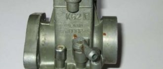
Carburetor K-62 disassembled.
Sometimes it happens that when starting or running a motorcycle, the carburetor sneezes. This happens due to problems in the ignition system. The first step is to replace the spark plug. If this does not help, then the ignition has failed. Usually the carburetor shoots during early ignition. Sneezing can also be caused by a mixture that is too lean. The combustion process of such a mixture is slow and when the piston opens the inlet window, the mixture shoots into the diffuser.
The main reason for a lean mixture is air leaks in the following places:
- from under the crankshaft oil seals;
- cylinder heads;
- at the junction of the carburetor flange and the cylinder pipe.
We try to find and eliminate the cause of air leaks using the elimination method. You should start with inspecting and adjusting the ignition system.