Reasons for repair
The most popular reason to repair a Ural motorcycle is considered to be insufficient dynamics of the motorcycle, smoke from the muffler, loss of traction at high speeds, and a decrease in maximum speed. Reasons that even inexperienced riders can note include increased fuel and oil consumption. If such problems appear, there is no need to disassemble the engine right away; first you should check the ignition, then the carburetor settings, measure the compression and check the valve adjustment, and after eliminating all other problems, you should get into the engine and repair the Ural motorcycle engine.
You might be interested in how to tune a Ural motorcycle. A detailed description of possible directions for tuning a bike!
More experienced owners may suspect a problem by the sound of the engine. Specific noise reveals a number of problems that are determined with high accuracy.
There are also a number of reasons to repair the engine that are not related to its breakdown. For example, the engine can be rebuilt during a long period of inactivity, during restoration, after a long mileage, and so on.
When assembling engine components and parts, pay attention to ensuring clearances and interference in the mating parts, adhering to the following values (see tables 10 and 11). The engine is assembled in the following order. Lubricate the threads of the plug with bakelite varnish, wrap it flush with the plane of the crankcase and mark it in two places. Install the MT801120 or MT801120-A retaining thrust ring so that the drain hole in the crankcase (4 mm in diameter) is in the ring slot. The outer race of the roller bearing is pressed into the crankcase until it stops, and the inner race is pressed onto the short shank of the crankshaft. Studs 216231-P8, 216236-P8 and MT801102 are screwed into the crankcase of the Dnepr K-650 and MT-9 motorcycle engines until they stop; for the MT-10-36 motorcycle engine, an additional stud 216462-P8 is screwed in. After installing the studs, pressing in the spacer sleeve 7201102, oil drain tube 7201103, its plug 7201104, bushings
7201106 lubricant pump drive gear and bushing
7201107 camshaft crankcase is carefully inspected. Cracks, under-pressing and distortions are not allowed. Bushing 7201106 is pressed into the crankcase with an interference fit of 0.01...0.02 mm, bushing 7201107 - with an interference fit of 0.02...0.01 mm (ensure by selecting bushings). In pressed bushings 7201106 and 7201107, the lubrication holes must coincide with the holes in the crankcase. After pressing in the bushing 7201106, it must be expanded to a diameter of 14+0019 mm. After pressing, the holes of the bushing 7201107 are checked with a pass gauge with a diameter of 22.02 mm.
In the engine crankcase, studs 009411-P29 or 009411-P8 (for Dnepr-12 motorcycles) must be screwed in all the way. The length of the protruding part of the right upper stud is no more than 41 mm, for the remaining studs - no more than 37 mm.
Assembling junction box covers. After pressing in the pins and races of the camshaft, the covers of the distribution boxes are carefully inspected; cracks and under-pressing are not allowed. The camshaft race with the oil seal must fit tightly into the cap groove.
On the engines of the Ural-3 M-66 and Ural M-67-36 motorcycles, a paper engine oil cleaner 660190, its spring 6601693 and a gasket 7205224-01 are installed in the distribution cover, which are tightened with a threaded plug 6601671. A bypass valve is also installed in the cover lubrication valve with pressure adjusting screw. After assembling the covers, check the lubrication lines for leaks with a pressure of at least 300 kPa. The valve should open at a pressure of 80±1 kPa.
Table 11.Nominal and permissible dimensions, tolerances and tensions of engine parts and clutch mechanisms of Dnepr motorcycles
in the main interfaces K-350, MT-9 and MT-10-36
| 1 | 2 | 3 | 4 | 5 | 6 | 7 | 8 |
| Valve guide MT801524 | 14+0.80 14+0.045 | 14,04 | Same | ,4+0.015 *-0,012 | 14,02 | — | 0,080 |
| Valve MT801523 | q-0.035° -0.060 | 7,9 | Valve guide MT801524 | 8+0,22 | 8,05 | 0,082 | — |
| Clutch pin | 19+0.080 lz+0.045 | 12,0 | Flywheel MT801223 | j 2+0.035 | 12,035 | — | 0,080 |
| Same | 19+0.080 IZ+0.045 | 12,0 | Drive intermediate clutch disc 7203117 | 12,5+0-07 | 13,0 | 0,525 | — |
| Clutch pin 7201225 | 19 + 0.080 lz+0.045 | 12,0 | Clutch drive pressure plate 7203121-A | 12,5 +0-07 | 12,6 | 0,525 | — |
| Reducing valve plunger MT801606 | 1 o—0.075 ll5—0.110 | 12,85 | Lubricant pump housing MT801607 | ! 3+0,07 | 13,08 | 0,180 | — |
| Lube pump housing | 2923+0.045 | 29,375 | Lube pump drive gear | ^9>z-0.04 | 29,1 | 0,200 | — |
| Clutch driven disc splines assy 7203113, 62030313, 7203114 | 4+0.05 | 4,2 | Splines for gearbox drive shafts 7204201, 6204201 | 4-0.04 *-0.P | 3,75 | 0,45 |
Note. The elasticity of the valve spring 7201419, compressed to a length of 37 mm, should be less than 380 N, the elasticity of the valve spring 6201420-01 (internal) should be less than 105 N when compressed to 30.5 mm, and the free length should be at least 39 mm . The elasticity of the valve spring 6201419-01 (external) when compressed to a length of 34 mm must be at least 160 N, and the length in the free state is 43 mm. The non-perpendicularity of the springs along their length should not exceed 1 mm.
Clutch pressure spring 7203115 is checked for compression elasticity up to a length of 21 mm, and the force must be at least 150 N.
The lubrication pump of the Dnepr K-650, MT-9 and MT-10-36 motorcycle engines should be assembled in this order: a pin is pressed into the pump body and the driven and driving gears are installed; put on the gasket and housing cover; install a bypass valve and intake pipe. Press the ball bearing 209 all the way into the ring of the front bearing housing of the engine, insert the assembled lubrication pump into the housing hole (with the shank of the drive gear), and into the holes of the bearing housing - studs or bolts with special washers installed on them and screw them in completely, bend them to the edge bolts edge washers. Install a key on the outgoing shank of the drive gear of the lubrication pump and then the pump drive gear, tighten the nut until it stops and use a cotter pin. The lubrication pump assembly with the front engine bearing housing is tested for the operation of the pressure reducing valve, tightness and pressure.
Selection of cylinders and pistons. Cylinders and pistons of normal or the same repair size are installed on engines. The gap between the piston and cylinder should be 0.07...0.09 mm for new pistons and cylinders and 0.08...0.10 mm for pistons and cylinders of repair sizes. To ensure selection, cylinders and pistons are sorted within each size into size groups, designated by size indices: cylinders - by bore diameter, pistons - by skirt diameter in a plane perpendicular to the axis of the pin. Dimensional indices are stamped on the piston bottom and on the cylinder flange; they correspond to the following sizes (Table 12).
Note. The numerator indicates the indices and dimensions adopted at the Kiev Motorcycle Plant, and the denominator indicates the Irbntsky Plant.
The repair dimensions of the cylinders and pistons are increased compared to normal: the first repair - by 0.2 mm, the second - by 0.5, the third - by 1.0 mm. To ensure the required clearance in the cylinder-piston interface within 0.08...0.10 mm, the above dimensions and indices are used. Based on the size of the holes for the piston pin, pistons, connecting rods (along the upper head with a bushing) and piston pins are sorted into size groups, indicated by color indices (Table 13).
Table 13.
Dimensions of pistons, connecting rods and piston pins, mm
The piston pins are selected so that their color index matches the index on the upper heads of the connecting rods. The finger should fit tightly into the hole in the upper head of the connecting rod under the pressure of the thumb. The clearance in the connection between the upper head of the connecting rod and the piston pin must correspond to that specified in Table 14.
Table 14.
Color indices of piston pins, connecting rod heads
and gaps in mating, mm
The color indices of the size groups of holes for the piston pin on the piston boss and on the connecting rod rod, corresponding to a given cylinder (left or right), in the assembled crank mechanism must match.
Before selection, the piston pin, connecting rod and piston are thoroughly wiped and blown with compressed air. The difference in the mass of pistons with selected piston rings and pins for one engine should be no more than 5 g. Piston rings are installed as normal or repair ones according to the sizes of the cylinders and pistons.
Assemble components and parts of the Dnepr K-650, MT-9 and MT-10-36 motorcycles in the following order. Press the inner race of roller bearing 420209 onto the short shank of the crankshaft until it stops. Disassembly of the bearing is not allowed. Install the assembled crankcase, insert the crankshaft into it upwards with a long shank, put on the front bearing housing assembled with the oil pump, align the mounting holes of the housing with the holes in the crankcase and press the housing until it stops. Then lock washers are placed on the mounting holes of the housing, the M8X18 bolts are “fastened” and all diametrically located bolts are gradually tightened. Lock the bolts with the bend of the lock washers.
Install the assembled crankcase with the mounting plane of the front cover down, install spacer and reflective washers on the crankshaft shank, place the assembled oil seal on a hole with a diameter of 85 mm and press it flush with the end of the crankcase hole. Measure the center-to-center distance between the crankshaft and the mounting holes for the camshaft with a size mark on the crankcase in hundredths of a millimeter plus or minus the nominal value to select a set of gears. It is allowed to replace one of the gears and then check the lateral clearance in the mesh. To set the proper clearance, gears are selected according to the center-to-center distance between the crankshaft and camshafts in the engine crankcase. For Dnepr motorcycles, the deviation of the center-to-center distance (in hundredths of a millimeter) is:
for crankcase assembly with crankshaft in a pair of gears
For Ural motorcycles, the crankcase group index is stamped at the factory on the top of the crankcase to the right of the generator, and the gear indexes are stamped on the end surface of the gears:
| Crankcase group | 0 | 1 | 2 | 3 | 4 | 5 | 55 |
| gear set | 13-18 | 12-17 | 11-16 | 10-15 | 9-14 | 8-12 | 6-10 |
According to the center-to-center distance, take a set of timing gears and press the driven gear onto the camshaft. Preliminarily lubricate the bearings with engine oil and press the camshaft into place, aligning the housing holes with the threaded holes in the crankcase, “fit” the screws and then tighten them.
Press the timing drive gear onto the front journal of the crankshaft, aligning the keyway with the key and the timing marks. The lateral gap between the gear teeth should be 0.03...0.08 mm, while fluctuations in the gap value in the same pair of gears should be no more than 0.05 mm.
Install the gasket on the drive gear. Place the centrifuge body on the front journal of the crankshaft, aligning the key groove with the key, and check the coincidence of the diameter hole
5.5 mm meter in the centrifuge body with a lubrication line hole in the crankshaft with a pin 4 mm in diameter and 80 mm long. Place the sealing ring in the annular groove of the centrifuge body. Place the centrifuge screen on the recess of the housing, aligning the protrusion in the screen with a hole with a diameter of 5.5 mm in the housing. Install the centrifuge cover on the front journal of the crankshaft, aligning the groove with the key.
Put two washers, a washer gasket and an O-ring on the M.10-22 bolt. Screw the bolt into the M10 threaded hole
the front journal of the crankshaft, aligning the protrusion of the washer with the depression in the centrifuge cover. After tightening the bolt, lock it with the bend of the lock washer onto the edge of the head.
Lubricate the breather with oil and install it on the camshaft gear, aligning the hole in the breather with the pin in the gear. Lubricate the gasket on both sides with Lito-lom-24 and place it on the crankcase connector plane.
Install a special mandrel on the camshaft shank to protect the oil seal from damage (Fig. 45) and place the junction box cover on the crankcase: tighten the M6X40 and M6X55 bolts, having previously put washers with a diameter of 6 mm on them. Screw the intake tube into the lubrication pump housing and secure it with a nut. Install the oil receiver assembly, securing it with M6X16 bolts, after putting washers with a diameter of 6 mm on them. Take the pan assembly, apply a gasket and attach it with M6X16 bolts and washers 252143-P2 to the crankcase. Wrap the filler plug assembly into the crankcase, placing a gasket under it. Install into the threaded holes of the crankcase: M8X40 studs for fastening the gearbox, M8X14 studs for fastening the generator stop, M8X14 studs for attaching to the motorcycle frame and screw them in sequentially until they stop.
Install the generator clamp assembly, attach it with M8X18 bolts to the crankcase, having previously put on washers with a diameter of 8 mm. Place the generator sealing gasket, install the assembled generator and its stop.
Place pistons (without fingers) with rings, assembled according to color indices and weight, into an electric furnace or water bath and heat up to 8O...1OO°C. Before assembly, the upper connecting rod heads and fingers are wiped dry with napkins. Place the finger on the mandrel, inserting a guide cone into the hole of the finger on the other side; lubricate the finger with engine oil; align the hole in the piston with the hole in the upper head of the connecting rod and press the piston pin into place by hand (see Fig. 16). Use gloves to maintain the hot piston. The piston pin must be installed quickly, as the piston cools down and the pin can “get caught”. Pressing the finger in with blows is unacceptable; If the finger gets stuck, it must be pressed out and the operation repeated. The arrows on the piston crown should point towards the lubrication pump. Install the retaining rings with the bent end outward. The right and left pistons, complete with pins and rings, must be of the same weight group.
The piston ring locks are moved apart at an angle of 120° relative to each other. Insert the oiled drain tube gaskets into the crankcase holes with a diameter of 15 mm on the cylinder mounting plane. Take the cylinder, lubricate its mirror with engine oil, put a lubricating gasket on the neck, lubricate the piston and its pin with oil. The piston rings are clamped with a tape or special clamp (see Fig. 18), then the cylinder is put on the piston and on the crankcase studs and the nuts are screwed in completely. Similar work is done with the second cylinder.
A gasket is placed on the upper flange of the cylinder. The gasket that has ruptures and burnouts is replaced with a new factory one or hand-cut from reinforced asbestos. A gasket cannot be made from unreinforced asbestos, as it is quickly damaged during operation. A gasket made from Klingerite is more difficult to make and is less reliable than one made from reinforced asbestos. In the absence of reinforced asbestos, you can cut out a gasket from sheet copper with a thickness of 0.3...0.8 mm, then it is heated red-hot and quickly dipped in cold water to make it soft.
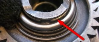
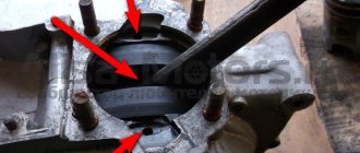
To install the right cylinder head, pushers are installed in the crankcase sockets, having previously lubricated them with oil. Gap
between the valve and the guide sleeve there should be 0.035... 0.083 mm. Figure 46 shows how to measure the side clearance between the valve stem and bushing. After this, the rod assemblies are inserted into the housings and the sealing caps are put on. Install the assembled head on the studs, aligning the rod casings with the sealing caps and the drain tube with the hole in the crankcase. After placing the washers, secure the cylinder head with special nuts. The nuts are gradually tightened crosswise so that
so that the head is installed on the end of the cylinder without distortion. The left cylinder heads are installed in the same way.
Lubricate the valve springs, rocker arm axes and rod tips of the right and left cylinder heads with oil, install the cylinder head cover gaskets on the pins and secure the covers by tightening the bolts and washers.
Screw the carburetor mounting studs into the right and left cylinder heads until they stop, put the carburetor gaskets on the studs, install the right and left carburetors; put washers on the studs and tighten the nuts.
Install the flywheel with the clutch pins assembly onto the cone of the rear journal of the crankshaft, and put on the lock washer of the flywheel bolt. Tighten the flywheel mounting bolt and secure it by bending the lock washer onto the face of the head.
Install clutch pressure springs of the same color. Clutch discs are placed on the springs sequentially: driving pressure, driven assembly, intermediate, driven assembly with oil deflector 7203113 and driving thrust. The disks are connected with a splined mandrel, a special device is applied and the springs are gradually compressed, while aligning the 12.5 mm diameter holes of the pressure and intermediate disks with the flywheel pins. Align the holes of the drive thrust disk with the threaded holes of the pins, install the screws and tighten, unpunch the screws on both sides of the slot. It is not allowed to place cores closer than 3 mm from the edge of the disk. If the slot gets closer than 3 mm from the edge of the disk, the cores are placed on one side of the slot, but no more than three screws. Screw heads must not protrude
above the plane of the disk. Discs must be clean from oil and dirt.
The engines of the Ural and Dnepr-12 motorcycles are finally assembled in the following order. Bearing 207 is pressed all the way into the front bearing housing preheated to 100...120 °C. Then the housing with the bearing is pressed into the engine crankcase and centered with bolts in relation to the mounting holes. The housing should be pressed in carefully, without
allowing chips to be removed from the crankcase body. When installing the crank mechanism into the crankcase, the slot for the timing gear key on the front axle should be at the top. The device is used to pull the front end of the crank mechanism into the front bearing (Fig. 47). Press the oil seal and ball bearing into the rear bearing housing, placing a spacer and baffle (for oil) washers between them.
Lubricate the rear plane of the crankcase with sealing varnish (bakelite varnish or “Sealant” varnish), apply a lubricated gasket to the rear bearing housing and press it into the crankcase, centering it with bolts in relation to the crankcase mounting holes. Secure the rear bearing housing with bolts, tightening them crosswise. Seal the bolts securing the front and rear bearing housings with round wire. Insert the segment key into the rear end of the crankshaft.
Press the timing drive gear onto the front journal of the crankshaft and put on the washer, aligning its slot with the protruding end of the key. Install the lock washer and tighten the bolt until it stops. Lock the bolt with a bend to the edge of the lock washer. The gap between the inner race of the rear ball bearing and the thrust collar of the rear axle is allowed for new parts of 0.66...1.9 mm, for repairs - 0.66...2.3 mm. The crankshaft mounted in the crankcase should rotate easily by hand and not jam.
Before installing the camshaft, its rear journal and bearing are lubricated with engine oil. The shaft can be pressed in with light blows of a hammer on a mandrel installed on the end of the shaft and resting against the hub of the driven distribution gear. The lateral clearance between the wheel teeth should be 0.01...0.2 mm. Fluctuation of the gap is allowed no more than 0.05 mm. The driven gear is pressed onto the camshaft until it touches the collar without distortion. The runout of the end of the gear wheel when the shaft rotates on the support journals should not be more than 0.08 mm.
Bearing 205 with the camshaft is pressed into the crankcase until it stops and secured with screws through the flange. The gasket of the junction box cover is lubricated on both sides with sealing varnish. When installing the box, a tip is placed on the toe of the camshaft to protect the edge of the oil seal from curling. The breather with the cover hole should have a gap of 0.075...0.4 mm. When installing the lubrication pump, it is necessary to ensure that the gasket does not block the lubrication line, and that the pump housing fits snugly against the supporting surface and that the pump drive rod fits into the square hole of the gear. The pump is secured and pinned with wire. The lubricant cleaner must be clean and have a working mesh before installation. The gear plug of the lubrication pump drive is tightened until it stops, but it should not pinch the gear. During installation, the tray lining is lubricated on both sides with sealing varnish. The planes of the pan and crankcase must be clean and free of nicks and burrs. Spring washers are placed under the bolts.
They check the conformity of the dimensional and color indices on the pistons, cylinders, pins, connecting rods, applied when selecting these parts, and that the sets of pistons with pins and rings belong to the same weight category. The gap between the guides and pushers is 0.016...0.2 mm. The pushers should slide easily in their guides without distortion or jamming. Before installing the cylinder head, the cylinder mirror is wiped and lubricated with engine oil. The gap between the valve stem and the pusher adjusting screw on a cold Dnepr engine is set to 0.1 ± 0.01 at the exhaust, 0.07 ± 0.01 mm at the intake, and 0.05 mm for Ural motorcycles; the adjusting screws must not have clogged edges and must be locked.
The gaskets of cylinders, covers, and valve boxes must be intact. Cylinder nuts and cover bolts
valve boxes are tightened evenly. The flywheel with clutch pins is installed tightly, without rolling, at the end of the rear axle. The gap between the flywheel and the rear housing of the engine crankcase must be such that the flywheel does not touch the bolts when turning the crankshaft. The flywheel mounting bolt is secured with a lock washer.
Install the generator in the crankcase housing so that the generator gear is located to the right of the axis of its housing, when viewed from the side opposite the drive. The gap between the gears of the generator and the camshaft is adjusted within 0.01...0.2 mm by rotating the generator housing in the crankcase seat. Fluctuation of the gap is allowed no more than 0.05 mm. After adjustment, the generator is securely secured by tightening the clamp bolt. After securing the generator, the distribution gears should turn smoothly, without jamming. The G-424 generator, installed on the engines of the Dnepr MT-10-36 and Ural M-67-36 motorcycles, is secured with its flange to the engine crankcase with two studs. The gap in the engagement of the generator drive gear is also adjusted by turning the housing. To make adjustments, start the engine, loosen the generator mounting nuts, turning the housing in one direction or another, find the optimal engagement of the gear wheels, at which the generator operates silently, and secure it in this position.
The drive pressure and intermediate clutch discs must slide freely on the flywheel pins without jamming or distortion. Clutch pressure springs are supplied with only one marked group (painted in the same color). The thickness of the disc set should be 18.8…20.4 mm and vary within one clutch by no more than 0.5 mm (this is ensured by the selection of parts).
The screws for fastening the drive thrust clutch are tightened and drilled into a slot on both sides. The screw should not protrude beyond the plane of the disk. When installing a screw slot closer than 3 mm to the edge of the disk, the slot is cored on one side, but on no more than three screws.
The repaired engine must be run in to break in the main parts, adjusted and tested to assess the quality of the repair and compliance with specifications.
Repaired units can be run in on a motorcycle frame. The motorcycle with the repaired unit is placed on a stand, the engine is started, which should idle at a crankshaft speed of 60...700 min"1 for 5...8 minutes, then turn on fourth gear and run in for another 8...10 minutes at a speed of 1500...2000 min-1. Then all gears are turned on one by one for 10...15 minutes with a rotation speed of 2000...2500 min"1. After break-in, drain the oil and fill in new oil. Now you can start running in while maintaining maximum speeds: in first gear - 15 km/h, in second - 15...25, in third - 25...40, in fourth 40...50 km/h. Overheating is not allowed in all operating modes. The gearbox and main gear are run in similarly according to the following regime: in first gear - for 10...12 minutes, with a rotation speed of 1500 min-1, in second - for 8-10 minutes with a rotation speed of 2000 min-1, in third - with rotation speed 2000…2500 rpm for 5…8 min. After that, drain the oil and fill the unit with new oil and then run it on the go according to the specified regime.
Choosing a case that suits your needs
Having set the goal of tuning a Ural motorcycle with your own hands, it is important to understand that there are modifications that are relatively painless and do not require documentary evidence to register the vehicle and undergo a technical inspection.
And there are changes that, in order not to conflict with the law, must be agreed upon with the manufacturer or other regulatory authorities. Based on this, tuning for a Ural motorcycle should be divided into two categories:
We will consider each of these categories separately.
Assembly. The first day.
Greetings to all readers of my bortovik and, of course, just random passers-by...
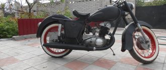
Today I want to share my experience of assembling a Ural , because as I wrote earlier, the parts are painted, dried overnight and in the morning I go to the garage. I immediately took tapered bearings bought on Aliexpress, installed them on the lower crossmember of the front fork, filled them with grease, tightened them with a nut and put on the fork guards as they are installed before installing the crowbars. I also installed the rear swingarm and center stand.
Then the assembly went as if in a dream - before I had time to come to my senses, a fork, a rear fender, a steering wheel, a wiring braid appeared... and when I remembered that I needed to take a photo for MOTO2 , I decided to just put on the tank and seat for verification so that it already looked like something.
Then there was a hitch. All my wheels (and there are about 20 of them) are now in a state of either restoration or new (which are still a pity and will be installed in the process of completion), but the truth was one wheel assembled with a “daisy” hub , which for some reason I don’t like much, and therefore I had to go home for the second and third, because... At home there is a pair of so-called restoration wheels that I purchased from a friend in Irbit when I was passing through there. I didn’t prepare the wheels in advance because... I assembled the motorcycle for one time (just go and register it with the traffic police ) and was sure that a friend would give me a spare wheel from his motorcycle to travel 30 km. But imagine my surprise when he refused me... I honestly didn’t even think about it. It will be a lesson to me. I took two rims from home, put tires on them (it’s good that I have a large selection of them) and put the motorcycle on MY wheels.
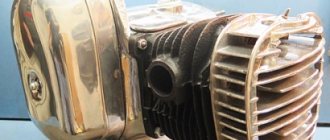
Now that the spendthrift has received all the support points, you can roll it out onto the street and continue to work without being constrained in space. Installed the engine. I also have several of them, probably 6 of them, but I have not yet had time to completely disassemble this particular motorcycle for complete repairs and modifications, but only took off the heads, generator and ignition to see at least the approximate condition, because. Let me remind you that the motorcycle was dead and had not started for several years. I didn’t take the gearbox from this motorcycle, but from another one previously purchased for free with only 4400 km .
I installed a rear axle with a cardan, also from a donor, with a mileage of 4400 km , and began to do what I love - wiring
Wiring is a complex, but interesting business. I immediately installed a charging regulator relay from the car, since on standard relays either the generators burn or the batteries boil... I temporarily left the charging control light unused, I’ll fix it later, but on this relay there is no reason to worry and, in extreme cases, there are two on the relay itself control lamps (one shows that the voltage is suitable and the second that there is a charge). Then I started working on turn signals. For right turns you need to throw an additional wire, so I left this work for the next day, and today we connect the left ones, tidy, brake light and headlight. While I was working on the turn signals and tidying up, it was getting dark outside—it was autumn, the days were short (although the weather didn’t tell us that it was the end of October).
After dark it became inconvenient to work on the street and we again moved to the garage where we continued to work on electrical work. I connected the neutral control lamp and connected the headlight.
The last one for today is a brake light with side lights.
October 29, 2019 turned out to be such a productive day . Literally in one day the motorcycle turned from a bunch of parts into one whole, of course there is still a lot of work ahead, but that’s for another post!! All the best!! And finally the result of today...
If anyone needs more information about the relay, for example, or about the wiring, then you can write in the comments what is interesting, I will make a separate post with a more detailed explanation...
Motor defective
The process of disassembling the motor is quite complicated, but what is more important is that the existing gaps “go away.” Thus, if you disassemble the motor and then reassemble it without repair, extraneous noise is likely to appear due to the increase in gaps. Therefore, experienced mechanics advise, first of all, to assess the condition of the motor without disassembling the main elements, or to carry out a partial disassembly, then carry out troubleshooting and, based on its results, decide whether to make repairs or not. A malfunction can be determined “by ear” if:
Reason: wear of the piston pin and the appearance of an excessively large gap between the pin and the bushing. Solution: first of all, you can set the ignition later, in some cases this either completely eliminates the noise, or it becomes insignificant, which allows you to use the motorcycle for some time. If this does not help, then the old pins are replaced with new ones, as well as the connecting rod bushings with their subsequent development.
Reason: the appearance of a gap between the pin and the piston boss. Solution: replace the pin + piston set with new ones of the same group.
Reason: clearance between piston and cylinder. Solution: selecting a new piston of the next repair size and boring the cylinder for a new piston group.
Reason: This sound may indicate an increase in the gap between the lower end of the connecting rod and the crankshaft crank pin.
By the behavior of the motorcycle you can find out about the following problems:
Cause: worn piston rings. Solution: complete replacement of the piston rings, and if there is damage to the cylinder plane, boring it, with subsequent repairs.
Owners of the Ural motorcycle most often encounter similar problems. As you can see, most problems are diagnosed by craftsmen “by ear”, and despite all the primitiveness, the result turns out to be very accurate. Assuming there is a problem with the motor, you should stock up on a set of necessary pullers, keys and repair parts, and only then begin disassembly.
MY MOTORCYCLE
Everything has been purchased, selected, bored, turned and polished, all that remains is to assemble the parts together. But, as usual, this is easier said than done, especially when it comes to non-standard solutions.
Installing a crankshaft from a modern Ural into an ancient, post-war engine is not an easy task: despite the similar dimensions, problems can arise even with penetration into the inside of the crankcase. The Tru Motor workshop knows all the pitfalls, so they began sawing the crankcase long before assembly. How?
Let us remind you that in order to install the crankshaft of a modern Ural into the M-72 crankcase, its journal was ground down to fit an old-style bearing. And we bought a new back cover - with a bearing and oil seal. But due to its larger size, the crankshaft... does not physically fit into the crankcase. Therefore, Vasily took the original rear cover gasket of the new model (photo 1), marked the outline along it with a marker and made two cuts with a milling cutter, thanks to which he was able to insert the shaft into the motor (photo 2). Now the shaft can be inserted into the crankcase by first pressing the main bearing onto the pre-machined front journal (photo 3). But only in one way - with both connecting rods forward, carefully sticking them out through the side holes of the crankcase, at the same time turning the shaft along the longitudinal axis of the crankcase (photo 4).
We used main bearings marked “C3”, with increased lateral clearance. In a hot air motor, such bearings last longer than conventional ones. On modern engines IMZ uses exactly these.
The rear crankcase cover from the new Ural is much thicker and heavier than the original one, but the bolt pattern is almost the same. Why almost? Its mounting holes are designed for M8 bolts, and in our crankcase there are holes with M6 threads, so Vasily modified them too, drilled and cut new threads (photo 5).
We attach several bots securing the back cover without tightening them. Now the task of the cover is to fix the crankshaft in order to protect it from distortion when retracted into the front support. The crankshaft with the pressed bearing must be pulled with a puller into the front support attached to the crankcase (photos 6 and 7). It needs to be modified in advance - cut off the inner flange, which previously kept the bearing from moving inside the crankcase. On modern engines, the crankshaft is fixed axially through the rear bearing, and not the front, as it was before. Therefore, it is necessary to give the bearing freedom in the front support.
Now we remove the back cover, place the gasket (it must be lubricated with sealant and allowed to dry for 10 minutes), attach the cover again with two or three bolts and press it evenly into the crankcase with light blows of a rubber mallet (photo 8). Now you can tighten the bolts of the rear crankcase cover onto the thread lock (tighten evenly “every three” to eliminate the risk of distortion). We press the bearing with a mandrel through the inner race, then install the retaining rings, paying special attention to their uniform entry into the grooves on the elbow and crankcase cover (photo 9). During the process of pressing the shaft into the bearings, it may rest against the front or rear wall of the crankcase, making a rustling noise when touched; it can be centered with light blows of a mallet.
The camshaft bushing in our crankcase is extremely worn out, so even the new shaft is hanging out in it. Pressing out the old one by tapping it with a hammer, for example through a head with an extension (photo 10), is not difficult, just like pressing in a new one, but there are a couple of nuances here.
First, bushing sizes may vary slightly. However, choosing the right one is not difficult: we put it on the camshaft and, holding the side hole with a finger, sharply pull it off. Did you hear a quiet sound reminiscent of a bottle of foam opening or feel a vacuum being created? This means the bushing fits (photo 11).
The second nuance is the side hole, which must completely coincide with the hole on the crankcase. Through it, oil is supplied to the distributor. Combining them is quite simple: to do this, you need to mark with a marker the location of the hole on the crankcase and the bushing (photo 12), and when pressing, simply align them (photo 13). You can press in a new bushing in the same way as the old one was knocked out, but it is better, if you have an old, worn camshaft, to press in the bushing by tapping it.
Now it’s the turn of the timing belt: we close the crankshaft bearing with a cover with an oil supply spout, aligning the holes in the line (photo 14), and install the key, after which we proceed to the most difficult operation - selecting gears. There is a separate kit for each of the eight groups of crankcases, differing in the distance between the crankshaft and camshaft. Knowing it, it is not difficult to select the necessary kit, but in our case the numbers on the crankcase are erased, so you will have to look for a suitable option “by scientific poking.”
We press the small gear onto the crankshaft, preheating it to approximately 160 °C (photo 15). You need to be more careful with the large camshaft gear, because before pressing it in, you must first press in the bearing (photo 16) and put on its cover, which is attached with two screws to the crankcase (photo 17). Correctly selected gears should have a gap between the teeth of 0.03-0.08 mm (measured with a feeler gauge or dial indicator). Excessive play can lead to noise and “floating” ignition, and too close contact of the teeth leads to increased wear, as well as wear on the shaft bearings. Gears are ground in pairs at the factory, so it is advisable to select them in pairs. To remove the small gear, you will need a puller. And in order to start its paws, it is first moved with two mountings, resting them on the crankcase.
Having selected the gears and aligned the marks (photo 18), tighten the screws of the camshaft bearing cover with an impact screwdriver (photo 19), install the spacer and lock washers on the crankshaft gear and tighten it with a new bolt and fix it (photo 20). The gear bolt of the original shaft, like the shaft itself, has a thread with a fine pitch, and the new one has a coarse pitch (photo 21).
The original oil pump went to the garage shelf: despite its proper operation, its performance cannot be compared with the similar pump of the new Ural, which installs practically without modifications. The main thing is that the square profile of the pump drive rod is machined to a round one (photo 22), otherwise the rod will touch the massive cheek of the new crankshaft. The pump is installed with a gasket (photo 23), and the mesh, which catches pieces of pistons and fragments of rings, is secured with wire passed through the holes in the screws (photo 24).
Having finished with the pump, we install the pan through the rubber-cork gasket, placing the bolts on the thread sealant (photo 25). We install the oil pump drive gear, having previously lubricated it with oil (photo 26), and tighten the cover. It is important not to overdo it with the tightening torque, because the lid is made of soft and brittle metal.
Now that the oil pump and pan are in place, we return to the timing mechanism. We leave the crankcase ventilation breather spool as original, but before installation we modify it: the round hole for the driver on the timing gear needs to be expanded - just like on modern Urals (photo 27). With such a hole, it will be able to be properly centered in the hole of the cover (photo 28), which we install after first fitting the “Chinese” gasket.
The thread in the hole for the stud securing the front ignition cover was torn off, so we installed a longer stud and secured it with nuts on both sides and sealed it for reliability. But they decided not to follow the latest fashion; they preferred original, slotted screws to the fancy hexagons; they are more canonical. The original screws were left in the camshaft oil seal race, having first replaced it with a new one (photo 29).
What's next? Lightening and balancing the flywheel, assembling the cylinder-piston group, clutch and electrics, which we will talk about in the next issues.
To be continued…
Issue: MOTO Magazine - July 2015
Author: Dmitry FEDOTOV, photo by the author
A little history
The products of the Irbit Motorcycle Plant are well known not only in our country. Various models, whose design originates from the pre-war BMW R71, have retained their parental genes for seventy years. True, the prefix “Ural” appeared in their name a little later. Since 1961, it has been assigned to the following modifications:
Next, it was decided to limit ourselves to the name Ural, removing the additional digital index and leaving only the factory designation.
And this is not counting special versions and limited editions. But in the process of tuning a motorcycle, any of the listed modifications have a lot in common. Despite the changes in the name, all models are similar in design and have similar technical characteristics.
avtorep.ru
A Ural motorcycle has been in the garage since 1998. The motorcycle is separate, the engine is separate, the gearbox is in a completely different corner. I spent my entire childhood on this motorcycle, after buying a car, they forgot about it. And so I decided to restore it...
First, it was decided to deal with the engine, since, according to the owner, the crankshaft was knocking. Therefore, we immediately began disassembling the engine.
Removing the cylinders
I removed the heads, checked the piston clearances in the cylinders, everything was fine, only the right cylinder had a rusty emulsion - apparently moisture had gotten in. But fortunately the cylinder mirror was not damaged.
I checked the gaps on the fingers - everything is within normal limits. I pressed out the fingers, marked where the right and left parts of the cylinders were and put them aside.
Removing the clutch
Then I started disassembling the clutch to remove the flywheel. A simple screwdriver and hammer blows were not enough to unscrew the screws the first time. There is no point in buying an impact screwdriver just for one use. I turned on my ingenuity. And so he pressed the engine from the frontal side into the opening of the garage door, and pressed the screwdriver to the bolt with the help of a block and a jack, and with a gas wrench tore off the metal beads. And then everything opened without problems. I removed the clutch and started disassembling the frontal part, since I didn’t have a 36mm socket wrench on hand to unscrew the flywheel.
Removing the timing belt
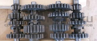
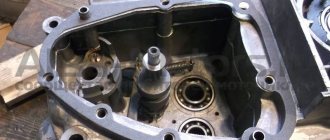
In the frontal part, everything is disassembled simply, the cover is unscrewed, the ignition is removed, the ignition coil is removed, then the windshield is unscrewed. I unscrewed the two bolts that hold the camshaft and placed two mounting brackets under the camshaft gear using rags. And he pulled out the camshaft and gear. Upon inspection, no wear was found in the timing gears. The bearing is also in excellent condition. I secured the pushers with electrical tape to prevent them from falling into the crankcase and getting tangled.
Then I went to a friend and took from him a three-legged puller and a 36mm socket wrench. I unscrewed the bolts that hold the crankshaft main bearing in place at the front. And as in the video, I decided to grab the pressure washer with the puller, since the puller’s legs do not fit under the gear. The result is that the gear is removed, the pressure washer is bent and torn. Conclusion, it was necessary to tie steel wire around the gear and pull it. It will be a lesson for the future.
Removing the flywheel
After disassembling the timing belt, I started working on the flywheel. For the flywheel, you need a wrench so that the working edge is straight away, and not, like most heads, slightly recessed, since the flywheel bolt has thin edges. To fix the flywheel, I used a 12mm wrench and inserted one end into the clutch bolt and the other into the stud securing the box to the engine. I’ll say right away that it’s better not to do this, since I bent the pin. It’s better to take a 19-size open-end wrench, insert one end into the hole in the flywheel, and the other into the rod that you need to insert the lugs for attaching the engine to the frame. This is what was done when assembling the flywheel.
When I unscrewed the flywheel bolt, I pulled off the flywheel using a puller. Next, unscrewing the 9 bolts that hold the rear main bearing cover in place, I used the same puller to remove the cover itself. And now the reason for the knocking crankshaft was discovered - the main bearing separator had crumbled.
Removing the crankshaft
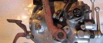
To remove the crankshaft, you need to remove the oil pump. To do this, I drained the oil and unscrewed the pan. I unscrewed the top cover of the oil pump and took out the gear. From the bottom of the pan, I removed the pump mesh and unscrewed it and removed it along with the rod, which will not allow the crankshaft to be removed.
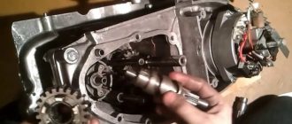
Using a wooden mandrel and a hammer, I removed the front main bearing. To do this, the engine was placed on the floor with its back side. I placed a wooden mandrel against the front shank of the crankshaft and, using gentle and gentle blows of a hammer on the mandrel, knocked out the crankshaft from the front main bearing.
Next, to pull the crankshaft out of the engine, I took it by two connecting rods and put it in the position in which the connecting rods are at bottom dead center, then after twisting it a little inside, I pulled it out through the rear cover, and put it in place in the reverse order.
I cleaned the front crankshaft oil catcher of slag with steel wire, and I removed almost the entire main bearing cage from the rear oil catcher. The crankshaft itself had no wear above normal. I washed the inside of the engine with solarium to remove any chips that had formed during operation.
Ural motorcycle engine assembly
I found 207 bearings and assembly began. The first thing I did was put the crankshaft inside, I can’t explain exactly how it gets there, well, a few manipulations and it’s there. It didn’t work the first time, because I didn’t move the connecting rods correctly, and the right connecting rod ended up in the left window, and the left one in the right, so I had to pull it out again and put it back in place.
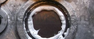
Then, heating the main bearings with a gas burner, I installed them in place. They finally fall into place when you install the pressure washer on the front (I replaced it with a new one, I did not restore the old one). And on the back is the back cover. To do this, they are first seated with long bolts, and then the original bolts are put in their place. I installed the back cover with sealant so that I wouldn’t have to worry about cutting out a new gasket.
When assembling the back cover, while tightening one of the bolts, it broke off. I had to drill a hole in the broken bolt. I tried to unscrew it first, but it didn't work, so I drilled the hole larger and cut a new thread. In the future, these bolts need to be replaced with new ones, as they tend to break off when tightened.
After that, I installed the timing gears, don’t forget about the lock washers. I did not use thread locker, but pinned the bolts with wire. Since this is my first time assembling and disassembling a Ural engine, I suddenly have to disassemble it again.
The timing gears are placed strictly according to the mark. Next, the breather is installed, the windshield is on top, and I bolt it on. I install the ignition in place, approximately according to the marks where it was. After that, I installed the rear main bearing seal. I installed it at the last moment, only after everything was assembled and checked. In order not to disassemble it again, rubber products do not like this.
I took the oil seal from a repair kit purchased back in the “dashing 90s”, it’s good that it was preserved.
Reinstalled the oil pump. Installed the flywheel and tightened it. Reassembled the clutch. Since there were no long bolts or studs on hand, in order to install the clutch as per the book, I had to press on the discs with my knee and tighten them with the original bolts “cross to cross”. This suggests once again that Soviet equipment can be repaired in the field.
Dismantling the Ural motorcycle engine
Repair of a Ural motorcycle should be carried out in stages. The first step is to prepare your garage and the engine itself. All dirt and oil must be washed off the engine so that they do not get inside. Laying a film on the floor will help protect the garage floor, because it is easier to throw away a piece of cellophane than to remove the remaining grease from the garage floor. Disassembly process:
Following this diagram, you will be able to get to the main parts of the engine in order to conduct a full diagnostic of the gaps and, if necessary, replace the parts with new ones. It is worth noting that if a part has a gap close to wear, then it is better to replace it, since most new spare parts lead to increased load on the entire engine while it is running in. Such increased pressure on old components can lead to their wear, which means the appearance of noise.
We recommend carrying out comprehensive repairs before the start of the season. This approach will allow you to get rid of all problems with mismatched gaps and skate several seasons without worries. Otherwise, the motorcycle engine may break down at the height of the season and make it impossible to move on two wheels for a long time.
Ural engine assembly
Engine YaMZ-530
Before assembling the engine of a Ural car, lubricate with sealing non-drying paste the rear end of the cylinder block, the front end of the flywheel housing (including the starter mounting flange), the joint planes of the upper and lower parts of the flywheel housing, the threads of the bolts securing the lower part of the flywheel housing, as well as the starter flange.
All parts and assemblies received for assembly must be thoroughly washed and checked. The mating parts must be selected and adjusted. The following are not allowed for installation on the engine:
- used cotter pins, cotter wire and locking plates;
- spring washers that have lost their elasticity; damaged gaskets;
- parts with more than two clogged or torn threads, bolts and studs with elongated threads, bolts and nuts with worn edges.
Installation of the camshaft of a Ural car. Before installation, lubricate the cams and camshaft bearings with engine oil and check the alignment of the oil channels. Install the camshaft with gear, flange with spacer ring and centrifugal crankshaft speed limiter sensor drive assembly into the cylinder block. Install the shaft carefully so as not to damage the surfaces of the bushings, cams and shaft support journals. Install the camshaft and crankshaft gears by aligning the marks. After stopping them, measure the gap in the engagement. Lubricate the timing gears, place the oil deflector on the end of the crankshaft, install the timing gear cover assembled with the oil seal and gasket, and secure the cover with bolts. Install the crankshaft speed limiter sensor, press on the pulley, and tighten the ratchet with the lock washer.
Installing the oil sump . Install and bolt the partition and oil receiver assembly. Glue the gasket to the oil crankcase, lubricate the split plane of the block and the gasket with VTU MHP 3336-52 sealing paste, install the crankcase on the engine and secure it with bolts, tightening them sequentially from the middle to the edges. Assemble and install the cylinder head in the following sequence:
- insert the valves into the bushings according to the marks made and assemble them with the springs. Install a valve rotation mechanism on the exhaust valves, and oil deflector rubber cuffs on the intake valves. Make sure that the projections of the crackers fit into the annular groove of the valve stem;
- Place the cylinder head gaskets with the grooved surface facing up, lubricating them with non-drying sealing paste around the holes in the inner row;
- install the cylinder heads and pushers into the cylinder block sockets, then insert the rods, connect the ends of the rods with the rocker arms and secure the rocker arm axes to the cylinder heads;
- insert the remaining bolts, connecting the spark plug guards, tighten the cylinder head bolts, observing the order and tightening torque of the bolts.
Installation of inlet and outlet pipelines, ignition distributor drive and accessories . Before installing the pipelines, clean the mating surfaces from dirt, insert the fuel pump drive rod into the cylinder block, and install the intake pipe gaskets. Install the inlet pipe. In this case, tighten the nuts crosswise with a tightening torque of 1.5-2.0 kgf-m. Install the exhaust pipe, distributor drive, water pump, compressor, fuel pump, carburetor, power steering pump, drive belts, centrifuge, starter and alternator. Screw in the spark plugs, connect the pipelines to the units (water, fuel, etc.), screw in the oil pressure and water temperature sensors, install the cylinder head covers. Connect the wires and install the ignition coil and ignition distributor. Adjust the gaps in the gas distribution mechanism and install the ignition.