contents .. 11 12 ..
REPLACEMENT OF PISTON RINGS, PISTONS, PISTON PIN AND CYLINDERS OF MOTORCYCLES “DNEPR” AND “URAL”
Piston rings and pistons are replaced in case of the following defects: a decrease in compression in the engine to a value of less than 450 kPa, which is determined by a compression meter when the valves are closed regardless of the tightness; smoky release of gases; intense carbon formation on the cylinder head and piston, independent of carburetor adjustment.
By replacing the piston rings, piston with piston pin and cylinder, decreased compression is restored, normal fuel consumption is restored, and some extraneous knocks are eliminated.
Piston rings are replaced after the motorcycle has run approximately 10...12 thousand km. Signs of ring wear are engine oil consumption of more than 0.15 liters per 100 km and an increase in the gap in the lock of more than 1.2 mm.
Before installing new rings, they are adjusted along the piston groove manually, sawed with a personal file (Fig. 14) and treated with emery cloth, then the clearance in the lock is checked. The gap is measured at the ring inserted into the cylinder without distortion. It is convenient to align the location of the ring in the cylinder with a piston inserted after the ring. For compression rings, the gap should be 0.04...0.08 mm (only for new ones), for oil scraper rings - 0.025...0.06 mm.
If it is necessary to replace only the upper compression rings, then non-chrome plated rings are installed, since chrome plated ones wear in slowly. To check whether the height of the ring matches the width of the piston groove, the ring is inserted with its outer side into the groove and rolled along it. The gap in the piston grooves should be 0.025...0.08 mm.
A correctly fitted ring placed on the piston is recessed into the groove under the influence of its own weight. If the fit is too tight, the ring will not move enough and can therefore easily jam and burn. Therefore, it is necessary to maintain these gaps in accordance with the factory operating instructions for this motorcycle model.
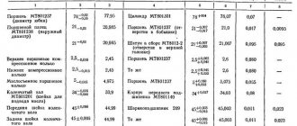
The correspondence of the thickness of the ring to the depth of the piston groove is checked as follows: the outer side of the ring is inserted into the piston groove, and a ruler is applied to the piston parallel to its longitudinal axis with its edge so that the section of the ring immersed in the groove is between the bottom of the groove and the edge of the ruler. The ring corresponding to the depth of the groove is recessed into it by 0.4...0.5 mm and moves freely. If the ring is not recessed in the groove, then when the piston expands and carbon deposits form under the ring, the bottom of the groove will put more pressure on the ring and, therefore, the piston may jam in the cylinder. The piston and piston pins are replaced after approximately 18...20 thousand km of the motorcycle. The side walls of the piston ring grooves, the piston pin holes and the piston skirt wear out on the piston. The wear of the piston grooves is restored by turning them on a lathe for repair piston rings, and the wear of the holes in the bosses is by reaming with a reamer with a guide shank for the increased size of the piston pin, but with the obligatory preservation of clearances and interference in the interfaces of the piston-piston pin pair (diametric clearance more than 0.01 mm) and a pair of holes in the bushing of the upper head of the connecting rod - piston pin
(diametrical clearance - no more than 0.03 mm). If there is a diametrical gap in the cylinder-piston connection of more than 0.2 mm, the piston must be discarded and replaced with a new one.
To replace the piston, use the devices shown in Figure 15. When removing the piston, first remove the retaining rings of the piston pin, and then put the device on the piston and install it on the cylinder mounting studs and press out the piston pin; at the same time, carefully ensure that the screw of the device does not spoil the surface of the hole in the piston.
Install the piston with rings in the following sequence: the piston is heated in a bath of water or in an oven to 90...100'C, put the pin on the mandrel, inserting a guide cone into the hole of the pin on the other side; lubricate the finger with engine oil; align the hole in the piston with the hole in the upper head of the connecting rod and
press the piston pin into place by hand (Fig. 16). It is best to use a mitten to maintain the hot piston.
The piston pin should be installed quickly, as the piston cools down and the pin may “get caught”. Pressing the finger in with blows is unacceptable, and if the finger “sticks,” it is pressed out and the operation is repeated. After installing the piston pin, install the retaining rings, then put the piston rings on the piston.
Extending the service life of the piston by installing new piston rings is only possible for a short time, since in this case the rings wear out faster.
Replace the cylinder with a new one or a repaired one if there is a diametrical gap of more than 0.2 mm in connection with the piston, scuffing and scratches on the cylinder mirror, as well as enveloping of aluminum, which occurs when the piston jams. Envelopment of aluminum on the cylinder mirror can be easily eliminated with a concentrated solution of caustic soda and then rinsing it off with plenty of warm water. After
drying the cylinder, it must be measured in five zones at a distance of 9, 16, 64, 74 and 84 mm from the upper plane of the cylinder in two planes: the swing of the connecting rod and perpendicular to it. If the ovality of the cylinder mirror is higher than 0.07 mm, and the taper or wear is higher than 0.15 mm, then the cylinder requires grinding to the nearest repair size of the piston. Measuring the cylinder diameter with an indicator is shown in Figure 17.
When removing the cylinder from the engine crankcase, the crank mechanism is rotated to such a position that the piston is at i.d.t. and both valves were closed.
To install the cylinders of engines of motorcycles of the Ural and Dnepr series (Fig. 18), the crank mechanism is installed in the same way as when removing the cylinder. The piston and piston rings are lubricated with engine oil. Install the cylinder gasket. When installing the left cylinder, the three oil holes in the gasket must line up with the holes in the cylinder and crankcase. Before installing the cylinder in place, the piston ring locks are moved apart at an angle of 120′.
When installing engine cylinders with overhead valves, ensure that the gasket does not block the oil drain hole; The arrow on the sealing caps should be in the up position, and the casings should be firmly in place.
The piston rings are clamped with a tape or special clamp and the piston is inserted into the cylinder; put the cylinder on the crankcase studs and tighten the nuts until they stop. Place a gasket on the upper flange of the cylinder; install the cylinder head
and tighten the fastening bolts, having previously placed washers under the bolt heads. The bolts are tightened evenly in a cross pattern. Place a copper-plate on the spark plug
asbestos or aluminum gasket and screw the spark plug into the hole in the cylinder head. Connect a high voltage wire to the spark plug.
contents .. 11 12 ..
Installation and removal of piston rings
Thoroughly clean the used piston to remove any adhering dirt. Pay special attention to ensuring that the ring grooves are free of oil deposits and dirt. If necessary, clean the oil return holes using a drill or other suitable tool.
Be careful not to damage the side surfaces of the groove when removing oil deposits from them. The lower lateral surface of the groove is a sealing surface. During operation, damage due to scratches may lead to excessive oil consumption or increased leakage of gases from the combustion chamber into the engine crankcase.
To install and dismantle piston rings, be sure to use special pliers for their installation. Other aids, such as wire loops or screwdrivers, damage both the piston ring and the piston.
Never tighten the rings by hand (exception: oil control piston rings with steel plates). Not only is there a risk of the ring breaking, deforming and stretching, but there is also the risk of injury from the sharp edges of the ring if it breaks.
Attention
Quickly putting on the piston ring by hand without breaking it, however, proves the dexterity of the mechanic; however, the piston ring is damaged in most cases already during installation.
Rice. 3
| Mounting kit for piston rings Product no. 50 009 913 |
Never tighten the rings onto the piston in the manner shown (Fig. 1). If the ring becomes warped and no longer lies flat in the groove, then it no longer rotates in that groove, is worn on only one side, or is not quite sealing enough. However, things get worse if the molybdenum layer comes off or breaks off the molybdenum coated rings. If loss of the sliding layer does not already occur during installation, this will happen at the latest during engine break-in. The sliding layer separates and damages the piston and cylinder surface. The piston becomes stuck in the cylinder bore because hot exhaust gases are forced between the piston and the cylinder wall. The detached particles damage the piston and working surfaces of the cylinder.
Avoid excessive removal and installation of piston rings. With each installation, the rings are slightly deformed. Do not remove the rings from previously assembled pistons again in order, for example, to measure them again. Follow the sequence of installation of the rings. First, the oil scraper piston ring is installed, then the second one, after which the first compression piston rings are installed. Pay attention to the markings when installing. "Torus" means that this side should point upward towards the combustion chamber. If you are not sure whether there is a “Tor” marking, then insert the ring with the inscription at the top. “Tor” does not mean that we are talking about the first compression piston ring.
| Rice. 2 |
Check to see if the rings can spin (rotate) freely in the ring grooves.
Check whether the ring completely disappears along the entire circumference in the ring groove, i.e., the working surface of the ring should not extend beyond the piston skirt. This is important because if there is insufficient clearance at the bottom of the groove (wrong ring or carbon deposits at the bottom of the groove), the operation of the ring is not guaranteed.
When installing two-piece oil scraper piston rings, always pay attention to the position of the helical spring expander (Fig. 6).
The ends of the expander should always be positioned opposite the piston ring joint.
| Rice. 6 |
With three-piece rings, the correct position of the expansion spring is mandatory to perform the oil film removal function (Fig. 1 and 2). In any case, before installation, also check the position of the expansion spring on the piston with the rings already inserted. During transportation, the ends of the spring are in a relaxed state and may overlap each other. Both color markings on the ends of the spring must be visible (Fig. 3). If they are not visible, then the ends of the spring overlap and the ring does not function. All joints of the oil control piston ring, which consists of three parts (both steel plates and an expander spring), must be inserted offset by 120° relative to each other.
Move the piston ring joints of the piston ready for installation so that they lie approximately 120° in relation to each other. They help the piston and, accordingly, the rings when the engine is first started. Reason: when the engine is first started, the compression is slightly lower, since the piston rings have not yet broken in. By moving the butt ends relative to each other, it is possible to prevent too many gases from leaking from the combustion chamber into the crankcase when the engine is first started and, as a result, the engine is difficult to start.
MY MOTORCYCLE
It would seem that what else is unknown in the assembly of the cylinder-piston group? On the one hand, nothing, but there is no limit to the perfection we strive for, which means we will have to work hard here too.
Usually, when assembling a motor, mechanics do not bother with setting tolerances and gaps, as well as equalizing masses: everything works the same way, and the effect of the above procedures is not always tangible. But we have nowhere to rush, so we will approach the process beyond the requirements of the manual.
The key to smooth engine operation is equal masses of the moving parts of the crankshaft, so the connecting rods were weighed before installing the crankshaft, fixing it on a level table (photo 1). The difference in masses of absolutely identical-looking parts exceeded 10 grams, so the heavier connecting rod was “trimmed” a little with a grinding disc. At first glance, nothing complicated, but it is important to select the excess without removing the “meat” and without weakening especially loaded parts. In addition, it makes sense to “degrease” the connecting rod only up to the middle of the narrow part of the connecting rod; the part attached to the shaft has much less effect on the imbalance. Having removed about four grams, we stop: it’s risky to cut further, we’ll make up the remaining difference at the expense of other parts.
Surprisingly, the forged pistons purchased at the Plamen store turned out to be identical in both size and weight, but the piston pins differed significantly - by several grams. We will use them to select the remaining imbalance. In addition, you need to remember that not only crankcases and timing gears are divided into groups, but also holes in the connecting rods and piston pins, usually marked with one color or another (photo 2). In our case, the red marks on the connecting rods made it possible to easily find suitable “red” pins that fit into the holes of the pistons and connecting rods not too tightly, but without a hint of play (photo 3). Forget about old-fashioned habits of heating pistons in boiling water before installing pins. Properly fitted pins fit into modern forged pistons by hand, but should not fall out under their own weight. The same fit should be in the mating of the pin with the bushing of the upper head of the connecting rod.
We mark the selected sets of parts so as not to confuse them, and proceed to installing the rings. No imported brands: as practice shows, VAZ rings perform no worse, so we choose them. The main thing is to ensure the correct thermal gap. For new rings it should be 0.25-0.45 mm, and you can measure it with a regular feeler gauge after first installing the ring in the cylinder and aligning it with the piston (photo 4). In our case, the gap in the lock turned out to be 0.50 mm: this is due to the fact that during boring we made the gap between the piston and cylinder two hundred square meters larger than usual. Nothing can be done, the difference is small (0.6 mm is considered acceptable in operation). Now, using special pliers (photo 5), we put the rings on the pistons (with some skill, you can do it with your fingers), place the second compression ring with the recess down (with the inscription TOP - if there is one - towards the top ring) and move the ring locks 120 degrees relative to each other. Having previously lubricated the pistons with engine oil, we install them in the cylinders up to the pin holes - this is more convenient if there is no detachable mandrel for crimping the rings on the piston (for its installation in the cylinder).
Standard cylinders have a chamfer at the base that helps compress the rings, but as a result of boring there is almost no chamfer left, so the compression rings must be compressed by hand while pushing the piston (photo 6). You can make a mandrel from a strip of metal or buy a branded one. Having prepared both cylinders for installation, we take on the gaskets. They are on sale, but Chinese craftsmen, who have never seen an Irbit engine, sometimes make mistakes with the spacing of the holes or the shape, so before installing the gasket for the cylinders, they need to be modified: in our case, several holes must be moved. Now, having previously lubricated the piston pins and inserted the lubricated pushers (photo 7), you can install the cylinders, pins and retaining rings (photo 8). Tighten the cylinder nuts crosswise with a force of 55-60 Nm (photo 9).
We turn the engine with a ratchet placed on a bolt screwed into the crankshaft and adjust the valve clearances: for the new engine, exhaust - 0.15 mm, intake - 0.10 mm. After running in, the cylinder mounts will tighten and the gap can be reduced to 0.1 mm. Next we install the block heads. The archaic square head bolts can be replaced with modern hex head bolts, but we decided to keep the authentic look, leaving their deliberate rust to contrast with the shine of the polished heads. We also tighten them with a torque wrench crosswise, with a force of 45-50 Nm.
The engine is almost ready, all that remains is to install the generator, ignition, carburetors and, most importantly, a balanced flywheel and clutch, which we will talk about in the following issues.
To be continued…
Issue: MOTO Magazine - August 2015
Author: Dmitry FEDOTOV, photo by the author
Change the rings without removing the heads.
Aviator_ Question to the author, what was the run-in mode?
I ran it like this: first, in place for 5/7 minutes, until the head warmed up to one hundred degrees, then I turned it off, let it cool completely and started it again, warmed it up, turned it off, about a thousand revolutions, maybe a little more, in total it turned out somewhere half an hour on site. Then I slightly adjusted the carburetors, raised the needles, added oil, woke up at four in the morning and drove single-handedly in a straight line at a speed of 60, maximum 70 km per hour. I drove 30 km, smoked for 20 minutes, checked the oil, drove back, and so on 4 times. Then another 500 km of short runs around the city with long smoke breaks, without burning out or overheating. Then I changed the oil, although while I was riding I added three liters. I synchronized the carbs, attached the sidecar and for about 1000 km I drove no more than 80 km per hour. I just don’t go faster with a stroller. All runs around the city, without a load, a maximum of two asses. At the end of last summer I did a little solo riding at 100/110 km/h. Then all winter with a stroller. But I noticed that oil consumption does not depend on speed, but rather on air temperature, and the colder it is, the more it consumes.
Messer What's the problem with removing the head? Unscrewing and tightening four nuts is a problem, or what?
The fact is that removing the heads is not a problem, but installing them is a problem. The heads are on homemade metal-paronite gaskets, tightened with a torque wrench, I really don’t want to bother making new gaskets if the old ones delaminate when removed, especially since I am 101% sure that everything is in order with the heads. Plus ask for the key. Especially since it’s spring, I want to do it cheap and cheerful, and not stretch out the replacement of rings for two weeks.
interceptor Next. What the hell are these insidious pistons of size 2 rem?? Brednach
Polish rings are crap too.
The geometry of the cylinder after boring had to be checked by a “trusted” boring machine.
Thank you, I realized that you can remove it, just as you can put it on later. The pistons are Ukrainian, the advertising brochure says: made by cold forging. I don't remember the company. The driller measured it, checking it with the manual, and said everything was ideal, the difference in weight was 0.3 grams. The spender, of course, is a person, and, as you know, the one who does nothing is not mistaken, but before there were no complaints, especially since it went past the cash register, that is, the person received not a percentage, but the entire amount. There are only rings left, I'll ride another 1000, if it doesn't stop eating, I'll change the rings without removing the heads, and then I'll report back.
Assembly of a 2021 URAL 750cc motorcycle engine
In this article I want to share information on the assembly of the Irbit Motorcycle Plant (IMZ) Ural 750cc engine, modification 2019 :), but a carburetor version, although carburetor ones are not produced now, the only difference is the camshaft and the front timing cover, so I think it will be normal. There may be an injector in the future.
At the moment we have the following spare parts:
- Crankcase
- Crankshaft
- Camshaft
- Timing gears
- The oil pump is model 2010-2018 (later I will replace it with a 2019 one, they say the performance has been increased and the oil intake is designed differently).
- Front, rear crankshaft support
- 2021 model pallet
- Bearings
- Gaskets
- Hairpins
- Timing cover
Everything was basically bought during 2018-2019 from official representatives, I won’t give prices, I managed to find something cheaper, something more expensive, but everything was from the IMZ plant.
The entire piston has also been ordered:
- 2021 model cylinders
- Pistons
- Rings
I'm waiting for it to arrive from the factory. This will be discussed in the next article.
Let's start assembly. In general, the first step is to install an aluminum tube into the front mount of the engine crankcase, install the rubber seals and flare this tube.
But it fits into the hole by hand, and I left this matter for later.
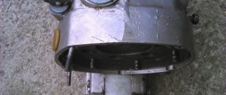
Install the front crankshaft support. To do this, heat the mounting hole in the crankcase with a hairdryer/torch.
Once warmed up, install the front support. Because the landings have not yet been gouged out, I needed a mallet, we combine the holes on the crater and on the support, and with light blows, with a mallet we upset the support itself and at the same time tighten the bolts so that the support does not move out.
We place the bolts on the thread lock and tighten them.
Next you need to prepare the crankshaft for installation. To do this, you first need to install the bearing on the front axle. The crankshaft bearings in this engine are 6208. I used FAG. Lubricate the bearing seat with a thin layer of oil, and then you need to slightly warm up the inner race of the bearing.
We position the bearing on the crankshaft so that there are no distortions, and using a suitable mandrel, with light blows, we seat the bearing.
It turned out like this
The next step is to install the crankshaft of the Ural engine into the crankcase. To do this, we orient the crankshaft so that the flywheel keyway faces upward, tilt the shaft with the rear shank down and lower it into the crankcase. We direct the connecting rods into their cylinder bores and install the crankshaft in the correct position, directing the front bearing into the front support, without distortions, since there is a possibility of damaging the bearing or the front support itself.
Next, to pull the crankshaft into place, you need to use a special puller. I used a pulley puller, the cheapest one, you can also cut out a 4mm steel plate and drill one hole in it in the center. Unfortunately, I didn’t photograph the process... In general, through this plate or puller we pass a bolt with an M8 thread, pitch 1.25. We install the puller and screw the bolt into the crankshaft, while the puller must be resting through some spacers against the crankcase so that the crankshaft moves forward. And we begin tightening, but before that, of course, we lubricate the support with oil. Next, the main thing is not to overtighten, you need to control the position of the crankshaft through the holes for the cylinders, and watch the oil catcher so that it does not rest against the crankcase and bend. I didn't do this and bent it a little. It will be a lesson