02.02.2021 9 367 Ignition system
Author: Ivan Baranov
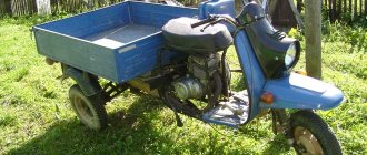
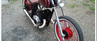
The Ant is a versatile scooter that is used by rural and urban residents as a means of transportation, a truck, and even a tractor. Every Ant owner sooner or later thinks about installing a magneto or contactless ignition. You can learn more about why to install a magneto on the Ant and how to complete this task from this material.
[Hide]
Engine
The Ant engine is somewhat different from Soviet engines of that time.
The most significant difference is in the starting system: here it can be done using an electric starter (this was very cool in the 50s) or using a manual kickstarter. There was no trace of an electric starter on any Soviet motorcycle of those years. The engine is started with the starter just like a regular car: insert the key into the ignition, turn the key all the way to the right and the engine starts.
The second difference is the forced cooling of the engine
The fan drives air through the casings, cooling the cylinder and cylinder head. The cooling system works tolerably
Mechanical clutch with cable drive from a lever on the steering wheel
The gearbox is manual, the shift lever is located on the left directly under the driver’s foot. The switching algorithm is as follows: first, second, third and fourth gears are switched up. Neutral gear is at the very beginning and to engage it you need to push the gear lever down. Controversial decision, but that's how it's done here
Twin-shaft gearbox with constant gear meshing
The engine is as simple as a broom
How to set the ignition on a walk-behind tractor - execution algorithm
Do-it-yourself tire tucking: instructions with photos and videos
From time to time, the walk-behind tractor needs to adjust the ignition system. Untimely adjustment of this unit will lead to accelerated wear of other, no less important mechanisms of the agricultural machine. In order to be able to independently adjust the ignition system on a diesel walk-behind tractor and its gasoline counterpart, you need to study the design diagrams of this unit.
A properly configured walk-behind tractor ignition system is capable of creating a spark in the right place and at the right moment. In this case, the magneto cover is responsible for distributing the resulting spark, and its lower part is responsible for interrupting the spark. In order for the ignition system to work exactly according to this principle, it must be adjusted.
The ignition installation is performed in the following order:
- First, you need to check the operation of the flywheel in the engine until the contacts located inside the magneto open;
- After this, it is necessary to measure the distance between the “anvil” and “hammer” built into the ignition system;
- Next, you will need to turn the flywheel until the piston is compressed;
- As soon as the flywheel reaches the highest point, it needs to be turned again. As a result of this, a one-time knock will be heard, indicating the operation of the overrunning clutch included in the design;
- After this, the flywheel will need to be turned counterclockwise so that the second mark on it aligns with the mark located on the body;
- The next step is to adjust the distance between the breaker contact and the adjacent cam. The minimum gap between the parts for proper operation of the ignition system will be 0.25 mm, and the maximum will be 0.35 mm;
- At the end, it remains to secure the built-in cam with a special screw, which is located on top. The video will show you how to properly set up the ignition system on a walk-behind tractor.
Diagnostics of technical condition
Easy adjustment of the handbrake with your own hands: video instructions
Diagnostics is carried out by performing the following procedure:
- The first stage is connecting the high-voltage cable to the voltage terminal.
- The second end of the cable is constantly held at a distance of about 0.5-0.7 centimeters from the device body.
- Maintaining position near the wire. Next comes a sharp turn of the rotor in the direction of rotation. The spark should jump as a result of this movement; if everything is in order, the magneto is adjusted correctly. If there is no spark or is too weak, there is a high probability that the installation requires a malfunction check. If necessary, adjustments are made.
Common malfunctions and their repairs
Here are just a few of the most common problems magneto owners may encounter:
- Failures during sparking. There are several reasons for this situation and ways to resolve the problem. Possible problems include: contacts burn, oxidize; the gap adjustment is violated; the lever cushion at the breaker is worn out; The capacitor element was broken. If an element fails, it is completely replaced. When the problem is in the gaps, they undergo additional adjustment. Contacts are also changed or completely cleaned. How to set up the magneto is described further.
- Complete lack of spark. This often happens because the transformer wiring has broken, there has been a short to ground, or the insulating layer that supplies the high-voltage cable has broken through. If problems arise with the transformer, the unit must be replaced. You can eliminate the short circuit itself or change the cable when an insulation breakdown occurs.
- A broken capacitor is the most likely cause of a spark that is too weak. In this case, the part must also be replaced.
Candle and armored wire
It is recommended to abandon the caps used for armored wires. It is better to use an alligator clip.
The armored wire itself also requires additional testing. This concerns two elements:
- Fastening in the mounting socket.
- Base for a candle.
Complete stripping of the wire from each end by 2 millimeters is an excellent reason for inspection and repair. You can check using a different armor wire instead of the one installed initially. If the spark plug is faulty, it is also replaced; the part is not repaired.
Capacitor
It is needed so that the contacts do not burn too much. It consists of two plates and insulation, the role of which is usually played by foil. Everything is rolled into one roll and placed inside the case. In some cases, if the housing is damaged, the capacitors can be adjusted using sandpaper
It is important that the structural parts do not overheat during operation. Adjusting the magneto after that won't help.
Sometimes it is recommended to install two capacitors at once, then the operation of the mechanisms will be more reliable and stable.
About breaker contacts
If they become faulty, the first recommendation is to clean the surface using a special flat abrasive plate. The work can be done without problems with a flat file with a fine notch. Cleaning with sandpaper or glass paper will not give the desired result. The contacts wear out too quickly, and in this case a flat surface cannot be obtained.
From time to time, contacts also require cleaning from plaque and adjusting the gaps between parts. The main thing is not to lose a single part during disassembly. The contact spring is subject to malfunction or straightened in the opposite direction.
Coil or transformer
It is easy to repair the tractor magneto for such parts. This same part of the engine rarely fails; it can operate uninterruptedly for a long time. If the part has become unusable, then it must be replaced with exactly the same, but working model.
Rotor
The main thing is that it does not crumble or break during operation. From time to time the rotor can become demagnetized. If the part really turns out to be damaged, then it is replaced. The main thing is not to forget to remove metal fragments, sometimes they remain inside the magneto housing. Bearings require separate inspection and lubrication.
Typical malfunctions and methods for their elimination
Now let's look at the main magneto malfunctions:
- Failures in sparking. There may be several reasons, as well as ways to solve them. This is oxidation or burning of contacts, violation of gap adjustment, wear of the interrupter device lever cushion, or a broken capacitor element. Failed elements must be replaced, and non-adjustable gaps must be adjusted. If the problem is in the contacts, they need to be changed or cleaned.
- No spark. The reason may be a break in the transformer wiring, a short to ground, or a breakdown of the insulating layer on the high-voltage cable. If the problem is in the transformer, then the unit is changed, if there is a short circuit, then it should be eliminated, and if the reason is an insulation breakdown, then the cable simply needs to be changed.
- If the spark is too weak, then most likely the reason is a broken capacitor, which will also need to be replaced.
What to do if there is no spark on the walk-behind tractor?
Replacing the king pins on a UAZ (Patriot, Loaf) with your own hands: instructions with photos and videos
If after the tests it turns out that the spark has disappeared, then the cause of this breakdown must be sought in the main elements of the ignition system of the agricultural unit.
To do this you will need:
inspect the spark plug - it needs to be unscrewed using a special key; the spark plug may be completely dry - this indicates that fuel is not entering the engine cylinder, that is, the fuel pipes are clogged or the carburetor is malfunctioning; in some cases, the part turns out to be wet from gasoline and motor oil. The reasons for this are an excess of lubricant contained in the fuel, or its leakage from the engine oil sump directly into the cylinder. In this case, the operator must remove the spark plug and dry it thoroughly. After this, you need to dry the cylinder, intensively pull the starter cable several times on the engine with the spark plug turned out; Most often, due to the lack of proper and timely maintenance of agricultural machinery, a thick continuous layer of soot and dried resinous deposits forms on the spark plug of a walk-behind tractor.
To restore the candle, you need to carefully heat it with a lighter and wash off the remaining resin with clean gasoline. After this, the part will need to be dried and screwed into place.
If this does not help, then the spark plug needs to be replaced.
It is important to proceed with extreme caution when removing, cleaning and reinstalling the spark plug.
Any careless movement can damage the electrodes of the part, causing it to no longer generate a spark.
DIY walk-behind tractor from an ant motorcycle
Ignition from the Shtil 180 chainsaw on the Ant is simple and reliable.
Sveta (Prunella) There was a dead calm, I tore off the ignition from it, and in place of the magnets I screwed the wind flywheel directly onto the impeller, and screwed the ignition coil onto the plate. That’s all. It’s a stupefied spark.
Vladimir Fesenko (Frolov)
Valentina (Muneeb) The idea is not bad, but how to protect it from moisture?
Sveta (Prunella) The reel is completely sealed, moisture is nothing to worry about and starting in the cold is a pleasure
Valentina (Muneeb) Thank you, but could you be more detailed?
Sveta (Prunella) I’ve been driving for 4 years, no problems, set the ignition, just by rotating the first magnet passes and the coil leg ends up between the magnets, this is a spark
Yuri (Kryspina) Where do you get the light from?
Valentina (Muneeb) I have big doubts about electronic ignition. Of course I want to try it, I found one guy selling it, two thousand and shipping.. Is it worth it?
Vladimir Fesenko (Frolov) Sasha, what do you want to make... why do you need electronics?
Valentina (Muneeb) I have an ant...practically new. It stood in an old woman’s barn for many years.
Valentina (Muneeb) Which one washed away? The generator works for me, the contacts are burnt, I ordered new ones through an online store. If I install it, then the electronics are reliable. I was just confused by the price
Vladimir Fesenko (Frolov) Having installed a magneto, you will not need a battery... but you have a generator (dynastarter) in your scooter, you won’t remove it... That’s where your light will come from. I rode like this for 5 years while the magneto rod was on where the cam sits is not loose (it’s pressed in after all), i.e. the magneto was not centered properly
Valentina (Muneeb) What does it mean, the contacts are the same in the magneto
Vladimir Fesenko (Frolov) When you encounter this problem... you will find me. I have been working with scooters since 1980
Homemade walk-behind tractor with TMZ engine, Ant gearbox and monolithic wheels.
Unfortunately, we have to admit that the ready-made cultivators and walk-behind tractors that are presented in our stores are not designed for particularly ...
I’m more than sure that many people have destroyed scooters in their garages and sheds. A small alteration will revive the life of iron...
Ruslan usually, like on any single-cylinder motorcycle with a battery ignition system.
Tear off a small strip of tissue paper and press it between the contacts. Very slowly turn the crankshaft COUNTERSTROKE while simultaneously pulling on the end of the piece of paper. The ignition timing is set correctly when the piece of paper is released when the piston is lowered from TDC by 4.5 - 5 mm.
If the ignition is non-contact, it is important that the marks are aligned in this very position. Maxim how much muroveine is gaining momentum, I remove the terminal from the occamulator and it starts working normally. Maxim how much muroveine is gaining momentum, I remove the terminal from the occamulator, it starts working normally
Maxim how much muroveine is gaining momentum, I remove the terminal from the occamulator, it starts working normally
Do-it-yourself walk-behind tractor - photo video drawings - Gredx.ru
My attempt to create a homemade walk-behind tractor from an Ant scooter. Drawings and diagrams... Drawing of the frame of a walk-behind tractor assembled with your own hands. Walk-behind tractor frame: 1 — steering wheel (from the Izh motorcycle); 2—mounting bracket...
Do-it-yourself walk-behind tractor: how to make a homemade unit from...
How to make a walk-behind tractor with your own hands using the example of a project from V. Arkhipov. Walk-behind tractor... Homemade walk-behind tractor from a Minsk motorcycle. Homemade ... scooter "Tula-Tourist" or T200A scooter "Ant" (14-16 hp).
Scrooge NAZIMA – Real One video premiere, 2021
Music prod. Diamond styleProducer: Cornelia PolyakProducer: Zaur ZaseevDirector of photography: Anton Zenkovich Script: Zaur Zaseev, Alexander Egorov, Anton Sheenson, Mikhail Kakuberi 1st AD: Ganna MalyshevaDirector of the film crew: Vladimir OlefirenkoHead of production: Vitaly OrelPost production supervisor: Ivan KhudoliyPost production: HoodyFX_________________________________
————————————————————All news about Black Starblack-star.ruVKontakte: vk.com/blackstargroupInstagram: instagram.com/blackstarofficialTwitter: twitter.com/black_star_ruFacebook: facebook .com/Blackstarmsk———————————————————— Brand clothing store Black Starblackstarshop.ru——————————————————— —Global Star Russia - integration of brands into artist projects / Product Placement / www.globalstarrussia.com / +7 903 181 49 39 ————————————————————Black Star Burger: blackstarburger.ru/————————————————————Barbershop / Tattoo parlor 13 by Black Star: 13byblackstar.ru/———————————— ————————Black Star Radio: blackstar-radio.ru
Adjustment
Without any instruments, you can set the ignition timing experimentally. When warmed up to operating temperature (80-90 degrees), when driving at a speed of 40 km/h, you need to switch to speed 4 and depress the gas pedal. If the electronic contactless ignition was set correctly, a short-term detonation should occur, after which the engine should begin to gradually gain speed. If valve knocking occurs, you need to turn the distributor clockwise by about a degree. The operation is repeated until the knocking stops. If, during the check, a dip in engine speed appears, the distributor is turned in the opposite direction.
In addition to adjusting the ignition timing, the new system may require carburetor adjustment. The VAZ 2107 carburetor has two adjusting screws - quantity and quality. The adjustment is carried out as follows:
- By rotating the quantity screw, the engine speed is equal to 1200-1300. Next, use the quality adjustment screw to set the maximum speed.
- Repeat the operation described in paragraph 1 until, at a speed of 1200-1300, the quality adjustment screw is set to the position corresponding to the maximum engine speed.
When installing the BSZ, experts recommend performing not only adjustments, but also cleaning and purging of the carburetor in order to see the real effect of this modernization.
1200 rub. for the photo report
We pay for photo reports on car repairs. Earnings from 10,000 rubles/month.
Write:
Now almost all classic owners install contactless electronic ignition (BSI) on their cars. And it's easy to explain. BSZ has obvious and proven advantages, such as simplicity and ease of configuration. If you are already quite tired of the fact that the contact pair, for certain reasons, very often does not work or even fails. You have not yet decided whether to buy a contactless ignition kit, then this article will help you make the right choice.
The contactless ignition installed on the VAZ will allow you to forget about problems such as oxidation and vibration of contacts, wear of contacts and the breaker cam, and others. More details
Now, let's move on to the most important thing - choosing and installing BSZ on your car.
I think that it is best to opt for a contactless ignition kit made in Russia, namely the city of Stary Oskol.
The box contains the coil, switch, wiring harness and distributor. This kit is recognized as one of the best. It’s true that the price is sky-high, and before purchasing you need to look at what engine block you have, since the distributors differ in the length of the shaft.
For installation, we will need a drill, a drill and a pair of screws; they will be useful for installing the coil in the engine compartment; some engines have a standard mounting location, but you will have to attach the switch yourself. An open-end wrench for “13”, socket or ring wrenches for “8” and “10”, as well as a wrench for “38” are also useful.
How to set the ignition timing on an Ant scooter so that the engine runs and starts well?
In order for any internal combustion engine to start and “work well” (and it is the Internal Combustion Engine installed on your scooter), you need to supply fuel to it and then ignite it at the right moment. Moreover, the engine does not work in only two cases:
- or there is nothing to burn...
- or there is nothing to set on fire...
You are interested in the second case. So:
The work of any internal combustion engine is to convert the reciprocating motion of the piston into the rotational motion of the shaft. This transformation occurs with the help of a crank mechanism (CSM). How this transformation occurs is known from the elementary school “Physics” course.
For “good” operation of the internal combustion engine, all the fuel must burn in the cylinder within a very specific time - while the shaft rotates at a certain angle. Like the picture below:
In order for the fuel to burn at the necessary moments of movement of the piston along the cylinder, it must be ignited in a timely manner. In the Ant engine, the fuel is ignited by a spark in a spark gap called a spark plug. The ignition system, consisting of the following elements, organizes the formation of a spark between the electrodes of the spark plug:
- spark plug;
- ignition coil with capacitor;
- current breaker;
- current source (battery and generator);
- connecting wires.
How the listed elements work and interact with each other can be read in the same “Physics Primer” for elementary school. Here I will only remind you that a spark in the spark plug occurs at the moment the breaker contacts open. It is this moment in time that must be captured when setting the ignition timing. “Physically” this is quite simple to do. When the current source is turned off, we clamp the strip of paper with the contacts of the breaker. Smoothly turning the engine power take-off shaft with one hand, we pull our paper strip with the other. When the contacts release the strip, at that moment the event we need will occur in the spark plug.
Now you need to organize the “spark supply” at the required moment of piston movement. This process is also not particularly sophisticated. Insert a “match” approximately 250 - 300 mm long into the hole from the inverted spark plug. By rotating the power take-off shaft, we determine the position of the piston at top dead center (TDC) and make a mark on the match. From this mark we set aside 10 mm upward - this will be the ignition point of the fuel, the position of the piston when a spark should appear in the spark plug and the fuel should ignite. By rotating the power take-off shaft, we place the piston at the ignition point. Well, now, by rotating the body of the breaker with a strip of paper clamped by the contacts, we catch the moment when they release the strip.
That's it - the ignition is installed, you can connect a working, charged battery and start the engine. If there is something to set on fire, the engine of your “Ant” should definitely start. More accurately, the ignition is installed with the engine running using a strobe light using special marks on the engine body.
This method of setting ignition timing is good because it does not require power to the ignition system.
That's it - good luck to you and the “ant” on the road...
Design
Rice. 2. Placing blocks in a scooter.
The ignition coil is protected from overheating at low speeds by a composite additional resistor SE-107, which is partially blocked by the “Start” button when starting the engine. The ignition coil should be installed closer to the spark plug. The author placed all the rest of the modernization in a special box attached to the side of the scooter (Fig. 2).
Connecting this idiotic device to many is no more difficult than plugging in a vacuum cleaner, and maybe even easier. It all depends on the desire and level of technical literacy of the owner of the Ant. On the cover of the relay regulator there are letters indicating the terminals.
Ant dino starter operating principle
The dynostarter as a device is as far from complete perfection as our VAZ plant is from the premium segment. But if at least once a season you carry out competent maintenance of the collector unit, switching equipment, and battery, then with all its inherent shortcomings, the dyno starter can last a very, very long time, up to 30,000 km, or even more.
Basic faults
- Mechanical, caused by natural wear, combustion of windings, destruction of contact groups
- Structural, due to design features
- Malfunctions of the relay regulator that lead to dyno starter failure
The most unpleasant malfunctions are related to mechanics: combustion of windings, interturn short circuit, wear or destruction of the commutator. Other mechanical faults such as wear or sticking of brushes, contamination of the commutator, breakage or oxidation of wires and terminals can be eliminated quite easily.
Diagnostics
The first sign that something has burned out, shorted or broken in the dyno starter or relay regulator is when, out of the blue, right in the middle of the road, your battery charge control lamp comes on.
If this happens to you, then the first thing you need to do is inspect the wires going from the dyno starter to the relay regulator, check the fuse, remove the cover from the relay regulator and at least visually determine the integrity of its elements, remove the rotor and see what’s wrong with the brushes and collector and if nothing suspicious is found there, turn to a very competent electrician for help.
You can try to identify the fault yourself, and within the framework of this article it would be possible to describe all the stages of testing, including the author’s developments, but none of you will do this. In the best case, poke it a couple of times with the tester and you’ll give up on this matter, or even end up using a magnet instead of a dynostarter.
The second sure sign that your dyno starter is in perfect order, but it’s just time to service it, is when, at idle and low engine speeds, the charge warning lamp first begins to blink slightly, then begins to burn more steadily and after a while begins to burn at full intensity throughout engine speed range.
In both the first and second cases, without disassembling the dynostarter, little can be learned about its condition, so if there are any complaints about its operation, we roll up our sleeves, prepare the tool and get started.
Disassembly
We remove everything that interferes with the removal of the rotor, hold the rotor by the fan with your hand and unscrew the nut
A good owner should have a washer and a lock under the nut. The bad one won’t even have a nut...
Remove the rotor from the crankshaft. The rotor can be removed either with a factory puller or with a homemade one - it makes no difference.
First of all, we inspect the rotor commutator and brushes. The commutator must not show any wear or damage. For example, this collector is just dirty and after we wash it, the dynostarter will start working again.
And some deer broke out the lamellas of this collector. Such a rotor will be difficult to help and easier to throw away. To prevent this from happening to your rotor, select bolts for the coupling for the magnet and the fan of the appropriate length, and do not put everything you have on hand there...
This collector was pulled up by something, the lamellas were shorted together and the dynostarter died. If you find a good turner, he will be able to sharpen the scuffs and the rotor’s performance will be restored.
There are situations when the rotor is dropped or the windings are hit. You understand that damage to the power windings will not improve the reliability of your scooter’s power supply system, so handle such devices very carefully and use pullers, and do not knock them down like tractor drivers with a hammer.
On this rotor, someone smacked the windings with relish.
Cleaning the collector
Take a small screwdriver and clean out the dirt between the slats. The collector must be cleaned very carefully so as not to scratch the lamellas.
After cleaning, blow the collector with compressed air, wash it with clean gasoline and wipe it dry with a rag.
When the gasoline has completely evaporated, take a piece of some lint-free cloth, moisten it a little in gasoline and carefully rub the collector with the maximum possible force until it is perfectly clean.
Checking the rotor windings
We switch the tester to the continuity mode and check the winding contours for breakdown: we place one probe on the rotor body, and with the second we touch all the lamellas in turn. If the tester beeps on any lamella or displays a lot of numbers on the screen, the winding is broken and the rotor should be replaced.
Checking the stator windings
We unscrew the stator mounting bolts, tap it around with a wooden mallet, remove it from the engine, turn it over with the wires towards you, switch the tester to the continuity mode, connect the tester probes to the two rightmost terminals of the windings, if the tester beeps, there is no winding breakage.
We do the same with the remaining two wires: put the tester into dialing mode, connect the tester probes to the ends of the wires, if the tester beeps, there is no winding break.
How to set the ignition on a walk-behind tractor?
The following signs will indicate the need for urgent adjustment of the gap in the ignition system:
- the need to frequently pull the starter cord to no avail;
- delayed reaction of the walk-behind tractor engine to manipulations with the starter;
- complete lack of starting the internal combustion engine of the agricultural unit.
Each of these malfunctions indicates that the operator must install the ignition of the walk-behind tractor used on the farm. The correct procedure for this can be found in the operating instructions for the existing equipment. However, the operator does not always have the manual at hand. In this case, the gap between the built-in ignition module and the flywheel can be set in the following sequence:
- First, the operator must close the spark plug with a special square;
- Then its body will need to be pressed against the head of the standard cylinder of the internal combustion engine;
- Next, the spark plug must be turned in the direction opposite to the hole provided in the end of the chrome-plated cylinder;
- After this, you need to carefully turn the crankshaft of the internal combustion engine of the walk-behind tractor - to do this, just pull the trigger cord;
- As a result of these actions, a bright blue spark should jump between the built-in electrodes. If this does not happen, then it is necessary to check the distance between the magneto and the starter of the walk-behind tractor - it should be from 0.1 to 0.15 mm. If these requirements do not meet these requirements, the gap between the elements will need to be adjusted.
Many experienced users adjust the ignition of a walk-behind tractor by ear. Both contact and non-contact magnetos are suitable for this. To configure the system yourself, you must:
- Start the engine and slightly loosen the standard distributor;
- Slowly turn the breaker in each of the possible directions;
- Achieve maximum speed of the factory engine and quickly secure the structure;
- Listen and find the moment at which a spark instantly appears;
- Turn the breaker until there is a clear clicking sound;
- Fix the standard distributor fasteners.
In some cases, a strobe light will help to correctly adjust the existing gap.
To configure you need:
- Warm up the power unit of the walk-behind tractor;
- Connect the device to the electrical power supply network of the agricultural unit;
- Install the sound sensor on a high-voltage wire connected to one of the cylinders of the standard internal combustion engine;
- Carefully remove the vacuum tube and plug it with any available means;
- See where the light from the strobe will be directed - it should “look” towards the standard pulley;
- Start the engine and leave it idling;
- Scroll the distributor;
- Once the marks on the built-in pulley line up with the mark located on the cover of the device being used, turn the factory breaker nut all the way.
Each of these methods is suitable for adjustment on both gasoline and diesel walk-behind tractors. The main thing in the process of self-tuning is not to remove the coil and other elements of the ignition system - this can lead to disruption of the operation of the entire unit.
How to set the ignition to a magneto on an ant
VIDEO ON THE TOPIC: Setting the ignition on the ant correctly!
Moreover, the engine does not work in only two cases:. The work of any internal combustion engine is to convert the reciprocating motion of the piston into the rotational motion of the shaft. This transformation occurs with the help of the crank mechanism of the crankshaft. As in the picture below:.
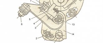
Parts for installing a magneto on an Ant scooter: 1 magneto adapter, 2 attachment to the dynastarter rotor, 3 attachment to the magneto rotor. Filmed on the basis of Melitopol Professional Agrarian. Ant is a universal scooter, which is used by rural and urban residents as a means of transportation, a truck and even a tractor.
How to install a magneto on an Ant scooter. For a villager, “Ant” is everything: a motorcycle, a car, a tractor, and a truck. 8 he is indispensable on the farm. And what a shame it becomes when the batteries “die”. In rural areas there has never been an abundance of them, you can’t drive them into the city (and you can’t drive a scooter anyway!), and besides, there’s no guarantee that you’ll buy them.
And without a battery, the Ant becomes weaker than its biological brother, turning into a helpless paralytic. I had to approach the problem from the other side - abandon the battery altogether. This was done by installing a magneto on the scooter from the tractor launcher of the decommissioned Belarus.
To do this, it was necessary to make an adapter, attachments for the dynastarter rotors and a magneto. They are machined from steel and then hardened. Installation is carried out in the following sequence. Having removed the coupling from the rotor, it is replaced with a magneto rotor attachment. Then, instead of the breaker, cam base and cam removed from the dynastarter, a dynastarter attachment is installed.
The latter is fixed with the same screws that secured the base of the breaker. Three holes with a diameter of 7 mm are drilled in the fan cover, necessary for attaching the magneto adapter. The adapter itself is needed to strengthen the rather fragile cover. Be sure to place plain and split washers under the fastening nuts. The cover with the adapter is fixed in place.
Having installed the piston at a distance of 2.8-3.2 mm before TDC, “put” the magneto on the adapter so that the protrusion of its nozzle fits into the slot of the dynastarter rotor. Now, turning the magneto body, you should determine the moment of opening the contacts, and then, noting the position, mark the mounting holes. M6 thread is used. All that remains is to connect the high-voltage magneto wire to the spark plug cap, and connect the wire from the terminal on the housing to the ignition switch.
In the “Off” position, this wire should be shorted to ground; in the “On” position, it should be open. Long-term operation of a scooter with a magneto is successful. No problems starting either in summer or winter, the engine runs great. The dynastarter continues to generate electricity, which is more than enough for lighting and alarm systems.
In contrast to the method of installing a magneto on a scooter, proposed by A. Platonov (“Moto”, 1992, No. 1), I think that mine is much more convenient - you only need to make three simple parts instead of five complex ones. This will require less time and expense. In addition, at any time you can quickly return to the standard dynamo battery ignition system.
Parts for installing a magneto on an Ant scooter: 1 — magneto adapter; 2 — attachment to the dynastarter rotor; 3 — attachment to the magneto rotor.
anthill scooter
I'll give my two cents.
First, decide what the scooter will be used for and how often it will be used. A 2000 year old is probably fine, so leave the working system alone, but put the battery at 12V/17H, go easy and start with the key. Tens of thousands of people must travel to disable a dynastarter.
As for the cam ignition, with all its shortcomings, it seems that the timing is not entirely accurate and so on. It has one big advantage - simplicity. Three details you can see and touch. Moreover, mechanics almost never surprise, which is not the case with electronics.
When problems arise, it is best to address them when they become available. Like any equipment, ants have their problems (with the dynastarter, clutch, carburetor, etc.). However, for many, this method has worked for decades with minimal care.
Well done admin Published March 25, 2011 - 16:51
The generator and starter in the same dynastar bottle remain in place, the switch is removed from the ant. An adapter is made between the shaft and the end of the crankshaft, the front panel is placed on the dynastarter housing, and a magnet is attached to it. Since the magnet will protrude, you will need to make a cutout in the hood. Were there diagrams and pictures in motorcycle magazines for 9? of the year. It was converted into a magnet and into a Voskhod generator. I liked the version with a generator better - in 20 years of operation, I changed the switch once, and that was all the maintenance.
Emil30_30 Published January 28, 2013 - 13:46
Members, I have a question for you. but in general it is possible to restore the entire enton mechanism, today I looked at the failure genes going to the coil and since I bought it second hand I would like to know if there is a relay that can be used instead of the usual one (pp-121 / 2903.3702) , since it is impossible to find it now, if you tell me I will be grateful.
Emil30_30 Published January 28, 2013 - 19:49
Home // How to install the ignition on a film anthill | | rel = 0; control = 0; showinfo = 0; iv_load_policy = 3;" frameborder =»0″ Fullscreen>
Sleeves on scooters. How to set up a magnet.
Subscribe to the new channel. https://m.youtube.com/channel/UCMds5tPNqtfKfhl-mOmQFTw.
Installing a magnet on an Ant motor, part 2
Installing a magnet on an Ant engine (part 2)
In each case, the reason may be completely different, so you must understand it deeply. Three holes with a diameter of 7 mm are drilled in the fan cover, which are necessary for attaching the magnetic adapter.
Like most Soviet equipment, this cargo scooter is reliable and easy to use, but a little rough around the edges.
How to set the ignition timing on an Ant scooter so that the engine runs and starts well?
In order for any internal combustion engine to start and “work well” (and it is the Internal Combustion Engine installed on your scooter), you need to supply fuel to it and then ignite it at the right moment. Moreover, the engine does not work in only two cases:
- or there is nothing to burn...
- or there is nothing to set on fire...
You are interested in the second case. So:
The work of any internal combustion engine is to convert the reciprocating motion of the piston into the rotational motion of the shaft. This transformation occurs with the help of a crank mechanism (CSM). How this transformation occurs is known from the elementary school “Physics” course.
For “good” operation of the internal combustion engine, all the fuel must burn in the cylinder within a very specific time - while the shaft rotates at a certain angle. Like the picture below:
In order for the fuel to burn at the necessary moments of movement of the piston along the cylinder, it must be ignited in a timely manner. In the Ant engine, the fuel is ignited by a spark in a spark gap called a spark plug. The ignition system, consisting of the following elements, organizes the formation of a spark between the electrodes of the spark plug:
- spark plug;
- ignition coil with capacitor;
- current breaker;
- current source (battery and generator);
- connecting wires.
How the listed elements work and interact with each other can be read in the same “Physics Primer” for elementary school. Here I will only remind you that a spark in the spark plug occurs at the moment the breaker contacts open. It is this moment in time that must be captured when setting the ignition timing. “Physically” this is quite simple to do. When the current source is turned off, we clamp the strip of paper with the contacts of the breaker. Smoothly turning the engine power take-off shaft with one hand, we pull our paper strip with the other. When the contacts release the strip, at that moment the event we need will occur in the spark plug.
Now you need to organize the “spark supply” at the required moment of piston movement. This process is also not particularly sophisticated. Insert a “match” approximately 250 - 300 mm long into the hole from the inverted spark plug. By rotating the power take-off shaft, we determine the position of the piston at top dead center (TDC) and make a mark on the match. From this mark we set aside 10 mm upward - this will be the ignition point of the fuel, the position of the piston when a spark should appear in the spark plug and the fuel should ignite. By rotating the power take-off shaft, we place the piston at the ignition point. Well, now, by rotating the body of the breaker with a strip of paper clamped by the contacts, we catch the moment when they release the strip.
That's it - the ignition is installed, you can connect a working, charged battery and start the engine. If there is something to set on fire, the engine of your “Ant” should definitely start. More accurately, the ignition is installed with the engine running using a strobe light using special marks on the engine body.
This method of setting ignition timing is good because it does not require power to the ignition system.
That's it - good luck to you and the “ant” on the road...
Attention! It is important!
Eccentric adjustment
To adjust the spark generation (current strength) of the magneto, you need to rotate the weakened eccentric (cam) relative to its shaft and achieve the highest current power.
Stand: the drill rotates, the end of the stripped armored wire is brought to the magneto body at a distance of 5 mm. If the current is insufficient or does not exist at all, now let’s proceed to adjusting the cam (aka eccentric). Stop the drill. The cam is secured to the shaft with one screw and washer in the center of the shaft.
Loosen the screw. By inserting a screwdriver into the grooves of the cam, we turn the cam relative to its axis on the shaft by approximately 1 mm clockwise. Secure the cam with a screw. Turn on the drill. We look at the spark. It should be at a distance of 5-7 mm from the body. Turn off the drill.
This procedure must be repeated until you get the best result. It takes me from 20 minutes to an hour to fully adjust the eccentric. But it's worth it! When the best result is achieved, on this mounted stand you can also adjust the current strength by adjusting the size of the contact gap and selecting a capacitor. Provided that the contacts are not burnt, even and smooth, and the capacitor and coil are working, the spark will be like lightning!
VKontakte group: https://vk.com/tmz_engine
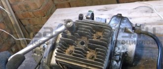
Things went wrong
Of course, the engine had to be half charged with spare parts made by no one. I suspect that the counterfeit goods with which I had to tinker for the last two days are being produced in some garage in Rostov-on-Don, or that the local workers are secretly making this nonsense at the factory. In any case, according to my information, traders bring this disgusting stuff from Rostov. The engine to which I have devoted the last two days has already been converted to a magneto. I don’t know why he bought it - I didn’t ask him for it. The old one was in good condition. Well, since I bought it, we’ll install it. It’s none of my business, of course, but I have an extremely negative attitude towards this kind of collective farm tuning.