Operating cycle of a four-stroke engine.
As the name suggests, the working cycle of a four-stroke engine consists of four main stages - strokes.
1. Inlet. During this stroke, the piston descends from top dead center (TDC) to bottom dead center (BDC). At the same time, the camshaft cams open the intake valve, and through this valve a fresh fuel-air mixture is sucked into the cylinder.
2. Compression. The piston moves from BDC to TDC, compressing the working mixture. In this case, the temperature of the mixture increases significantly. The ratio of the working volume of the cylinder at BDC and the volume of the combustion chamber at TDC is called compression ratio. The compression ratio is an important parameter; usually, the higher it is, the greater the fuel efficiency of the engine. However, an engine with a higher compression ratio requires fuel with a higher octane number.
3. Combustion and expansion (piston stroke). Shortly before the end of the compression cycle, the air-fuel mixture is ignited by a spark from the spark plug. During the piston's journey from TDC to BDC, fuel burns, and under the influence of the heat of the burned fuel, the working mixture expands, pushing the piston. The degree to which the engine crankshaft (CS) is “underrotated” to TDC when the mixture is ignited is called the ignition timing angle (IAF). Ignition timing is necessary so that the bulk of the fuel-air mixture has time to ignite by the time the piston is at TDC (the ignition process is a slow process relative to the speed of operation of the piston systems of modern engines). In this case, the use of energy from burned fuel will be maximum. Fuel combustion takes almost a fixed time, so to increase engine efficiency, it is necessary to increase the CV as the speed increases. In older engines, this adjustment was made by a mechanical device - a centrifugal regulator acting on a chopper. In more modern engines, electronics are used to adjust the SPD.
4. Release. After BDC of the operating cycle, the exhaust valve opens and the upward moving piston displaces the exhaust gases from the engine cylinder. When the piston reaches TDC, the exhaust valve closes and the cycle begins again.
It must also be remembered that the next process (for example, admission) does not necessarily have to begin at the moment when the previous one (for example, exhaust) ends. This position, when both valves (intake and exhaust) are open at once, is called valve overlap. Overlapping the valves is necessary for better filling of the cylinders with the combustible mixture, as well as for better cleaning of the cylinders from exhaust gases.
From all this we conclude that: 1 - to ignite the working mixture, it is necessary to form a spark on the spark plug; 2 - the moment of spark formation should shift in time depending on the crankshaft rotation speed.
BSZ to the Urals
Now I’m far from the Urals, and I can’t show you with a live example, and when I arrive, the season will end.
I promise to supplement the entry with drawings and photos upon arrival. In the store we buy a travel sensor from a VAZ, a switch, an ignition coil from the Oka, two armored wires for this coil with calculation of the installation location (I took it with L-shaped caps and attached it behind the generator), a wiring harness for the BSZ classic. The most creative moment is to make a drawing and carve a curtain according to it. Here I found general types of finished curtains.
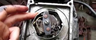
I hope you understand roughly?! And now in more detail. We find an automatic ignition advance machine like the one on the box, if there is a beep. We remove the lower part along which the contact runs; it is secured with a retaining ring. We replace the fit on the machine so that the curtain does not play on the axis of the machine, the play must be selected in two planes: radial and axial, it is better to then modify it with a file and a reamer. I don’t remember the dimensions, except for one thing, the thickness of the wing was 2 mm, then I sharpened it to 1.5 mm, I recommend 1.5 mm since there is less chance that it will interfere with the sensor. The blind is made by a turner as a round part; we make all the slots ourselves. The height of the curtain should be such that the sensor can be adjusted to fit it and does not catch the machine. After turning, we make a cut like on the sleeve that we removed from the machine, just don’t mix up the side, otherwise the curtain will turn out upside down and connect the curtain with the machine and the locking ring, we get a result approximately like in the picture. We make a mounting platform for the sensor from a 1mm sheet of iron or an old platform as in the photo.
Putting everything in place.
We set the TDC, set the platform in the center and mark the sensor on the curtain on both sides. After that, we take everything back and mark the center between the two lines on the curtain, draw a continuation of this line through the center of the curtain; this will be the moment of the spark; at this moment the curtain should be interrupted, i.e. you need to make the horn more than a centimeter wide clockwise, then the design options are different, the first example is an exact copy, and the second type will be vaguely reminiscent of the detail in the photo with the second example
We put everything back together, connecting it according to the diagram.
And it can be adjusted using a diode lamp by connecting the plus of the lamp to the indication wire of the hall sensor, and the minus to ground when the ignition is on. I installed the switch under the tank. Continued at www.drive2.ru/b/2382966/
Comments 41
Should the curtain be 30 degrees?
The main thing is where it ends, if my memory serves me right, then at that moment the Spark occurs
Where can I buy such a curtain?
I ordered from a turner or they sell the BSZ installation kit
What's the kit for?
I think they are called BSZ for the Ural motorcycle
What's the kit for?
I don’t know, I have no problems with the contact, it’s original - 27 years old - 50 thousand miles, I think I changed the cams, I don’t remember, and that’s it, we have a fishing and hunting region. There are a lot of Urals, people actively drive them, many have installed them century and from vases - for some reason the commutator burns out quickly - everyone is afraid of heating, and it’s not good - don’t remove the wiring from the camulator - the commutator is screwed, don’t remove the candle holder - the coil is screwed, I think this kind of ignition is only relevant when installing a second spark plug on the cylinder - but it’s also not an option if you actively knead shit - in short, the device is for infantile motorists who never leave the asphalt, and the problem with the constantly burning Ural relay was solved by installing two penny relays from the vase - and it does not charge at high speeds, but the moto-light switches on immediately after the factory it goes out and lights up only after turning off the ignition - at very low speeds it works from the gene - checked by disconnecting the battery - one thing, but when the light is turned on, the power of the standard gene is not enough and works intermittently or even stalls, I will also solve the problem - I’ll install a gene from MTZ - there’s generally a relay it’s not necessary and in my opinion it even starts from a pusher without an Akum - if you can get a running start while pushing the Urals at the same time 30 km per hour
Device of contact ignition system.
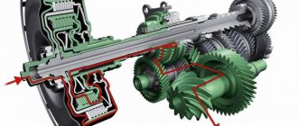
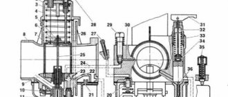
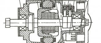
In a classical mechanical safety system, all this is managed by one device - a breaker, a mechanism that determines the moment of formation of high-voltage pulses in the safety protection system of gasoline internal combustion engines. In its classic form, the device includes a low voltage current breaker and a centrifugal ignition timing regulator. The breaker contacts open at a certain moment, breaking the primary circuit of the ignition coil winding (SC), which causes the induction of a high voltage current in its secondary winding. A capacitor is connected parallel to the contacts to reduce sparking. The centrifugal regulator changes the SOP according to the change in the rotation speed of the CV. Let's consider its work using the PM-302 as an example.
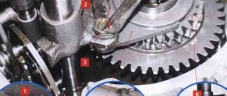
The breaker consists of a fixed body with contacts and a capacitor, an eccentric rotor with a centrifugal regulator and a drive fork. The rotor rotates on the nose of the camshaft (CV), but is not rigidly connected to it - the rotor is driven through a drive fork, which is fixed on the flats of the CV. The shape of the eccentric is such that when the rotor rotates, the contacts on the housing periodically (2 times per 1 revolution of the rotor) close and open. The centrifugal regulator, which is a spring-loaded weight on a parallelogram frame, moves the rotor relative to the drive fork as the speed increases, shifting the point of contact opening, and consequently spark formation, which becomes earlier.
This design is quite simple and reliable. however, it has a number of disadvantages: - springs must be carefully selected for uniform operation across the cylinders and the correct SOP schedule. Over time, the springs become deformed, which leads to engine malfunction. It can be eliminated by replacing the springs (a selection of them in pairs is required). — the accuracy of reproduction of the SOP graph is affected not only by the state of the springs of the centrifugal regulator, but also by the state of the return spring of the contact itself, because the rotor eccentric also has to overcome its resistance. This fact is not obvious and is often ignored by many users. — contacts that switch short circuits burn out over time, which leads to a shift in the point of sparking. It can be eliminated by cleaning the contacts and re-adjusting the ignition. To prevent this phenomenon, the contacts must be made of a refractory alloy, which is not done in modern products. — the exclusively mechanical nature of the ignition timing mechanism determines the only SOP schedule, which cannot be changed. Depending on the engine capacity, transmission gear ratios, and operating conditions, this SOP schedule may be far from optimal.
Examination
If there is any suspicion of problems with the ignition, you should check that it is working correctly. Diagnosis is carried out in the following order;
- We check the mechanical component of the unit. We look to see if the cam mechanism is stuck; if there are problems with mobility, then it is worth checking its performance. Be sure to measure the gap between the cams; most often it turns out to be too small, which prevents sparks from forming;
- The next step is to check for the presence of a spark. To do this, turn on the ignition and force the cams to move using a screwdriver, creating a gap. The spark should be blue and white. If it is red or orange, then you need to look for a malfunction.
- We take a multimeter and measure the resistance at the bobbin terminals. Attention! The ignition must be turned off. On the primary winding the resistance should be 6 Ohms, on the secondary winding 10 Ohms;
- The resistance between ground and terminals is checked, in optimal condition it should be 6-15 Ohms, if more, then the problem is in the wire;
- The tester is also used to ring high-voltage wires. If the resistance tends to infinity, then it is worth replacing the wire; it is better to do it as a set;
- The last step is to check the condition of the candles. Electrodes should have a sand color. It is recommended to maintain a distance of 0.6 mm between them.
Actually, this is all that should be checked. Microprocessor varieties are also checked in approximately the same way. SoveK ignition is of this type.
Adjustment
If you have identified a problem with out-of-phase phases, then you just need to find out how to set the ignition on a Ural motorcycle. This will make your life much easier in the future. Please note that the electronic ignition on the Ural motorcycle is regulated completely differently.
So, you need to adjust the ignition of the Ural motorcycle. To work, you will need wrenches, a screwdriver, and it is advisable to take a test light. Adjustments are made in the following order:
- First, set the engine to the top dead center position of the first cylinder, and this should be the compression stroke. You can check this as follows: unscrew the spark plug, plug the hole with paper and crank the engine. When the resulting plug is knocked out, you can stop, this is the desired position.
- Loosen the fastening of the breaker body, after which it is turned all the way clockwise, and a 12-volt test light is connected to the contacts;
- Turn on the ignition and turn the breaker housing until the light turns on. As soon as it lights up, you should stop and secure the lid. This completes the setting of the advance angle.
Izh Jupiter 5 ignition adjustment is done in approximately the same way. Now you know how to configure this system on your motorcycle.
Previous entry Installing electronic ignition on a Ural motorcycle
Next entry Restoring a Ural tuning motorcycle
Electrical diagram of the car DNEPR - MOTORCYCLE
Electrical circuits of Dnepr motorcycles of various modifications - Dnepr MT-10, Dnepr 11, Dnepr 16 other models.
To enlarge the diagram, click on it. Electrical circuit of the motorcycle Dnepr MT-10
Electrical circuit of the motorcycle Dnepr MT-10 36
1 — left turn signal light Dnepr MT-10, 2 — lamp A12-21; 3 - headlight; 4 — lamp A12-4 for side and parking lights; 5 — lamp A12-45-40 high and low beam; 6 — right turn signal lamp (not connected on a motorcycle with a sidecar): 7 — speedometer; 8 — lamp A12-1 speedometer lighting; 9 — indicator lamp for direction indicators; 10 — warning lamp for emergency oil pressure; 11 — high beam warning lamp; 12 — generator warning lamp; 13 — neutral sensor warning lamp; 14 — instrument panel; 15 - central switch; 16 — direction indicator switch; 17 — turn signal switch; 18 — contact plug; 19 — emergency oil pressure sensor; 20 - light switch; 21 — front light of the stroller 22 — lamp A12-21 for side light and brake signal on the stroller; 23 — fuse block; 24 - generator; 25 - signal; 26 — relay-regulator: 27 — brake signal switch, 28 — Dnepr MT-10 switch; 29 — battery; 30 - breaker; 31 — ignition coil; 32 - high voltage wire; 33 - spark plug tip; 34 — spark plug; 35 — rear light of the stroller; 36 — headlight of the Dnepr MT-10 motorcycle; 37 - lamp A12 15 brake signal; 38 - lamp A12-3 for the side light of the license plate lighting.
Electrical circuit of the motorcycle KMZ-8.155 Dnepr-11 and KMZ-8.922 Dnepr-16
Electrical circuit of the Dnepr-14 motorcycle
1 – emergency ignition switch 2 – day-night switch 3 – connector blocks Dnepr 14 4 – right turn indicators with lamp A12-21 (on a single motorcycle) 5 – handbrake brake light switch 13.3720 6 – speedometer scale backlight lamp A12-1 7 – indicator lamp for direction indicators А12-1 8 – indicator lamp for emergency oil pressure А12-1 9 – indicator lamp for high beam 10 – headlight lamp А12 –45+40 11 – side light lamp in the headlight А12-4 12 – ignition switch 141.3704 13 – left direction indicators with lamps A12-21 14 – relay-interrupter of direction indicators RS 427 15 – direction indicator switch 16 – light switch Dnepr 14 17 – right direction indicators with lamps A12-21 (on a sidecar) 18 – lamp A12-8 of the front side light (on the sidecar) 19 – emergency oil pressure sensor 20 – fuse block 21 – relay-regulator 33.3702 22 – indicator lamp for generator operation A21-1 23 – indicator lamp for neutral in the gearbox A21-1 24 – sensor for switching on the neutral warning lamp 25 – sound signal S-205 26 – ignition coil B-204 27 – breaker PM-302A 28 – horn button 29 – double-filament lamp A12-2+6 for high beam and brake light (on a wheelchair) 30 – foot brake brake light switch 31 – brake light lamp A12-21 32 – tail light lamp A12-5 33 – maesa switch 34 – battery 6MTS-9 or 2KhZMT-6 35 – socket (only on Dnepr -16") 36 – generator G-424 and rectifier 37 – relay RR-330.