Ural motorcycle clutch device
The motorcycles of the Irbit Motorcycle Plant use a dry double-disc clutch (Fig. 1).
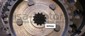
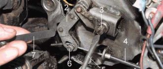
The drive disks (pressure, intermediate, thrust) are made of steel. The working surfaces of all disks are polished. In the center of the pressure plate there is a square hole, and in front there are recesses for springs. The pressure and thrust discs are centered on the flywheel pins and can move freely along them in the axial direction. The thrust disk is attached to the fingers with countersunk screws. The screws are locked by punching the metal of the disk into the screw slot. To properly assemble the Ural motorcycle clutch and maintain the balance of the flywheel and clutch, marks are applied with a core on the discs and on the annular edge of the flywheel, which are aligned during assembly. Friction linings are molded to the steel driven disks and splined hubs are riveted to transmit torque. The clutch release rod on the Ural motorcycle has a square shank, which prevents the rod from turning in the pressure plate. The rod together with the tip rotates relative to the slider in the thrust bearing. The slider, due to the action of the lever, moves forward in the axial direction and, through the bearing, tip and rod, moves the clutch pressure plate and separates the disks, as a result of which the transmission of torque stops. If the force is removed from the lever, then under the action of springs the disks move back, returning the rod, tip, bearing, and slider to their original position.
The disks are pressed against each other by springs, and friction forces arise, which transmit torque.
If the lever is released smoothly, the discs are pressed against each other gradually, the friction forces increase smoothly, the torque will increase gradually, due to which the Ural motorcycle moves off smoothly.
If the torque exceeds the calculated value, for example due to the inertia of the flywheel at high speeds, then when the engine and transmission are rigidly connected, destruction of parts may occur. If there is a clutch, if the calculated value of the torque is exceeded, the friction forces of the discs are not enough to transmit such a torque, the discs slip relative to each other, protecting the parts from destruction.
The clutch is controlled by a lever on the left side of the steering wheel. When you press the lever, the force is transmitted through a flexible cable (Bowden cable) to a lever on the gearbox, which acts on the slider and disengages the clutch.
Since the clutch parts wear out during operation, the position of the clutch lever on the gearbox changes - the free play of the lever increases, and clutch control is disrupted. To regulate the correct engagement and disengagement of the clutch on the Ural motorcycle, there are adjusting screws on the cable, which are used to achieve such a position so that when you press the clutch release lever on the steering wheel before the discs begin to separate, the free play of the lever is 5-8 mm. Free play is measured at a distance of ¾ of the lever length from the axis of rotation.
To check the free play, the lever on the gearbox must be moved to the rearmost position, while the lever on the steering wheel will turn all the way into the bracket (clockwise). Next, you need to move the lever on the steering wheel towards you. At first, the lever should move almost without force, and at the moment the clutch begins to disengage, with force. The distance by which the lever on the steering wheel moves before the force begins to increase is called free play. If there is no free play, the clutch control parts will prevent the clutch discs from pressing tightly. In this case, the friction forces between the disks will be small, which will lead to incomplete transmission of torque. In this case, the clutch “slips” and the speed of the Ural motorcycle does not increase with increasing engine speed.
The reason for clutch slipping on a Ural motorcycle can also be oil from the engine or gearbox getting on the discs when the seals are destroyed, since this reduces the coefficient of friction of the discs and the clutch slips. As a temporary measure to eliminate this defect, it can be recommended to pour gasoline into the flywheel cavity through the inspection window to install the ignition and turn the flywheel using the kickstarter, simultaneously turning the clutch on and off. This operation must be performed quickly to avoid gasoline leaking out of the flywheel cavity. However, at the first opportunity, it is necessary to eliminate the cause of oil getting on the discs.
Sometimes, even with proper adjustment, the clutch “leads,” which is caused by warping of the discs, which occurs when the clutch overheats. This occurs during prolonged operation with the clutch slipping, for example, when driving at very low speeds, during prolonged driving in difficult road conditions (mud, sand, snow, potholes), when you have to use the clutch frequently. It is advisable to avoid driving in such conditions, since not only the clutch, but also the engine may overheat.
Another tuning of the Chinese moped Stels 400 Enduro. I'm tired of the extremely tight clutch with a dead cable (it's crap from the factory). By the way, the cable in the stock turned out to be “butt” and when replacing the steering wheel it was already strongly stretched on its own. I placed the steering wheel slightly higher than the stock one for ease of riding in a standing position. Frightened by the soft clutch of the KTM, I thought it was worth looking for a hydra. And I found it. The same ketai as everything else, but like a universal clutch. I ordered it, waited, fortunately it’s inexpensive:
But first, I went around to the showrooms with Chinese mopeds and clicked the clutches on them. As it turned out, on all Ketais (kayos, snow leopards) the clutch is tight and the cables seem to feel rusty. Not my option. The only normal soft clutch was found on the asiawing. I tried to install a car from this moped. It got better, but not much.
The cats are testing a new lever.
While I was playing with the cables, the order and the hydra arrived. The kit arrived already assembled, the machine was pumped. The only thing I had to do was loosen the hose on the cylinder and turn it in the other direction. Tests are a natural place to start. I somehow fixed it with zip ties and rolled a little without even removing the old cable. You need to understand whether it makes sense to install it at all and whether the piston stroke in the cylinder is enough to fully depress and release the clutch.
Wild collective farm:
In principle, it’s normal, there’s enough movement, it doesn’t lead, it doesn’t slip. But the standard remote control prevents full squeezing, something will have to be decided about this. The tests have been passed, it is necessary to install. I dropped the tank, laid a hose and began to farm some random stuff to increase the length of the rod from an old cable. Nothing special, a steel plate, a Dremel, a drill, a file and an old cable cutter.
Cultivated collective farm:
I had to slightly bend the mounting bracket on the frame because... The cylinder did not fit into it slightly. Once assembled, it all looks more decent:
I forgot to put on the boot from the old cable, I corrected it:
The lever also required a little filing. I don’t know why there is this idiotic cut in the lever, but its edge is especially sharp and cuts your fingers.
Correcting:
Well, the appearance:
Immediately lubricate all moving parts of the lever, especially the piston pad.
In principle, that's all, the rod extension took the longest to make; if it is not needed, installation will take 20-30 minutes.
I can’t say anything definite about work yet. The squeezing did not become much easier, but it became soft and clearly readable, there are no jerks or squeaks like the cable one. The lever travel is large, it's fine with my fingers, but it will be difficult for short fingers to reach it. To avoid slipping/driving, I had to turn the adjustment all the way down. I can't say anything about reliability yet. At -20 the clutch works without pressure. From the tests, several kilometers on compacted snow. I hope it won’t die in a month) Before spring I’ll test it on enduro, if it works and doesn’t die, I’ll order the same thing for ninja. The price is 1500-2500 from the Chinese.
PS Re-uploaded the post and corrected the photos.
Ural motorcycle clutch device
Chapter IV. TRANSMISSION OF MOTORCYCLES “URAL”, “DNEPR”
The transmission is designed to transmit torque from the engine crankshaft to the wheel(s) of the motorcycle, change it and stop the transmission of rotational force.
The transmission consists of a clutch, gearbox, driveshaft and final drive.
CLUTCH OF MOTORCYCLES “URAL”, “DNEPR”
The clutch is designed to transmit torque from the engine to the gearbox, disconnect the engine from the gearbox during gear changes, and smoothly engage when the motorcycle is moving away. The double-disc dry clutch consists of driven and driven parts and a clutch release mechanism.
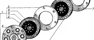
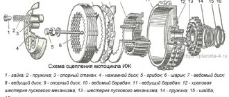
Rice. 4.1. Clutch discs of the motorcycle “Dnerpr-11/16. 1 — disk assembly; 2 - hub; 3, 5, 6, 7 - disks; 4 - spring; 8 - screw; 9 - rivet
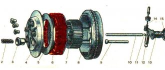
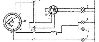
Rice. 4.2. Clutch release mechanism: 1 — cotter pin; 2 — washer: 3 — ring; 4 - slider; 5 - bearing, 6 - tip; d 1 - rod, 8 - oil seal; 9 — rod assembly, 10 — lever; 11 - bolt; 12 - nut; 13-axis
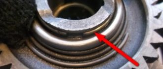
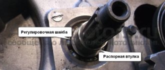
The need to check clutch parts arises if the clutch pins and pin holes in the drive discs wear out, the pin fits in the flywheel become loose, the splines in the hub of the driven discs wear out, the fastening of the disc hubs becomes loose, the friction discs wear out and the elasticity of the springs decreases. If the fingers are worn out by more than 1 mm, they need to be replaced. To do this, press out the worn pins, having previously measured the amount of protrusion of the ends relative to the plane of the flywheel. Press in new fingers (Fig. 4.3), leaving an allowance at the ends for grinding. Then the fingers are polished. After grinding, the ends of the fingers should be in the same plane. The runout of the ends relative to the conical seating surface of the flywheel should be no more than 0.2 mm. If the walls of the holes in the drive disks are damaged, then you need to drill new holes with a diameter of 196 mm between the old ones (hole diameter 12.5 - 12.57 mm). Discs with worn out linings and splines in the hub are replaced with new ones. If rivet connections become loose, they must be riveted or replaced. Clutch springs must have the same stiffness. New parts, when compressed to 21 mm and depending on the load, are marked with paint: 17.5 - 19.0 kgf - gray, 16.0 - 17.5 kgf - black. The free springs are about 45 mm long.
Hydraulic clutch! Finally
And so the moment has come when we can talk about what many Izhat workers want. No, I’m not talking about an engine with dropsy, not about reed valves, cylinders from the Owl 200, etc., and what’s there to hide, if from the title it’s already clear what we’ll be talking about today 
Question 1: why do we need hydraulics?
In general, I’m tired of constantly carrying a spare clutch cable with me and changing it every month precisely at the moment when the motorcycle is urgently needed on the go, or there are such not very pleasant situations when it breaks right in the city center and you remove the right cover to change it here too... A PUDDLE OF BLACK MOTHER OF ITS OIL POURS OUT, but people are walking right there, and here you are, arriving as if from the “Red May” collective farm.
Question 2: After installing the hydraulics, do you want to go back to the cable?
Absolutely not.
Question 3: Is the whole structure very expensive?
It took me 1600 rubles: 1500 brake machine (handle with reservoir), 100 rubles brake pipe, the rest was taken from ferrous metal and from old garage stocks.
Question 4: the most asked: “HOW DID YOU INSTALL IT???” (c)
But now everything is detailed and in order. The first thing you need to do is compare all the sizes, etc. As the golden rule of mechanics from 7th grade physics says, “the number of times we win in strength, the number of times we lose in distance.”
Consider the option with a cable. From the end of the clutch handle to the steering wheel handle is approximately 100mm, and the squeeze is only 1.9mm. 100/1.9 = 52.63... If you remove all 5 springs from the clutch (not taking into account the length by which the cable is stretched), then the squeeze occurs by 2.5-3mm, on average 2.7mm. 100/2.7=37.03... That's all the gain is in strength.
And hydraulics. Theoretically, they should outperform in strength by 28 times, except for the fact that the hoses swell and the drainage hole in the machine is made correctly, but on machines it is not correct and it turns out that the stroke of my lever is only 70mm. In short, I’m already tired of all these calculations and maybe I’m even wrong somewhere, so let’s move on.
As a release cylinder, I took a regular Zhiguli brake cylinder. And he turned it in his garage on a lathe.
And now a little about the sizes (in the photos the first example is not entirely successful):
After grooving it, you need to somehow close the hole on one side of the cylinder; I took some short bolt from the main brake valve from the bullhead. Initially, I simply welded the piston to the cylinder itself, but at the first squeeze, the weld immediately came off. This is understandable, the cylinder is cast iron, and the piston is made of some kind of steel. This is the cylinder in the photos above. On the second cylinder I already thought of a bolt. I went to the market and bought the 1st and 2nd M22x1.5 taps. The thread must be cut very carefully and evenly in the center; if there is a skew, then the bolt will be of little use.
I did not measure it in length, because... it’s still a little different from the one on the cylinder that’s already on the motorcycle :) well, I don’t think it’s necessary to take it off just for one photo, then again you’ll have to pump it, buy brake fluid, etc., in general, it’s an extra hassle.
The piston itself also had to be sharpened a bit
We've sorted out the cylinder, now the platform on which it rests. I took an ordinary piece of iron suitable in size, 5 mm thick. Next, mark 3 holes for attaching it to the right cover. To do this, the easiest way is to take the removed mechanism of the semi-automatic machine and mark it along it, then use a 5mm drill to drill 3 holes and use a 7-8mm drill to make a small recess, because the bolts remain standard.
With the hole for the release cylinder, everything is a little more complicated. We take the same mechanism of the semi-automatic machine, apply a platform (you can screw it on for convenience) and use a bar to notice the place where the release rod itself is located, so that the piston presses with its middle. If it presses with the edge and not the middle, then it will become distorted when squeezing and as a result, the cylinder with the piston will have to be replaced sooner or later. At the marked place you need to drill a 25mm hole. I advise you to drill incrementally: first with a 6mm drill, then 8, 12, etc. Now the site is ready.
Further more! We insert our cylinder into the platform and tighten the bolt from the brake valve (where the thread was cut). We begin to fit the site into place. Here you will need a milling cutter, or if there isn’t one, then a Bulgarian’s wife. We grind off all the excess that interferes with the installation of the cylinder, but without fanaticism; “Measure 7 times, cut once.”
We install the cylinder the way it should stand, try on the hose, make a slot for it in the lid with a grinder and modify it with a round file. And then we install the machine on the steering wheel, lay all the hoses and tubes where it is convenient, secure them and begin to pump the entire system.
The issue with attaching the mirror was also resolved, I think everything is clear here and from the photo.
And finally, a short video with this system for those who are too lazy to read a lot of letters.
Attached videos:
Tags
- Hydraulic clutch
- #at_shahi
- #bispiridelac
Clutch m72
The M72 clutch has three steel drive disks 4, 8 and 11, connected to the engine flywheel using pins, and two driven disks 7 and 9, mounted on the splines of the gearbox input shaft using hubs 6.
Compression of the discs (clutch engagement) is carried out using six pressure springs 3, the total force of which is about 100 kg.
When the clutch is engaged, the engine crankshaft is connected to the transmission input shaft, and they rotate as one unit.
The clutch is turned on and off using the clutch lever mounted on the left handlebar. This lever is connected by a cable to lever 19 on the clutch axis, which, through a slider and a thrust ball bearing, can press on rod 13.
M72 gearbox
The M-72 is equipped with a four-speed two-way gearbox, consisting of a gear shift mechanism and a starting mechanism (starter).
The power transmission of the box consists of eight gears and two shift clutches mounted on the primary 1 and secondary 4 shafts of the gearbox.
The primary shaft rotates on ball and cylindrical roller bearings.
The secondary shaft rotates on two ball bearings.
The two gears of the input shaft are made in one piece with it.
The secondary shaft gears 2, 9 and 16 rotate freely on bronze bushings 3, 10 and 15, which are pressed onto the secondary shaft.
All gears (their modulus is 2.5 mm) of the primary and secondary shafts are in constant mesh.
Gears 2 have spiral teeth and the rest have straight teeth.
Clutches 6 and 13 are designed for gear shifting.
Clutch 6 is used to engage third and fourth gears and is mounted on a splined sleeve 12 connected to the shaft with keys. Has end cams for engagement.
Clutch 13 is used to engage first and second gears and is mounted directly on the shaft splines. It has through holes that serve to engage with gears.
If the clutches are set to neutral, the transmission output shaft will not rotate.
A disk 17 is mounted on the shank of the secondary shaft and secured with a nut, through which torque is transmitted to the drive wheel.
catalogue of articles
- Category:
Motor - Rating:
3.3/15
Today we will talk about the principle of operation of a motorcycle clutch. One way or another, the principle of operation of a motorcycle clutch remains virtually unchanged on all motorcycles. If you want to troll major Ducati owners, ask why their clutch rattles)))
A short excerpt from Wikipedia:
Clutch is a mechanism whose operation is based on the action of sliding friction (friction clutch); designed to transmit torque, smooth gear shifts, dampen torsional vibrations, and briefly disconnect the transmission from the engine flywheel.
Generally, the term "clutch" refers to the component of a vehicle's transmission designed to engage or disengage the connection between the internal combustion engine and the transmission. The invention of the clutch is credited to Karl Benz.
The clutch serves to temporarily disconnect the engine crankshaft from the vehicle’s power transmission, which is necessary when switching gears in the gearbox and when braking the vehicle until it comes to a complete stop. In addition, the clutch makes it possible to move away smoothly (without jerking).
In Figure A we see 1 crankshaft (blue) 2 clutch basket (yellow) 3 gearbox input shaft (green) 4 box secondary shaft (red) 5 sprockets with chain (purple)
Also, the markings are marked with numbers 
In Figure B, the Clutch consists of three parts: 1 the outer part of the clutch basket (which is connected to the crankshaft) (7) 2 the inner part of the clutch basket (which is connected to the input shaft of the box) (10,11) 3 all sorts of junk in the form of clutches, plates and other things (which connects the outer and inner parts of the clutch basket) (15, 16, etc.) 4 clutch springs, which provide grip between the clutches and the metal clutch discs (20)
Referring to Figure A:
The crankshaft is driven by processes occurring in the combustion chamber (but that's another story). It drives the outer part of the clutch basket, which by default is compressed by spring pressure with the inner part of the clutch, which in turn is connected to the input shaft. In order for the secondary shaft to start rotating, you need to engage a gear, which will connect the primary and secondary shafts, which are open in neutral, and transmit the torque further, first to the sprocket, chain, sprocket and ultimately to the wheel. That is, the gearbox input shaft rotates at speeds equal to the crankshaft revolutions until we depress the clutch and open the connection between the crankshaft and the input shaft. By squeezing the clutch, the input shaft stops and we can easily engage the gear we need. We release the clutch and ensure smooth starting due to short-term slipping of the clutch clutches with metal plates.
How exactly does a clutch work? Look at Figure B
We already roughly understand who turns what, and how it works in general, so I’ll be brief on this. The outer part of the clutch (7) is rotated by the crankshaft. At the same time, it is in constant engagement with the clutch frictions (15). The primary shaft of the box is connected to the inner part of the basket (10, 11), which are respectively in constant engagement with the metal plates (16). The outer and inner parts of the basket, with clutches and plates, are compressed together by springs (20). When the clutch lever is released, the outer and inner parts are compressed together and ensure the transmission of torque between the crankshaft and the input shaft. When the lever is pressed, no.
The mechanism of operation of the crankshaft, clutch and gearbox is generally clear. Let's describe the most common clutch problems. 1. The clutch “slips” This is checked as follows: we accelerate to medium speed in second or third gear, drive at even speed at a normal torque level, sharply open the gas. If the traction does not increase in proportion to the speed, it means the clutch. We disassemble and measure the thickness of the clutches, the length of the springs, the thickness and color of the metal plates. If the thickness or length does not correspond to the manual (and all manuals have operational tolerances), we change it. If the metal plates are violet in color, replace them.
2. The motorcycle rides with the gear in gear and the clutch depressed. It is checked as follows: start the motorcycle, squeeze the clutch, wait. If he tries to drive with the clutch depressed, there are two options. Or deformed metal plates, or problems with the clutch release line (if the clutch is a cable, we exclude this option). We disassemble, measure, look, change.
It seems that everything has been figured out, if you have any questions, write in comments, like. Well, remember that you can quit smoking, drinking, your wife, but you can’t quit the clutch.))) Good luck on the roads!
Switching mechanism m72
The shift mechanism is used to control the shift clutches.
The couplings are moved using two forks 7 and 14, which fit into the annular grooves of the couplings. The forks are mounted on the guide roller 8 and have pins that fit into the grooves of the switching sector. The sector can be installed in five different positions and secured with a ball lock. The sector can be moved by a foot pedal or a handle.
The foot pedal has an eye with a pin that fits into a groove in the lever. Associated with the roller switching sector.
The presence of a selector greatly simplifies and speeds up the process of changing gears when riding a motorcycle.
How to bleed a motorcycle's hydraulic clutch yourself.
Before you start bleeding the fluid coupling, it is important to check your machine's manufacturer's manual or master cylinder for the type of oil that is recommended, because although DOT fluid is used in most cases, some European manufacturers recommend mineral oil.
Equipment
All necessary materials should be at hand. This is a container for collecting used oil, a screwdriver, a size 8 wrench, a transparent hose to better see the flow of oil being removed from the clutch. Be sure to have a dry cloth on hand to clean up any oil leaks. Another very important thing: brake fluid protective gloves.
process
First, protect your hands with gloves first because brake fluid is extremely corrosive. This liquid can damage the paint, so you should also protect your motorcycle's fairings with a dry cloth to prevent the liquid from getting on the painted parts of the motorcycle.
Carefully remove the master cylinder cover and remove the gasket and housing. In addition, the bleed screw is covered with a cover, which also needs to be removed. Then place one end of the hose onto the bleed screw and connect the other end to the container.
The purpose of this trick is to create pressure in the circuit by pressing the clutch lever several times. Next, hold the lever down and then use a wrench to open the bleed screw to allow the liquid to drain into the container through the hose. A few air bubbles should flow out through the hose.