Did you like the article? Follow our channel for new ideas of useful car tips. Subscribe to us in Yandex.Zen. Subscribe.
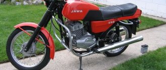
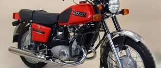
In 1970, the IZH Planet 3 model appeared in the production program of the Izhevsk Motor Plant.
Unlike its predecessor with the index “2,” the motorcycle received a new shaped gas tank, a more powerful engine and direction indicators.
Motorcycle generator IZH 281.3701
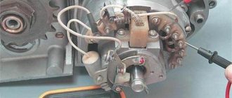
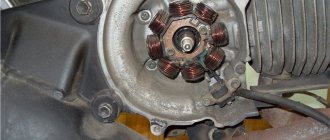
On IZH motorcycles starting from the fourth Planet, an alternating current generator 281.3701 is installed, which is a modern three-phase electric source of electricity. This source is used to power electrical lighting, alarm, and ignition devices. Together with the rectifier, the BPV-14-10 regulator recharges the battery. The generator consists of two parts, a stator and a rotor.
. Converting the generator from 6 to 12 volts.
. Converting the generator from 6 to 12 volts.
Message Reset » 03 Aug 2005, 17:37
Don’t be afraid, I won’t suggest nonsense like “rewind the windings.” I will ask, because the forum is silent on this matter. So, there is a six-volt motorbike. I want 12 volts for obvious reasons. But for some reason I don’t have the slightest desire to sharpen the washer. If only because there is no material and generally known hemorrhoids. And here an idea arises: buy 12-volt stator windings and a rotor and install them into the housing from a 6-volt generator, flavoring everything with a brush assembly from a Lada (yes, even from an Izh). But a number of questions immediately arise: 1. Are the rotors and housings (inner diameter) of the generators the same diameter? 2. Are the cores of the stator windings the same, incl. by fastening, by the height and shape of the part where the wire is wound on them? 3. Is it possible to grind the rotor in case of minor discrepancies in diameters? Will this not affect the power of the equipment? 4. Well, in general, can the one who held both generators in his hands have anything valuable to say about transferring the filling of one into the other? I know it's a good idea
))
The plans include installing an optical BSZ (sold here with us) and plenty of driving without discharge with the ability to safely keep low revs.
/added 08/04/05/ I went to the spare parts store (I thought I just wouldn’t have time to get there within 5 days, that’s why I opened the topic). Alteration is not possible, at least with little cost. The diameter of the 6-volt generator is much smaller, the windings are completely different. In short, I’ll buy a zafftra adapter and install a 12-volt one. I’ll write an article about installing an optical BSZ if anything useful comes of it. The topic can be closed.
Re: . Converting the generator from 6 to 12 volts.
Posted by HP » 06 Aug 2005, 16:05
Reset wrote: Don’t be afraid, I won’t suggest nonsense like “rewind the windings.” I will ask, because the forum is silent on this matter. So, there is a six-volt motorbike. I want 12 volts for obvious reasons. But for some reason I don’t have the slightest desire to sharpen the washer. If only because there is no material and generally known hemorrhoids. And here an idea arises: buy 12-volt stator windings and a rotor and install them into the housing from a 6-volt generator, flavoring everything with a brush assembly from a Lada (yes, even from an Izh). But a number of questions immediately arise: 1. Are the rotors and housings (inner diameter) of the generators the same diameter? 2. Are the cores of the stator windings the same, incl. by fastening, by the height and shape of the part where the wire is wound on them? 3. Is it possible to grind the rotor in case of minor discrepancies in diameters? Will this not affect the power of the equipment? 4. Well, in general, can the one who held both generators in his hands have anything valuable to say about transferring the filling of one into the other? I know it's a good idea
))
Generator stator 281.3701 for IZH motorcycles
The stator is installed on the right half of the engine crankcase and secured with three bolts. The frame is made of special sheet steel. It has 18 tooth-shaped places for winding phase windings. The phase winding is made of one solid wire with a diameter of 0.9 mm and is wound on six teeth. Each tooth has 20 turns of copper wire wound around it. There are six teeth in total on the winding, so 120 turns are wound. There are three such windings. The connection of the windings is made with a star. The terminals of the phase windings are connected to the terminals of the comb.
The generator stator is covered with an aluminum alloy cover. There are special places on the cover and threaded holes where the carbon brush holder is installed. A breaker with a capacitor to produce a spark. Special comb for connecting wires.
Stages of electrical equipment modification
The entire procedure for switching to a battery-free circuit comes down to:
- Replacement of components for 12 volt equipment;
- Remaking the generator, and sometimes borrowing it from another model;
- Replacing lamps from 6V to 12V.
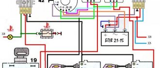
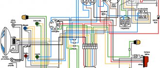
For reference: the wiring diagram on IZH Planet 3 does not change significantly - only the circuits of the generator, coil and voltage regulator relay are replaced.
Generator
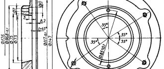
The main difficulty in altering the generator lies in the manufacture of a special intermediate ring. This requires the help of a turner - the ring is turned on a lathe.
- Two 6 mm holes are drilled to allow the ring to be secured on the right half of the crankcase;
- To attach the generator to the ring, three M5s are drilled;
- A segment is cut out of the ring to facilitate installation under the partition of the right half of the crankcase;
- Cutouts for the crankcase cover bosses are made on the right and bottom.
The numbers on the diagram indicate:
- Carter - right half;
- Power unit crankshaft;
- Intermediate flange mounting screws;
- The intermediate flange itself;
- Conical bushing made of sheet metal (S 0.8 mm);
- Generator stator;
- M5 screws for mounting the generator;
- Generator rotor;
- Rotation sensor;
- Rotor mounting bolt.
Generator rotor 281.3701
The generator rotor 1 is located inside the stator. It is installed on the crankshaft using bolt 3 and key 5. An excitation winding 6 is wound on the rotor core with a copper wire with a diameter of 0.56 mm, 600 turns are made. The winding resistance is approximately 6.4 ohms. For contact with the winding, two copper rings 2 and carbon brushes are used. They perform the work of a current collector.
How to remove the generator rotor 281.3701
The breaker cam 4 is installed in one position on the rotor shaft in a special socket and secured with a mounting bolt 3. Under this cam there is a thread that is intended for removing the rotor from the crankshaft. To remove the rotor, you need to screw the screw from the chain disassembly device into the thread. The device is located in the motorcycle tool. If there is no screw, you can use a regular bolt with an M10 thread. The only condition for the thread must be at least 70 mm. Turn until the screw rests on the crankshaft. Then we apply more force to tighten it, and the rotor is removed from the shaft.
Generator care
Comes down to visual inspection and cleaning.
First of all, you need to pay attention to parts subject to wear. The carbon brushes of the current collector wear out faster than other parts. They require regular inspection and are replaced if worn. The slip rings of the slip ring must be kept clean. You cannot clean it with sandpaper or needle files. You can use the finest glass sandpaper.
The breaker contacts are periodically checked for the gap value specified in the instructions. For Planet 4 the gap is 0.4 - 0.6 mm. In case of burning, the contacts are leveled and then polished to a mirror finish.
Generator faults
Here we will consider only the malfunctions of the generator IZH 281.1701. First, let's write down the symptoms of a motorcycle malfunction. The next entry will be a possible generator malfunction.
1. The indicator lamp in the instrument panel does not light up. — The generator brushes began to move poorly, the contact between the brush and the ring was lost, or the wire at the brush broke.
2. The control light is on all the time. — The excitation winding has failed. The generator is not working.
3. Engine light is low at medium speeds. — A short circuit occurred in the phase windings of the generator stator.
4. Interruptions in engine operation. The spark is not constant. — Incorrect contact adjustment. The capacitor has failed.
5. Engine power has dropped. — The adjustment in the contacts has gone wrong. The ignition is not installed correctly.
6. The engine does not start or stalls quickly. — Conductive debris has entered the contacts. The capacitor may be faulty.
Source
To watch online, click on the video ⤵
How to remove a generator from an IZH motorcycle. Read more
How to replace the generator and armature of an Izh motorcycleRead more
How to quickly remove the anchor. Izh Planet. Izh JupiterMore details
How to remove a generator armatureRead more
IZH Planet 5, no charging due to the brushRead more
How to remove the anchor of the Izh Jupiter Planet generatorRead more
How to quickly and easily remove the armature of a Java 634 motorcycle generator?Read more
#282: Assembling a generator for the Planet 5 engineRead more
Guide to removing the IZH rotorMore details
Generator IZH Planet 5 how to connect [2021] / how to install generator IZH Planet 5 [2021]Read more
Removing and installing the rotor. Replacing a generator on a motorcycle Minsk. Chinese generator testRead more
remove the generator rotor from IZ Jupiter\PlanetRead more
Izh 5 1 Method for checking whether a motorcycle generator is working or not. Read more
#343: Dismantling the old power unit Planet 5 – Generator (part 2)Read more
How to remove the armature stator of the generator jawa 634 638 350 360 old woman Izh Jupiter Izh PlanetRead more
Converting the electrical circuit to work without a battery
Unlike cars that have a closed engine and electrical wiring, parts of the IZH Planet 3 motorcycle are more susceptible to external factors than others:
- Rain and snow;
- Direct sunlight;
- Mechanical damage from bushes.
The owners are especially troubled by the standard battery, which is also quite difficult to maintain (see also the Ural motorcycle wiring diagram).
The factory instructions provide:
- The need to constantly check the electrolyte level in banks, because when the motorcycle tilts, it inevitably leaks out;
- The need to constantly check the electrolyte density. This forces motorcycle owners to have a hydrometer, distilled water and hydrochloric acid on hand to restore the required density with their own hands.
Alteration of the power supply system of motorcycles IZH-Jupiter 4.5 and IZH-Planet 4.5
Redesign of the power supply system for IZH-Jupiter and IZH-Planet motorcycles.
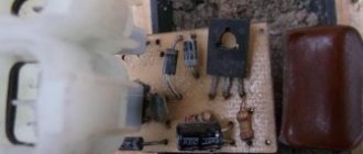
In the practice of an auto electrician, sometimes there are cases that the police call “hanging”. I hope there is no need to explain what this is. These, of course, in my practice include the power supply system for IZH-Jupiter and IZH-Planet motorcycles from the 4th to the 7th series. It seems to be a simple system, but it is not a system, it is a fragment of the Soviet era. In my opinion, it takes very little time to diagnose a malfunction when “charging” disappears: in 90% of cases it is a failure of the rectifier-voltage regulator unit. As a rule, it breaks through thyristors, which act as key elements in the excitation winding circuit. The remaining 10% is mainly wear and tear on the graphite brushes of the field winding circuit. The rest, in principle, is “exotic” :)) like a break or breakdown. At the same time, after the repair, the motorcyclist, being warned that it is impossible to check the operability of the repaired unit by disconnecting the battery, “secretly” from the master, still checks for the presence of “charging”, which in about half of the cases leads to a repeated call either to “ complaints" regarding the poor quality of the work done. After numerous attempts to change the situation radically, the following scheme emerged (see Fig. 1. 3):
Fig.1. Charging option with integral.
Fig.2. Charging option with PP
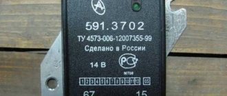
I thought, how, exactly, in terms of energy supply, does a motorcycle differ from a car? Yes, practically nothing! The same alternator (alternating current generator), rectifier, voltage regulator, battery. But practice has shown that there are differences, and quite significant ones: A motorcycle, due to the fact that the generator “sits” on the shaft of a two-stroke engine, has a very uneven oscillogram of the generator operation, because it is a two-stroke engine, and also with a chain drive and, practically, Without a flywheel, it rotates very unevenly. This is what leads to the fact that the operation of many voltage regulators is completely disrupted, for example, PP-362B1 (Fig. 4),
which is used in domestic trucks and tractors, and is also found on many relatively old domestic passenger cars, as an inexpensive and reliable substitute for standard voltage regulators. I dare to say that I always have at least one of these in stock, since in many cases, in terms of price-quality ratio, there is simply no alternative to it in our area when repairing the above-mentioned category of transport, but it can be repaired easily and cheaply: the case is opened, the transistors are replaced KT816 and KT837. And now a logical question: why have I been dwelling on the topic of this relay - regulator for so long? And the answer is very simple: this is one of the first domestic transistor voltage regulators, which uses a trigger circuit for controlling key transistors. And many later models of regulators, despite external differences in the form of other boards, cases and sizes, copy precisely its circuit design, since the PP-362B1 regulator is indeed very successful. But the motorcycle generator produces pulses that completely disrupt the operation of the composite dinistor on complementary transistors KT315, KT361. As a result, the regulator does not affect the zero charging current in any way :))) An attempt was made to introduce capacitors into the circuit, connecting them in parallel with the rectifier diodes, but no significant difference was noticed. Then the search began for another regulator. During the search, preference was given to the minimum price with maximum node performance. As a result, the following units performed well: (1) Y112V1 integrated unit (the so-called “chocolate box”) (Fig. 5)
and strictly still Soviet, or one of those found in new tractor generators, which, by the way, are quite expensive. A distinctive feature of what is needed is the presence of a small hole on the top of the IRN cover, through which the IRN is filled with compound. And those who “sunbathe in store windows in negligee” burn out immediately: ((. (2)Also, the so-called “pill” (Fig. 6),
included in the brush holder of the VAZ-2108 -09 -099 generator. In stores they call it a brush holder. Moreover, preferably, manufactured by BOSCH or from a Mercedes generator. Our regulator comes last. (3) Also, oddly enough, some cheap regulators, like “chocolate bars,” even with SMD mounting under plexiglass, only designed for separate installation. These are regulators PP-362B1-03 (Fig. 7)
When they fell into my hands, there were no markings on them, except for the letters “VZ”, “Sh” and “M”, and I involuntarily remembered the cat Matroskin and his documents (whiskers, paws and tail). But if they work properly, they work. After all the modifications, the voltage in the motorcycle’s on-board network becomes truly stable, which has a positive effect on the operation of the motorcycle as a whole: easy starting even on a discharged battery, relatively rarely burnt ignition contacts and, as a result, slightly lower fuel consumption, powerful light. And you have to spend less time on maintenance. At one time, a lot was said about the introduction of a relay into the power supply circuit of the ignition coils on the pages of the magazines “Behind the Wheel” and “Moto”. Therefore, I will not particularly focus your attention on this, but those who wish can check the usefulness of the relay this way: first you need to measure the voltage at the terminals of the motorcycle battery and compare it with what reaches the ignition coils. Usually the ratios are: 12.13 v on the battery and 8.9 v on the coils! And this is with the standard, factory scheme after a year or two of operation! No wonder the motorcycle is so reluctant to start! Motorcyclists often solve this problem this way: install 6 V ignition coils on their motorcycles. Then the bike starts. And if you install a relay, then it is possible to start from 6 v, and even from 4 v, like one of the samples I converted! Another weak point of the standard motorcycle electrical circuit is that ALL charging current goes from the generator to the battery through the ignition switch! And here is the switching of light circuits! It’s no wonder why the ignition switches of domestic motorcycles fail so often! Could this problem really not have been solved, but not created at all?
Tuning the Izh motorcycle. We are converting Izh to a 12V ignition system.
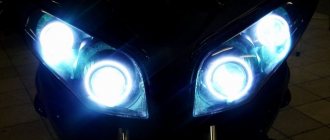
Despite the fact that it is already the 21st century, there are still many motorcycles left with a 6-volt ignition system.
A weak headlight makes driving in the dark completely unsafe. Spare parts for the 6-volt ignition system have not been produced for a long time. Finding a replacement for a failed generator or charge relay is almost impossible, although the motorcycle itself can still serve its owner well. To switch to 12 volts, you need to prepare the following things: a 12V battery, a 12V generator, a 12V charge relay, a piece of wiring from the generator to the charge relay from an Izh motorcycle with a 12-volt ignition system, ignition coils also need 12V, all the lights and turn relays also need to be replaced with 12 V. It is also necessary to make an adapter plate.
After all the necessary accessories are available, we begin dismantling the old generator and charge relay. We also change the ignition coils to 12 V. We install the adapter plate into the mounting points of the old generator on the right crankcase cover. We install a new anchor on the shaft. We attach the new generator to the adapter plate.
We install the new charge relay in place of the old one; if necessary, we alter the points at which the relay is attached to the motorcycle frame under the seat.
We connect the charge relay to the generator using a bundle of existing wires. We carefully isolate everything. We leave the wires from the contacts from the old wiring; we connect them to the negatives of the ignition coils. We connect a new battery, check the spark on the spark plugs by opening the contacts. We set the ignition timing as usual and start! We measure the voltage in the motorcycle network with a tester. With a correctly assembled circuit, the voltage in a running engine should be about 14 - 14.5V.
Now our motorcycle has the opportunity to install BSZ instead of contacts, which we could not afford before, but this is another topic. Good luck to everyone on the roads!
The editors of the magazine thank Dmitry Khoreshko for kindly providing materials for the article.
If you have something to share with readers and would like to publish your story or photo report about your travels on our website, please send the materials to:
Source