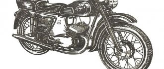
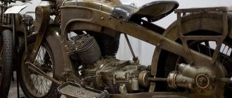
Engine IZH Jupiter
In 1961, an Izhevsk motorcycle called Jupiter was released. A new family of IZH Jupiter has appeared. The design is similar to the IZH-56 motorcycle produced earlier. Its significant difference is the installation of a two-cylinder engine. In addition, some changes have been made to the clutch, gear shift device and electrical equipment. At the front of the crankcase there are two crank chambers, and at the rear there is a gearbox. The crank chambers are closed with covers and each of them contains crankshafts on ball bearings, which are protected from axial displacement by retaining rings. The crankshaft axle shafts are sealed with oil seals. Under the left crankcase cover mounted on a gasket, the front chain drive, clutch and trigger mechanism are located. The crankshafts are connected to each other by an external flywheel. The generator rotor and the breaker cam are installed on the axle cone of the right crankshaft. The generator housing is mounted on the crankcase. The engine pistons are connected to the crankshaft connecting rods using piston pins, which are protected from axial displacement by retaining rings. The engine cylinders have aluminum jackets and cast iron liners. The cylinder heads are made of aluminum alloy and are attached together with the cylinders to the crankcase with studs.
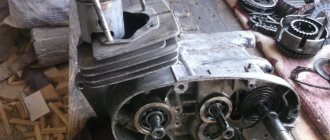
Engine part of IZH Jupiter
The motor part of the engine consists of a cylinder-piston group, a crank mechanism and a crankcase group.
Motor part of IZH Jupiter: 1 – generator cover; 2 – right crankcase cover; 3 – generator; 4 – right seal with cover; 5 – right crankshaft; 6 – right half of the crankcase; 7 – flywheel; 8 – crankshaft seal; 9 – crank chamber cover; 10 – left crankshaft; 11 – left seal; 12 – left half of the crankcase; 13 – crankshaft sprocket; 14 – left crankcase cover; 15 – cylinder; 16 – cylinder head; 17 – piston; 18 – spark plug; 19 – connecting rod; 20 – hairpin.
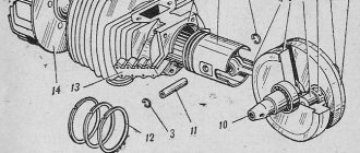
Engine parts IZH Jupiter
Engine parts: 1 – cylinder pipe; 2 – cylinder gasket; 3 – left cylinder; 4 – hairpin; 5 – left cylinder head; 6, 12 – washers; 7 – nuts; 8 – retaining ring; 9 – piston; 10 – piston ring; 11 – left cheek of the crankshaft; 13 – connecting rod; 14 – right cheek of the crankshaft; 15 – flywheel; 16 – bushing; 17 – piston pin; 18 – crankshaft; 33 – flywheel mounting bolt; 34 – crank pin; 35 – needle bearing.
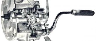
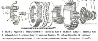
Clutch IZ Jupiter
Located on the left side of the engine in an oil bath. Closed with a lid with a gasket to prevent oil leakage. The main thing that can be said when assembling the coupling. Some conditions need to be met. The first compression spring nuts should protrude 3.5 - 4.0 mm above the caps. This will save the disks from distortion. Tighten the second adjusting screw until it stops. Then loosen by 1/4. 1/2 turn. Essentially this is a clutch adjustment.
Details of the Izh Jupiter clutch: 19 – bracket with lever; 20 – outer clutch drum; 21 – pusher; 22 – ball; 23 – thrust rod; 24 – inner clutch drum; 25 – clutch drive disk; 26 – driven disk; 27 – pressure disk; 28 — cap; 29 – spring; 30 – shaped nut; 31 – adjusting screw; 32 – nut.
IZ Jupiter clutch diagram
The clutch of the IZH-Jupiter motorcycle differs from the clutch of the IZH-56 motorcycle by the installation of a ball bearing and an adjusting screw 31 with a lock nut 32.
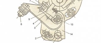
IZ Jupiter trigger mechanism
The starting mechanism is designed to start the engine. Has no adjustments. The parts are simply assembled in the right position and that’s it. During operation, worn parts are replaced with new ones. The gears and sector are the first to fail - inspect the teeth.
Starting mechanism of the IZH Jupiter motorcycle: 1 - washer; 2 — trigger pedal; 3 - roller; 4 — pedal axis; 5 - ball; 6 — clamp spring; 7 - clamp; 8 - bolt; 9 — reflector; 10 - cuff; 11 — kickstarter shaft; 12 - sector; 13 - spring; 14 — washer; 15 - ring; 16 — washer; 17 — spring; 18 - gear.
Gear shift mechanism IZ Jupiter
It is located inside the gearbox and the control lever is on the left side of the engine. It has changed the drive device of the shift sector and forks, which operate directly on the worm shaft. If the switch does not work properly. Disassemble the engine and wash all switching parts and check for wear and chips. Replace faulty ones.
IZ Jupiter gear shift mechanism: 4 – shift pedal; 25 – spring of the gear shift mechanism; 26 – gear shift sector; 27 – mechanism leash; 28 – shaft; 32 – worm shaft; 33 – fork for switching second and fourth gears; 34 – fork for shifting first and third gears; 36 – clamp spring; 37 – neutral contact post; 38 – neutral contact flag; 39 – switching anchor.
Gearbox IZH-Jupiter
The gearbox of the IZH-Jupiter motorcycle on the IZH-Yu motorcycle is the same as on the IZH-56 motorcycle and differs only in the design of the switching mechanism. Basic care is checking the oil and replacing it in a timely manner.
IZ Jupiter gearbox diagram: 1 – input shaft; 2 – secondary shaft; 3 – intermediate shaft; 4 – support ball bearings of the shafts; 5 – roller bearing of the secondary shaft; 6 – gearbox gears; 7 – secondary shaft oil seal; 8 – asterisk.
IZ Jupiter engine diagram
Diagram of the engine block with gearbox, clutch and generator: 1 – spark plug; 2 – cylinder head; 3 – cylinder; 5 – piston; 6 – piston ring; 7 – bypass channel; 8 – piston pin; 9 – bushing of the upper head of the connecting rod; 10 – connecting rod; 11 – left crank chamber cover; 12 – drive sprocket; 13 – ball bearing; 14 – oil seal; 15 – left crankshaft axle shaft; 16 – roller bearing of the lower head of the connecting rod; 17 – crank pin; 18 – clutch spring; 19 – hatch cover; 20 – clutch adjusting screw; 21 – clutch pressure plate; 22 – inner drum; 23 – gear shift pedal; 24 – trigger pedal; 25 – left crankcase cover; 26 – clutch discs; 27 – outer clutch drum; 28 – trigger mechanism sector; 29 – spring; 30 – trigger gear; 31 – ball bearing; 32 – left half of the crankcase; 33 – gear shift fork; 34 – gear shift roller; 35 – gear shift sector; 36 – gear shift mechanism roller; 37 – fastening pin; 38 – right half of the crankcase; 39 – right cylinder head; 40 – right cylinder; 41 – flywheel; 42 – right crank chamber cover; 43 – cylinder gasket; 44 – right oil seal; 45 – generator; 46 – right crankshaft axis; 47 – right crankcase cover; 48 – generator cover; 59 – breaker cam; 50 – central anchor mounting bolt; 51 – asterisk; 52 – oil seal; 53 – roller bearing; 54 – secondary shaft; 55 – oil seal; 56 – input shaft; 57 – clutch release rod; 58 – clutch release lever; 59 – sprocket mounting nut; 60 and 61 – gearbox gears; 62 – clutch cable cam; 63 – clutch cam; 64 – spring.
Motorcycle engine diagram Izh Planet 5
Hail, gentlemen of mechanics and bikers! Welcome to the repair section All about motorcycles!
Motorcycle diagrams contain drawings of engines, electrical equipment (wiring) and other components of two- and three-wheelers with all the necessary decodings.
Today we will look at a schematic representation of the engine of the Soviet motorcycle Izh Planet 5, which is considered one of the most successful developments from domestic transport mechanics.
The reliability of this engine can only be compared with boxer engines, as well as the power unit of the previous single-cylinder model from IzhMoto.
1) Spark plug. 2) Motorcycle cylinder head, 3) Motorcycle cylinder. 4) Bike cylinder piston. 5) Piston ring. 6) Piston pin. 7) Izh Planet engine crankcase. Bearing lubrication channel.
9) Roller bearing. 10) Left motor oil seal. 11) Left cover. 12) Motor circuit. 13) Motor ball bearing. 14) Crankshaft star. 15) Outer clutch drum. 16) Clutch disc. 17) Internal clutch drum. 18) Pressure disk. 19) Spring. 20) Shaped nut. 21) Pusher. 22) Engine ball bearing. 23) Ratchet. 24) Gearbox shift lever. 25) Start lever. 26) Starting system shaft. 27) Gearbox shaft. 28) Launch system sector. 29) Spring. 30) Gearbox gears. 31) Gearbox gears. 32) Gearbox gears. 33) Gearbox. 34) Thrust mechanism. 35) Gearbox shaft. 36) Gearbox cover. 37) Installation sleeve. 38) Right cover. 39) Gearbox gears. 40) Gearbox gears. 41) Intermediate shaft. 42) Gearbox gears. 43) Motor ball bearing. 44) Roller bearing of the Izh Planet 5 engine. 45) Secondary shaft. 46) Primary shaft. 47) Clutch adjustment screw. 48) Worm gear ball. 49) Worm mechanism of the clutch system. 50) Nut cap for the secondary shaft. 51) Crankcase oil seal. 52) Star. 53) Moto generator. 54) Right crankcase oil seal. 55) Engine roller bearing. 56) Crankcase gasket. 57) Crankshaft. 58) Bypass channel. 59) Exhaust system window. 60) Motorcycle decompressor.
Detailed diagram of the Izh Planet 5 engine crankcase:
1) Five-fiber washer. 2) Screw. 3) Screw. 4) Left crankcase cover. 5) Left crankcase cover gasket. 6) Filler plug. 7) Fourteen fiber washer. Screw. 9) Stopper bar. 10) Adjusting washer. 11) Adjusting washer. 12) Adjusting washer. 13) Ball bearing of the Izh Planet engine. 14) Ball bearing of the Izh Planet engine. 15) Drain plug. 16) Gasket. 17) Cylinder mounting stud. 18) Puck. 19) Gadget. 20) Breather. 21) Contact for the neutral gear identification mechanism. 22) Left half of the motorcycle crankcase. 23) Crankcase bushing. 24) Right half of the motorcycle crankcase. 25) Gaskets. 26) Gearbox cover. 27) Motor mounting sleeve. 28) Plug. 29) Plug. 30) Retaining ring. 31) Right cover. 32) Screw. 33) Generator cover. 34) Cover. 35) Installation ring. 36) Screw. 37) Screw. 38) Screw. 39) Screw. 40) Installation sleeve. 41) Washer. 42) Plug. 43) Screw. 44) Cylindrical pin.
Electrical equipment of the IZH Jupiter motorcycle
The electrical equipment of the IZH Jupiter motorcycle differs only in the installation of the G-36M2 generator.
Electrical diagram of the IZH Jupiter motorcycle:
1 — rear light; 2 — neutral lamp switch; 3 - central switch; 4 — neutral indicator lamp; 5 — speedometer lighting lamps; 6 - main lamp; 7 — parking light lamp; 8 — light switch; 9 — sound signal; 10 — brake light switch; 11 - candle; 12 — control lamp; 13 - fuse; 14 - battery; 15 — relay-regulator; 16 - generator; 17 - capacitor; 18 - breaker; 19 - ignition coil.
Gear diagram of the engine of the IZH Planet 5 motorcycle:
1) Gearbox input shaft. 2) Gearbox second gear. 3) Thrust washer. 4) Installation ring. 5) Gear of the second and fourth gears of the gearbox. 6) The assembled gearbox input shaft. 7) Puck. Gearbox secondary shaft with bearing. 9) Gearbox secondary shaft star. 10) Lock washer. 11) Secondary gearbox shaft nut. 12) Cap of the secondary gearbox shaft nut. 13) Ring. 14) Gearbox intermediate shaft. 15) Gearbox third gear. 16) Installation ring. 17) Gear of the first and third gears of the gearbox. 18) Gear of the first and third gears of the gearbox.
- Back
- Forward
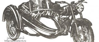
Motorcycle IZH Jupiter with sidecar
Motorcycle IZH Jupiter K with an increased gear ratio in reverse gear. The drive sprocket is installed with a smaller diameter and fewer teeth. The presence of a stroller forced the manufacturer to increase the torque, but reduce the speed to 80 km/h.
The side trailer of the IZ Jupiter K motorcycle is designed for a load capacity of 100 kg. The frame is made of pipes. The body is metal. The wheel suspension is of torsion bar type, spring type. There is no brake on the side trailer wheel.
Electrical diagram of the IZH Jupiter motorcycle with a sidecar.
No major changes have been made to the electrical circuit. Provision is made for installing a marker light 20 on a side trailer. The generator produces 45 watts of power and a voltage of 6 volts. There is a battery and a voltage regulator.