CRANKSHAFT OF MOTORCYCLE ENGINES “URAL”, “DNEPR”
The crankshaft of the MT 10-32 engine is cast from high-strength cast iron. The shaft rests on two bearings (Fig. 2.4). The shaft elbows are located in the same plane at an angle of 180°. The nominal diameter of the main journals is 45±0.008 mm, the connecting rod 48±0.025 mm.
The connecting rod journals are hollow. Their cavities are closed with threaded plugs and cored. The crankshaft cheeks adjacent to the main journals have a balancing system.
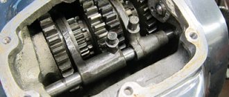
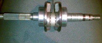
At the front end of the crankshaft, drive gear 4 of the camshaft and a centrifuge are installed on segment keys. The rear end of the shaft is conical. A flywheel 22 is installed on it, secured with a central bolt 29. After tightening, the bolt is secured with a washer 27. To ensure that the engine runs without vibration, the crankshaft and flywheel are balanced. The crankshafts of the K-750M and M67-36 engines are assembled from individual parts using special technology and are non-separable. Such shafts can only be disassembled and assembled using special tools. The crankshaft (Fig. 2.25) consists of two axles (front 6 and rear 4) with main journals and counterweights, a middle cheek 2 and crank pins 3. All parts are connected to each other using a press fit. Oil traps are screwed to the outer sides of the front and rear axle. There are blind holes in the fingers and
radial channels for supplying oil to roller bearing 5 of the lower head of connecting rod 1. A gas distributor drive gear is installed on the journal of the front axle, and a flywheel is mounted on a key on the conical part of the rear axle.
The front and rear crankshaft journals and the middle cheek of the K-750M engine are made of 45 steel, and the M67-36 engine is made of alloy steel.
To ensure assembly accuracy and load uniformity, the rollers are divided into groups depending on the size of the outer diameter (Table 2.6).
The inner ring of the roller connecting rod bearing is the surface of the crankshaft pin. Before assembling the crankshaft, the connecting rod bearings are assembled.
Connecting rods, crank pins and rollers are manufactured with high precision and then sorted and labeled. The fingers are marked by the inner diameter, the rollers by the outer diameter, and then assembled (Table 2.6).
For assembled connecting rod bearings, the clearance in the assembled bearing should be in the range of 0.010 - 0.024 mm for the K-750M engine and 0.010 - 0.012 mm for the M67-36 engine.
Rice. 2.25. K-750 engine crankshaft assembly: 1 — connecting rod; 2 - middle cheek; 3 — crank pin; 4 — rear axle, 5 — roller bearing of the lower head of the connecting rod; 6 - front axle
content .. 11 12 15 ..
Dismantling and reassembling the front fork on a Ural motorcycle.
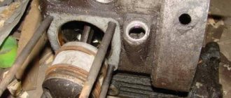
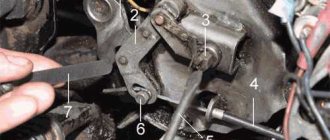
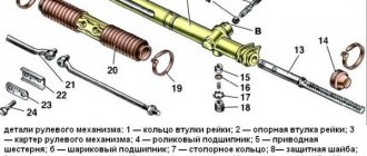
To disassemble the stay (Fig. 61), unscrew the nut 17 securing the fork leg tube to the yoke 19, slightly pull the shock absorber rod upward, loosen the lock nut of the rod and unscrew the nut from the shock absorber rod. Insert the front axle into the tip of the fork leg and use a ring wrench to unscrew the oil seal housing assembly 24. Remove the fork leg tip down from the fork leg tube along with the shock absorber 4 and spring 7. Remove the spring ring 12 securing the lower bushing of the fork leg pipe 9, the lower and upper bushings fork leg pipes and oil seal assembly. Unscrew the nut of the bridge coupling bolt 16 by 2.3 turns and remove the fork leg tube downwards (to make it easier, screw the tightening nut onto the end of the fork leg tube by four to five threads and knock the pipe out of the traverse cone with light blows of a rubber hammer).
To disassemble the shock absorber, unscrew the bolt securing the shock absorber housing cone 4 at the bottom of the fork stay, remove the shock absorber washer 15 and the sealing washer 18 under the bolt, remove the shock absorber 4 assembled with the spring, and unscrew the upper nut on the shock absorber rod and spring and the upper tip. Then remove the spring, unscrew the shock absorber tube nut and remove rod 5.
When repaired, the first fork blade may have the following defects: .
- dents on the pipe - straighten the pipe until the defect is eliminated;
- failure of threads on a pipe of more than two threads - replace the pipe or repair it, grind off the threads, scald the surface, grind and cut threads of normal size M48X1.5;
- wear of the surface of the hole in the fork leg tip pipe for the lower bushing to a diameter of more than 42.2 mm (for motorcycles “Dnepr”, “Ural” M-66 and M-67-26) and more than 37.2 mm (for motorcycles “Ural” M-62 and M-63) - process the hole to a repair size of 42.5+0-09 mm for the repair sleeve;
- failure of the threads of holes in the tip of more than two threads - drill holes, weld, drill and cut threads of normal size, respectively M18X1.5 (left) and MB, weld cracks; if the base lugs at the left tip of the fork blade break off, weld them on and process them to normal size.
During repairs, the steering column rod with bridge assembly may have the following defects:
- cracks, broken rod or bridge of any size and location - replace the part;
- bending of the steering column bridge at the transition points to the fork leg mounting hubs is more than 0.02 mm over a length of 100 mm - straighten the bridge until the bending is eliminated;
- wear of the bridge journal surface under the angular contact ball bearing to a diameter of less than 33.95 mm - chrome plate the surface and grind it to the normal size of 34 mm. It is allowed to weld and process the neck to normal size;
- weakening of the fit of the steering column rod - if the surface of the rod is worn to a diameter of less than 28.100 mm, its surface should be chromed and ground to a normal size of 28 mm or repair dimensions of 28.2; 28.4 mm (repair dimensions are allowed only when eliminating the defect by welding the surface). If the surface of the bridge hole is worn to a diameter of more than 28.05 mm, weld the surface and process it to the normal hole size of 28 mm. It is allowed to machine the hole to repair dimensions of 28.2 and 28.4 mm for the steering column repair rod;
- wear of the bridge pin under the steering shock absorber washer to a diameter of less than 11.7 mm - replace the pin;
- If the threads on the rod are broken by more than two threads, replace the rod;
- weakening of the fit of the pins in the holes of the bridge - if the threads in the holes of more than two threads are broken, replace the defective pin with a new one;
- If more than two threads are broken, drill a hole and cut a thread of repair size M10X1 for the repair pin.
During repairs, the right casing assembly may have the following defects:
- broken front brake cable holder, shield mounting ear, turn signal mounting bracket - replace the defective part;
- cracks in the headlight bracket or housing stocking - weld the cracks and clean them flush with the base metal;
- dents more than 1.5 mm deep - straighten the casing until the unacceptable dents are eliminated;
- crushing and crumbling of more than four teeth of the headlight bracket washers/ - replace the defective washer.
During repairs, the front wheel guard assembly may have cracks and dents - weld the cracks and clean them, remove the dents. For Ural motorcycles M-63, M-66 and M-67-36, if the rubber part of the shield breaks, it is allowed to apply a patch to the glue on the inside.
The fork leg tube is made of steel pipes (steel 35) and has a hardness of HB 200-240. During repairs it may have the following defects:
- the bent of the fork leg tube is more than acceptable (mutual beating of the surfaces is allowed no more than 0.1 mm)—straighten the tube until the bent is eliminated;
- wear of the pipe surface to a diameter of less than 36.75 mm - chrome the surface and grind it to the normal pipe size of 361 mm, for the Ural M-62 and M-63 motorcycles the normal pipe size is 35 mm;
- wear of the conical surface under the traverse (it is permissible for the conical gauge (ring) to be no more than 30.95 mm long) - scald the surface and process it to the normal size of the cone;
- wear of the surface under the lower bushing to a diameter of less than 30.9 mm (only for Ural motorcycles M-62 and M-63) - chrome the surface and process it to the normal pipe size of 31 mm;
- failure of threads in a pipe of more than two threads - drill a hole, weld, bore and cut a thread of normal size M27±.5 mm.
The oil seal body is made of steel 35. During repair, it may have the following defects:
- cracks of any size and location - replace the housing;
- thread failure of more than three threads - replace the body;
- wear of the hole surface to a diameter of more than 4.7 mm—weld the hole and drill to a normal size of 4 mm (it is allowed to drill new holes in the spaces between the old ones, which are welded and cleaned).
The traverse is made of steel 35 or 45. During repairs it may have defects:
- cracks of any size - replace the traverse;
- bent more than 0.2 mm over a length of 100 mm - straighten the traverse until the bent is eliminated;
- wear of the surface of the hole for the bearing nut to a diameter of more than 32.15 mm—boil the hole and process it to the normal size of 32+0-1 mm;
- wear of the conical surface under the fork leg tube, sinking of the conical gauge by more than 0.2 mm from the nominal position - scald the surface and process it to normal size.
When the surface of the hole in the shock absorber body tube for the piston and guide is worn to a diameter of more than 16.2 mm, the hole is machined to a repair size of 16.3 mm for the repair piston and repair guide. Repair parts are made of steel 35.
Assembly. Reassemble the front fork in reverse order. Before assembly, all parts are thoroughly washed in kerosene.
Particular attention is paid to the cleanliness of the internal cavities of pipes, tips, fork legs and cylinders. After preliminary assembly of the shock absorber body cone with the pipe, check the perpendicularity of the end of the cone relative to the tube. Non-perpendicularity is allowed no more than 0.15 mm over a length of 100 mm. If necessary, the end of the cone can be mechanically processed, and the length of the pipe assembled with the cone must be at least 202 mm. The gap between the shock absorber piston and the body tube should be 0.06...0.55 mm, between the lower shock absorber guide and the tube - 0.12...0.5 mm, and between the rod and the hole in the pipe nut - 0.35...0.7 mm. The rod nut is screwed onto the rod until it stops. In this case, the size from the end of the rod to the end of the nut must be at least 32 mm. Nominal dimensions, tolerances, clearances and tensions in the main mating parts when assembling the front fork are presented in Table 24.
After installing the rod with the piston and guide into the body pipe and installing the shock absorber pipe nut, the rod should move freely, without jamming. The gap between the upper bushing of the fork leg and the pipe should be 0.075...0.36 mm, between the lower bushing of the fork leg and the tip - 0.025...0.25 mm. Pipes assembled with bushings must move freely inside the mating tips assembled with shock absorbers and bushings (check before installing the seal assemblies). The gap between the tip of the upper spring and the nut should be 0.2.„0.5 mm. The seal assemblies are installed on the tips of the feathers on thickly grated red lead. When installing the oil seal housing onto the airfoil pipe, a mandrel is used. After assembly, check the fork legs for leaks under a pressure of 50 kPa for 10 s by immersing the forks in water. Air leakage at the connection points is not allowed. Do not add oil to the fork before testing. During the test, no more than two or three air bubbles are allowed to appear from under the seal. The permissible difference in the lengths of the left and right feathers is no more than 2.5 mm.
Before screwing the tightening nut securing the fork leg pipe into the yoke, screw a plug or screw to drain the oil. 135 cm3 of engine oil is poured into the fork leg pipe from above.
When tightening the tightening nut to ensure a tight fit of the cone connection in the fork crossmember, loosen the nut of the fork bridge coupling bolt and tighten it after tightening the tightening nut.
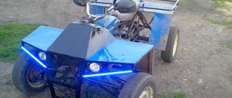
Tricycle from the Urals and VAZ-2101
When creating a cargo tricycle with your own hands from the Urals and parts of a VAZ-2101 car, the easiest thing will be to install a regular bridge and make a car suspension with shock absorbers from the Urals.
The bridge from the VAZ-2101 is turned over, after welding the differential. This is reflected in the handling - the steering wheel is quite difficult to turn, however, the trike's cross-country ability increases.
The driveshaft is shortened and welded to the fork on the final drive and connected to the axle through a rubber coupling. It is better to take the original Uralov clutch, in this case the transmission will be softer.
To avoid bending the cardan drive, you can move the engine to the left by 7-9 cm, or move the axle to the right or increase the wheelbase.
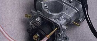
It is better to leave the engine as a whole unchanged, but instead of two carburetors, make one Chinese one. And for forced cooling, use an air filter from Izh.
Additionally, to cool the engine when operating in difficult conditions, you can install two fans and run them separately if necessary.
Pros and cons of the design
+ Simple and cheap transport;
+ The engine does not overheat.
- Can only go forward;
— Too much load on the axle with the front wheel;
— Goes too fast in first gear.
How to make a tricycle from a Ural and ZAZ-968 motorcycle
The front fork works like in the Urals, a lever system is used and the front axle is located between the transverse arms.
When creating a trike from the Urals and a ZAZ-968 car, the rear part remains practically unchanged, like a car. Only a muffler, oil cooler and air filter are added there. The gearbox and engine are also original to ZAZ. The engine is mounted as before, and the gearbox is placed on the left.
In general, there is not much to change.
DIY assembly steps
- At the very beginning, the rear axle is removed from the car.
- A beam is attached to the cut.
- Mufflers, an air filter, an oil cooler and pipes are installed on the rear wheel axle. If you use engines from the 90s, then all these elements will already be installed.
- A frame is being made that will be the basis of the tricycle, so it is necessary to make it strong and reliable.
- An extended front fork is manufactured by welding with shock absorbers attached to it. Lengthening occurs by replacing the fork rods with longer ones or by welding more tubes to the Ural fork.
- Welds the frame and rear axle of the car, forming a solid structure.
- The fork is connected to the frame by welding, just like with the rear axle of the ZAZ.
- After this, the seats, gas tank and other elements are attached.
- Finally, the new tricycle is painted and chromed.
Ural Hercules - factory Ural tricycle
The Irbit Motorcycle Plant has released a three-wheeled modification in its model range for transporting cargo up to 500 kg. The model is called “Hercules” and moves well both on city roads and off-road. The sides of the tricycle are also removable and this allows it not to be limited in the size of the cargo it transports. Hercules is a truck that does not require a category “C” license.
Technical characteristics of the Hercules tricycle:
- Dimensions: 335x150x115 cm
- Ground clearance: 185 mm
- Weight: 500 kg
- Fuel tank capacity: 19 l
- Maximum speed: 70 km/h
- Engine capacity: 750 cc
- Power: 45 hp
- Engine type: opposed 4-stroke with two cylinders
- Generator: 500 W
- Electrical: 12 V
- Transmission: 4-speed, with reverse gear
- Tires: 6.45 and 13 inches