A few years ago I made myself an ATS (automatic transfer switch) to work at the dacha using a generator. Now many IT workers are switching to remote work, working from their dachas, where the quality of power supply may be poor. Therefore, I decided to write about my experience of a homemade ATS on the ATmega8A microcontroller. If the topic is interesting, welcome to the cat, there will be a lot of letters and code.
About grounding
Before you do anything with electricity, you need to make sure there is a good grounding in your home.
You won’t be able to simply take and connect a regular household gasoline/diesel/gas generator to the electrical network at home. Precautions must be taken. The first is that your generator must be well grounded. Then you have a good chance of not getting an electric shock when the static from your favorite sweater penetrates the insulation of the generator winding. In general, you should not touch a running generator unnecessarily. It is worth remembering that the network is not always 220V. Switching on lines, lightning discharges in the distance, and static discharges produce such interference that short pulses of several kilovolts are not uncommon in the network. They combat this by installing arresters and surge protection devices at the entrance to the house, but this is a very rare practice in the Russian Federation. So let the spark go into the ground, and not through you - make good grounding throughout the house. Without this, you simply cannot do anything further!
About generators
By the way, many household gasoline generators have windings that are not connected to ground in any way.
And this is quite normal when you are powering one power tool from a generator. But when you need to connect the generator to the house, you need to make a neutral wire (N) and a phase wire (L). To do this, one of the terminals of the generator is grounded and from this grounding point two wires must be independently led into the house - one will be the neutral N, and the second will be the protective ground (PE). When choosing a generator, you need to pay attention to whether its output can be grounded; sometimes this is prohibited in the instructions for the generator, then such a generator will not suit you. Often on the Internet you can see diagrams for connecting a generator without grounding and separating the N and PE lines.
Don't do this, you'll live longer. Such schemes work well until the first unfortunate set of circumstances. Typical power supplies for modern electronic devices contain capacitors from lines L, N to ground. If N is not grounded at the generator, then due to these capacitors on line N there will be, if you're lucky, 110 volts relative to ground. By the way, many gas boilers stop working altogether in this mode. I already wrote above about the influence of statics without the presence of grounding.
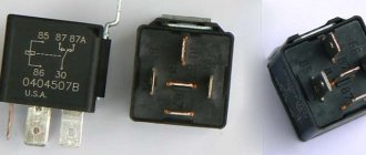
Regulator relay diagnostics
Voltage regulator failures can be determined by indirect signs. First of all, this is incorrect battery charging:
- overcharge - the electrolyte boils away, the acid solution gets on the body parts
- undercharging - the internal combustion engine does not start, the lamps are dimly lit
However, it is preferable to diagnose with instruments - a voltmeter or tester. Any deviation from the maximum voltage value of 14.5 V (in some cars the on-board network is designed for 14.8 V) at high speeds or the minimum value of 12.8 V at low speeds becomes the reason for replacing/repairing the regulator relay.
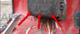
Built-in
Most often, the voltage regulator is integrated into the generator brushes, so a level inspection of this unit is necessary:
- After removing the protective cover and loosening the screws, the brush assembly is removed out
- When the brushes are worn out (less than 5 mm of their length remains), replacement must be carried out without fail.
- Generator diagnostics with a multimeter are carried out complete with a battery or charger
- The “negative” wire from the current source is closed to the corresponding regulator plate
- The “positive” wire from the charger or battery is connected to a similar relay connector
- the tester is set to voltmeter mode 0 - 20 V, the probes are placed on the brushes
- in the range of 12.8 - 14.5 V there should be voltage between the brushes
- when the voltage increases above 14.5 V, the voltmeter needle should be at zero
Rice. 22 Diagnostics of the built-in relay
In this case, instead of a voltmeter, you can use a lamp, which should light in the specified voltage range and go out when this characteristic increases above this value.
The wire that controls the tachometer (marked W only on relays for diesel engines) is tested with a multimeter in tester mode. It should have a resistance of about 10 ohms. If this value decreases, the wire is “broken” and should be replaced with a new one.
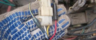
Remote
There are no differences in diagnostics for the remote relay, but it does not need to be removed from the generator housing. You can check the generator voltage regulator relay with the engine running, changing the speed from low to medium, then high. Simultaneously with the increase in speed, you need to turn on the high beams (at a minimum), the air conditioner, the monitor and other consumers (at a maximum).
Rice. 23 Diagnostics of remote voltage regulator
Thus, if necessary, the vehicle owner can replace the standard voltage regulator relay with a more modern modification of a built-in or remote type. Diagnostics of performance is available on your own with a regular car lamp.
If you have any questions, leave them in the comments below the article. We or our visitors will be happy to answer them
About AVR schemes
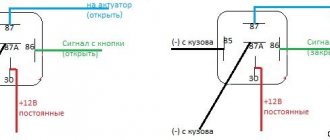
There are several different schemes for implementing ATS. Next I will write about the safest, from my point of view, single-phase ATS circuit. I do not advise economically making an ATS on one contactor or with switching only one phase wire. Only together with neutral.
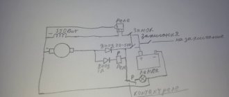
In the diagram shown, power from the network and from the generator is supplied through inputs 1 and 2. They are protected by paired circuit breakers. The switching and indication circuits are powered through additional circuit breakers. It can be seen that the relay coils are electrically interlocked. For the sake of simplicity, a microcontroller not shown in the diagram, which closes the circuits at the switching point TK1 or TK2, is responsible for turning on one or another input.
The fundamental point is the presence in the ATS of 2 interlocking circuits - mutual mechanical interlocking of the contactor switching inputs and mutual electrical interlocking of the contactors. In order to save money, home-made people sometimes neglect these blockings in their designs, but in vain. A circuit without interlocks can work for some time, but at some point the contacts will burn, the return springs will weaken and a short circuit will occur between the inputs. Firstly, it threatens a big bang if both lines are energized, but this is not the biggest problem. It is much more important that your generator, unexpectedly for the electricians repairing the wiring, can release voltage into the general network - in an unfavorable combination of circumstances, the electricians repairing the line may die. For you this is already a criminal article.
Device
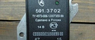
The following devices are found on machines:
- early model G12, producing current up to 20 A;
- G250, equipped with a built-in rectifier, develops power up to 350 W;
- improved 161 3771, equipped with an integrated voltage regulator;
- brushless products model G700A30.
All generator models are mounted on the crankcase of the power unit on the right side with a special bracket. The drive uses a belt stretched between pulleys. The lower support of the generator allows the unit to be moved a short distance, providing drive tension.
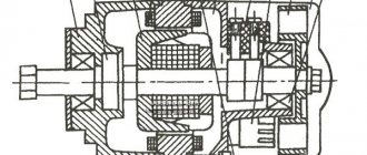
- Outer casing made of light alloy or steel (on early models). At the ends there are covers in which the rolling bearings are located. The back cover on a number of models is used to install the rectifier unit, brushes and voltage regulator.
- Inside the housing there is a package of steel sheets with a wound wire that forms a 3-phase winding. A device called a stator is used to generate current.
- Inside the stator, a rotor rotates on bearings, on which steel bushings and an excitation winding are placed. The wire leads are attached to the collector. On the outside of the stator there is a shaft with a recess for a key, which is used to mount the drive pulley. The part is secured with a nut. An impeller is installed in front of the pulley to supply cooling air inside the device.
- A spring-loaded brush assembly is used to supply excitation voltage.
- The rectifier bridge consists of 6 diodes.
About contactors
Thus, the use of conventional relays is out of the question for us; only specialized contactors are suitable.
For higher powers there is also an option with motorized drives, but this is expensive and redundant for typical home use. To make a mechanical interlock, you need to select contactors that can work in pairs. Typically, mutual interlocking is achieved by installing identical contactors next to each other and installing an additional option - a mechanical interlock. It is sold separately from contactors and costs pennies.
Mutual electrical interlocking is possible if the contactor has additional signal contacts that operate to open. Sometimes they are immediately built into the contactor, sometimes they can be purchased and installed as an option.
Leading contactor manufacturers have such equipment in their lines. So finding and buying a kit is not difficult. True, prices for branded contactors are an order of magnitude higher than ours/Chinese ones. Since the number of switching cycles is not expected to be large, the choice of Chinese contactors is quite justified. The only disadvantage is that the contactor coils hum quite loudly during operation.
More about the switching power. The contactor contacts must be able to handle the maximum amount of power you are allowed to draw in your home. For me it is 10 kW, so I chose contactors for a permissible current through one contact of approximately 50 amperes. It is worth noting that for some reason the switched power for a typical three-phase contactor is indicated in the passport as the total for all three phases, so you need to carefully look at what the permissible current is through exactly one contact.
About the control scheme
When I was creating an AVR, I had several special requirements for its operation:
- My electricity doesn’t go out that often, so I decided that I didn’t need the autostart of the generator, but I decided not to give up the automatic stop of the generator: when the network is restored, the generator itself goes quiet and it’s immediately clear that now everything is fine with the power supply, and gasoline is saved
- After starting the generator, you need to give it time to warm up and only after warming up give it a load. Those. I needed a timer to turn on the ATS after applying voltage from the generator
- After the network voltage was restored, repeated outages often occurred after a short period of time, so I needed a timer that would wait a while before switching from the generator to the network and would not immediately turn off the generator
- They say it is useful for the generator to run a little without load before turning it off. And for this I also needed a timer
Thus, the picture emerged that I needed a controller with several timers.
At that time, I was interested in coding on AVR, so I decided to make such a controller on Atmega 8a. It would be nice if the controller worked for a long time and reliably. Besides, I couldn’t think of anything else to make a complete galvanic isolation and equip the controller with a watchdog timer. Well, make the diagram and program as simple as possible. Since I was doing everything for myself, I decided to leave all the settings and calibrations in the code - the entire UI was reduced to one LED)
The main task of the controller is to monitor the voltage at the inputs and, if necessary, switch the inputs. In this case, input from the village network has priority.
It is worth noting here that the quality of the network is such that fluctuations from 150 V to 250 V are quite common. Therefore, the concept of good mains power is very vague. After some time, I solved this problem when I installed one powerful 11 kW thyristor voltage stabilizer for the whole house. But, it’s important, the stabilizer can only be installed before the AVR, and not after! It is strictly not recommended to turn on the stabilizer for the generator. There is a danger that under a certain combination of loads, especially any powerful pumps, the system of a generator and stabilizer will become unstable and enter into self-oscillations.
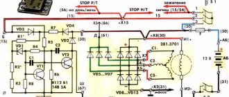
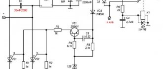
After some thought, I drew such a diagram in Eagle.
The circuit has two identical transformer power supplies; if there is voltage at any of the inputs, the circuit is provided with power. A voltage of 600V is possible between the inputs, so the insulation of the transformers must be good. Power is taken after the QF3 and QF4 packets, respectively.
Each source has a resistive voltage divider, protected from overvoltage by a zener diode - from it, the network voltage is measured using a microcontroller ADC using simple calculations.
To switch the contactor coils, a standard circuit from the datasheet is used to control semistores. 2 pieces ). Coils are an inductive load, so snubber circuits at the resistor and capacitor output are required.
I had a relay module with Ali that is used to stop the generator. In the diagram it is just a rectangle with three pins.
Among the features, the TL431 is also used as a reference voltage generator. Otherwise, everything is included as standard for Atmega 8. There are LEDs to indicate the presence of supply voltage at the inputs and one device status LED. The circuit is clocked using an external quartz at 16 MHz.
Eagle gave me this printed circuit board. No SMD, triacs and stabilizer with light radiators.
Two toroidal transformers are installed directly on the board. The board was made using the traditional amateur radio method using photoresist. After installation, I covered it with three layers of acrylic varnish. I hope the high voltage doesn't break through.
Purpose of the voltage regulator relay
Regardless of experience and driving style, the car owner cannot ensure the same engine speed at different times. That is, the crankshaft of the internal combustion engine, which transmits torque to the generator, rotates at different speeds. Accordingly, the generator produces different voltages, which is extremely dangerous for the battery and other consumers of the on-board network.
Therefore, replacing the alternator regulator relay should be done when the battery is undercharged or overcharged, the light is on, the headlights are flashing and other interruptions in the power supply to the on-board network.
Interconnection of car current sources
The vehicle contains at least two sources of electricity:
- battery - required at the moment of starting the internal combustion engine and the primary excitation of the generator winding; it does not create energy, but only consumes and accumulates at the time of recharging
- generator – powers the on-board network at any speed and recharges the battery only at high speeds
Rice. 2 In the car, the generator and battery are combined into a common network
Both of these sources must be connected to the on-board network for the correct operation of the engine and other electricity consumers. If the generator breaks down, the battery will last for a maximum of 2 hours, and without the battery, the engine driving the generator rotor will not start.
There are exceptions - for example, due to the residual magnetization of the excitation winding, the standard GAZ-21 generator starts on its own, subject to constant operation of the machine. You can start a car “from a pusher” if it has a DC generator installed; with an AC device, such a trick is impossible.
Rice. 3 Starting the internal combustion engine from the pusher
Voltage regulator tasks
From a school physics course, every car enthusiast should remember the principle of operation of a generator:
- when the frame and the surrounding magnetic field move mutually, an electromotive force arises in it
- The stators serve as the electromagnet of DC generators, the EMF, accordingly, arises in the armature, the current is removed from the collector rings
- In the alternating current generator, the armature is magnetized, electricity appears in the stator windings
Rice. 4 Operating principle of a car generator
In a simplified way, we can imagine that the magnitude of the voltage output from the generator is influenced by the value of the magnetic force and the speed of rotation of the field. The main problem of DC generators - burning and sticking of brushes when removing large currents from the armature - has been solved by switching to alternating current generators. The excitation current supplied to the rotor to excite magnetic induction is an order of magnitude lower, making it much easier to remove electricity from a stationary stator.
However, instead of terminals “–” and “+” constantly located in space, car manufacturers received a constant change in plus and minus. Recharging the battery with alternating current is not possible in principle, so it is first rectified with a diode bridge.
Rice. 5 Generator rectifier
From these nuances the tasks solved by the generator relay flow smoothly:
- adjusting the current in the excitation winding
- maintaining a range of 13.5 - 14.5 V in the on-board network and at the battery terminals
- cutting off the power to the excitation winding from the battery when the engine is turned off
Rice. 6 Purpose of the voltage regulator relay
Therefore, the voltage regulator is also called a charging relay, and the panel displays a warning light for the battery charging process. The design of alternating current generators includes a reverse current cut-off function by default.