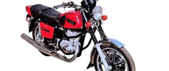
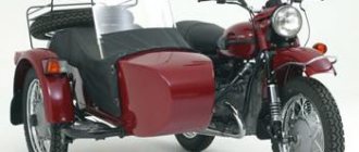
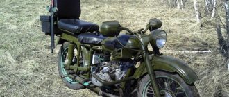
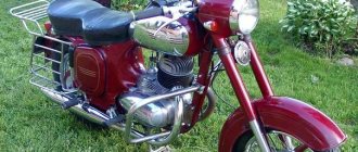
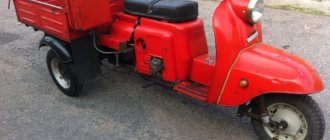
A classic motorcycle is a two- or three-wheeled vehicle (sidecar) with a mechanical engine, the distinctive features of which are gearless control of the front wheel, an upright position of the motorcyclist and the presence of footrests. A typical representative of this class is the Ural family of heavy motorcycles, mass production of which until recently was carried out at the Irbit Motorcycle Plant (Sverdlovsk region). Moreover, the motorcycle engine is a two-cylinder opposed power unit with a cylinder capacity of 650 to 750 cm3. The engines of the Ural motorcycle have great power, which allows you to confidently overcome the off-road conditions typical of the Russian outback. In addition, these power units are resistant to harsh climatic conditions - they start easily even in 30-degree frost. At one time, this made the Ural motorcycle, equipped with a sidecar, a worthy and relatively inexpensive alternative to a car, for example, in agriculture and/or when transporting small loads.
Currently, heavy Ural motorcycles with sidecars are popular mainly among collectors who are willing to pay decent money for them. For example, a Ural from the first years of production with a sidecar in the basic configuration costs about 12 thousand euros.
Ural M 72 technical specifications
Total information
Motorcycle type: with sidecar. Wheelbase, mm — 1430. Ground clearance, mm — 130. Track, mm — 1100
Dimensions, mm: — length — 2420; — width — 1650.
Height (by ignition key) - 1000
Motorcycle weight, kg: — dry — 335; - worker - 380.
Fuel consumption on the highway, l/100 km - 7. Fuel reserve on the highway, km - 310. Highest speed, km/h - 85.
Capacity (oil), l: - engine crankcase - 2.0; — gearbox housing — 0.8; — reverse gear housing — 0.150; — air purifier — 0.2.
Fuel tank capacity, l - 22.
Engine
Engine type: four-stroke two-cylinder. Brand - M-72M. Cylinder diameter, mm - 78. Piston stroke, mm - 78. Working volume, cm³ - 746. Compression ratio - 5.5 ± 0.2. Maximum power, l. With. — 22. Maximum torque, kg m — 4.0. The block head material is aluminum alloy. The head gasket is asbestos metal 0.6 mm. The piston material is aluminum alloy.
Valve distribution phases (according to the angle of rotation of the crank), degrees: - beginning of intake to c. m.t. - 76; - end of intake after n. m.t. - 92; - beginning of release BC m.t. - 116; - end of release after c. m.t. - 52.
Carburetor - Two K-37.
Power transmission M-72 M
The final drive ratio is 4.62. The clutch is a dry double-disc clutch in the engine flywheel.
Number of disks: — leading — 3; — slaves — 2.
Number of springs - 6.
Technical characteristics of the M-72 M gearbox
Type - four-stage two-way.
Gear ratios: — in first gear — 3.6; — in second gear — 2.286; — in third gear — 1.7; — in fourth gear — 1.3.
Total gear ratio: - in first gear - 16.65; — in second gear — 10.56; — in third gear — 7.85; — in fourth gear — 6.01.
M-72 M motorcycle tires and their characteristics
Size, in inches - 3.75-19.
Pressure, kg/cm²: — front wheel — 1.6; — rear wheel — 2.0; - stroller wheels - 1.8; — spare wheel — 2.0.
Ignition and Electrical Equipment M-72 M and their characteristics
Type - battery magneto. Ignition coil brand - B - 2B or B-11. The battery is 3MT-14. Generator - G - 11A. Relay regulator - PP-31. Signal - C - 23B. Headlight FG - 6.
Return to contents — ↑
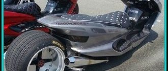
Stages of turning a Dnepr motorcycle into a custom one
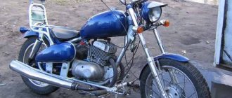
Perhaps this is said loudly about turning the Dnepr motorcycle into a custom one. Because more often such alterations fall under the definition of tuning. What is the difference between custom and tuning?
Tuning is the alteration of individual spare parts or components of a motorcycle. A custom motorcycle is a bike that has been completely modified to suit the owner's wishes. Moreover, it becomes unique and inimitable.
Stages of turning a Dnepr motorcycle into a custom one:
- engine replacement or upgrade
- front fork upgrade
- chassis modification
- exhaust replacement
- adding decorative elements
The engine is additionally cleaned and polished. This is done on purpose so that it does not differ from new parts. Various rings or a direct flow system are installed on the exhaust. You can also add a decorative nozzle.
Engine m 72
The engine of the Ural M 72 motorcycle is a two-cylinder, four-stroke engine; according to its design features, it can be classified as a forced road-type engine (despite the lower valve timing mechanism), since its compression ratio, speed and power are quite high. The engine on heavy motorcycles from the Irbit plant has an opposite arrangement of cylinders in a horizontal plane, which ensures good balancing of the inertial forces of the crank mechanism and reliable cooling. A gearbox is attached to the engine, connected via a clutch.
The cylinders are cast from alloyed or modified cast iron. The valve boxes are cast integrally with the lower cylinder support flanges. The left cylinder is moved slightly forward in relation to the right one. The cylinder heads are cast from aluminum alloy and have double ribbed bottoms for better cooling of the cylinders of the Ural M 72 motorcycle engine. An asbestos-metal gasket is installed between the head and the cylinder.
The pistons are cast from a special aluminum alloy, which contributes to their better cooling. Two compression rings are installed in the upper grooves of the pistons. In the lower groove there is an oil collection ring. The lower groove has through cutouts designed to reduce heat transfer from the head to the piston skirt and to remove oil removed by the oil collection ring from the cylinder walls. The piston rings are made of special cast iron. All rings have straight locks, the gap in which in the working position is 0.25-0.45 mm.
The connecting rods have one-piece heads. Bronze bushings are pressed into the small heads, and single-row roller bearings with cages are inserted into the large ones. The small head is connected to the piston using a floating piston pin. The rollers of the large head roll along the surface of the crankshaft journal, which has two elbows with crank radii of 39 mm. The crankshaft assembly with connecting rods is an integral unit, since its disassembly and reassembly is impossible without special tools.
The durability of this unit is guaranteed by the factory within 15,000 km. When assembled, the shaft is installed in a one-piece crankcase on two ball bearings. To mount the engine to the motorcycle frame, there are special bosses with holes for through bolts in the lower part of the crankcase.
Motorcycle engine M 72 (disassembled). 1 — front crankcase cover; 2 — breather tube; 3 - lock nut; 4 — camshaft oil seal; 5 — oil seal body; 6 — distribution head cover; 7 — breather; 8 — camshaft gear; P - camshaft; 10 — camshaft flange; 11 — camshaft bearing; 12 - sealing gasket; 13 — camshaft bushing; 14 - crankcase; 15 — generator gasket; 16 — generator gear; 17 — connecting rod; 18 — oil pump drive gear bushing; 19 — gear; 20 — gear plug; 21 — generator stop; 22 — valve box cover and gasket; 23 — cover screw; 24 - flywheel; 25 — flywheel pin; 26 — lock washer and flywheel mounting bolt; 27 — bolt and lock washer of the crankshaft gear; 28 — crankshaft gear; 29 — bearing housing cover; 30 - bearing; 31 — bearing housing; 32 - crankshaft; 33 - oil catcher; 34 - sealing gasket; 35 — rear crankshaft bearing housing; 36 — oil seal; 37 — roller bearing separator of the large connecting rod head; 38 — roller; 39 — connecting rod; 40 — connecting rod small head bushing; 41 — piston pin; 42 - piston; 43 — oil scraper ring; 44 - compression ring; 45 — oil line pipe; 46 - defoamers; 47 — crankcase spacer; 48 - sealing ring; 49 - plug; 50 - coupling; 51 — oil pump housing gasket; 52 — oil pump housing; 53 — oil pump gears; 54 — oil pump housing cover; 55 — oil pump filter; 56 - pallet; 57 — pan sealing gasket; 58 — drain plug and sealing washer; 59 — cylinder gasket; 60 — left cylinder; 61 — carburetor gasket; 62 — cylinder head gasket; 63 — cylinder head; 64 — cylinder head mounting bolt; 65 — upper valve spring plate; 66 — valve spring sealing gasket; 67 - valve; 68 — valve spring; 69 — lower valve plate; 70 - cracker; 71 — bolt and locknut of the pusher; 72 — pusher guide; 73 — pusher; 74 — pusher guide bar; 75 — strip pin.
Return to contents — ↑
Motorcycle engine lubrication system Ural M 72
Motorcycle engine lubrication Ural M 72 has a combined lubrication system. The engine is powered by two caburators. The bearings of the large connecting rod heads, the left cylinder and the timing gear are lubricated under pressure. The remaining parts are lubricated by spraying oil with oil mist. The lower part of the engine crankcase is covered with a stamped steel pan, which is a reservoir 19 for oil, the capacity of which is 2 liters.
The Ural M 72 motorcycle engine is lubricated under pressure using a single-stage gear pump 1, driven from the engine camshaft. When the engine is running, gears 2 and 3 drive oil into the main oil line, and from there to two oil catchers 12, to the upper wall of the left cylinder and to the crankshaft drive gear. After this, the oil is sprayed onto the rubbing surfaces of the parts of the crank mechanism and the gas distribution mechanism. A spool breather is mounted in the distribution box housing, rotating together with the camshaft gear and designed to reduce oil pressure in the motorcycle engine crankcase.
Return to contents — ↑
Motorcycle engine power supply Ural M 72
The engine power system of the Ural M 72 motorcycle includes a fuel tank with a capacity of 22 liters, a three-way valve KR-16 and two carburetors K-37 A, which have one common air cleaner, suction and exhaust pipes. Carburetors have the same design, but are not interchangeable (left and right).
The K-37 A carburetor consists of a body, with which the float chamber is cast in one piece. The latter is closed by a lid 3, in which there is a drowner 5. When you press the drowner, the float lowers, the fuel level in the chamber rises, and the mixture entering the engine cylinders is enriched. The power system prepared the motorcycle engine for starting.
To automatically regulate the fuel level in the float chamber, there is a shut-off needle 4, controlled by a hollow float 6. Fuel enters the float chamber until the float floats up together with the shut-off needle, and the latter, with its upper conical end, closes the fitting hole in the float chamber cover . The fitting has a mesh filter 8, designed to filter fuel.
There are two holes at the bottom of the case. The nozzle 10 is screwed into the upper hole, into which, in turn, the main jet 9 is screwed. The fitting 7 with filter 8 is screwed into the lower hole. The nozzle communicates with the mixing chamber through an air channel.
Low speed (idle) jet 13 is screwed into the lower part of the carburetor body. The nozzle is closed from below with a locking screw 21, which is intended for purging the nozzle. Fuel is supplied to the low-speed jet from the float chamber through channel 14, and air is supplied from the air pipe through air channel 16 and an additional channel connected to air filter 17. Air channel 16 is closed by adjusting screw 18 with a lock nut.
Above the sprayer there is a throttle valve 2 with a needle 12 and a spring 23. The valve has a bevel on the side of the air entering the pipe, and on the side surface there are two longitudinal grooves.
The throttle needle enters the internal channel of the main jet nozzle, due to which fuel flows to the nozzle through the annular gap between the wall of the nozzle channel and the needle. There are four holes at the top of the needle. If you combine these holes alternately with two holes in the spool housing, you can get eight different height positions of the needle.
The lower the needle is, the poorer the mixture, and vice versa.
The throttle spool moves along a guide, which is closed on top by a cover 24 and secured with a union nut 25. Spring 23 presses the spool down, and the upward movement of the spool is limited by stop 20. This stop (limiter) during the break-in period does not allow the engine to be given high speeds and overloaded.
Throttle spools are raised or lowered by rotating the throttle knob, which is connected to the spools using cables, in the appropriate direction. Both spools must be actuated and work synchronously, which is achieved by a certain installation of the stops of the cable sheaths 26, followed by tightening the locknuts 27.
Return to contents — ↑
The gas distribution mechanism of the Ural M 72 motorcycle engine
The gas distribution mechanism of the Ural M72 motorcycle engine has a lower (side) valve arrangement.
The camshaft is mounted in the upper part of the crankcase on two bronze bearings (manufactured before 1955). On later motorcycles, the front bronze bearing was replaced by a ball bearing.
The camshaft receives drive from the engine crankshaft through a pair of helical gears.
Five cams are integral with the shaft: two suction, two exhaust and one ignition cam.
The latter serves to open the breaker contacts.
The lifting of the valves during operation of the gas distribution mechanism of the Ural M 72 motorcycle engine is carried out through rectangular flat pushers made of cast iron with bleached working surfaces.
The pushers move in aluminum guide bushings.
Reliable engine operation is guaranteed if there is a thermal gap between the pushrod bolts and the valve stems. This gap for a cold engine should be 0.1 mm.
Return to contents — ↑
Soviet motorcycle Dnepr and fuel system
Many of those who have already owned a Dnepr motorcycle know that it has problems with the fuel system. It is for this reason that some people replace the engine during tuning. In my opinion, this is a controversial idea.
It is better to purchase an enlarged pan with a filter and install it on a standard engine. Our model allows you to screw in a magnet and thereby add magnetic separation. There is also a small modification inside in the form of an oil bath. You can find out more in the previous article: Enlarged pallet for the Dnepr motorcycle.
Controlling a motorcycle Ural M 72
The Ural M 72 motorcycle is controlled by mechanisms located on the steering wheel and having a manual drive.
In addition, there are a pair of brake pedals and a gear shift lever.
Manual control mechanisms include: throttle handle, front brake lever, clutch lever, combination shifter.
The gas handle, located on the right half of the steering wheel, is connected to the carburetors using flexible cables. To increase the engine speed, you need to turn the throttle towards yourself, and to decrease it away from you.
The front brake lever is hinged on a bracket on the right side of the steering wheel and connected to lever 24 by a flexible cable. To brake the front wheel, the front brake lever must be pressed against the steering wheel handle.
The clutch lever is located on the left handlebar and is connected to the clutch lever 19 using a flexible cable. To disengage the clutch, the clutch lever should be pressed against the steering wheel handle.
The combined shifter is designed to force the ignition advance, switch the headlight light and turn on the electric signal.
Return to contents — ↑
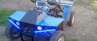
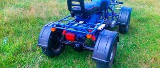
Tuning the Dnepr motorcycle for the people
It is not uncommon for people to begin to invent and improve this motorcycle themselves, using all their technical knowledge and imagination.
And the reason for this was the availability of parts from which something new can be made or added to those already installed. High wear resistance and long service life only encourage many to tune the Dnepr motorcycle. This is precisely one of the main reasons to choose the Dnepr over any other motorcycle.
The Soviet Dnepr motorcycle is a classic example of the old-fashioned Soviet school of rough design. Therefore, many people prefer to customize its appearance and some structural components.
Moreover, remaking it is not a difficult task, compared to a foreign car. If you follow all the recommendations, you can transform this motorcycle very coolly. That is why workshops have appeared all over Russia that do tuning of the Dnepr motorcycle. And some even turn it into a real custom for the people.
Electrical equipment of the motorcycle Ural M 72
The electrical equipment of the Ural M 72 motorcycle consists of the following devices and units: a G-11A generator; battery Z-MT-7 or Z-MT-14; relay-regulator RR-31; ignition coils IG-4085-B; breaker-distributor PM-05; spark plugs NA11/11AU; FG-6 headlights, lighting lamps, signal, switches and warning lamp.
The spark plug NA11/11AU is a collapsible type, consisting of: uralite insulator 1; central electrode 4; steel body 2; side electrode 5; insulator nuts 3; two copper gaskets 6; one copper-asbestos gasket 7. The central electrode is covered on top with a carbolite tip 5. The spark gap between the central and side electrodes should be 0.7 mm.
The FG-6 headlight consists of a housing 1, a rim 2 with a lens, a reflector 3 with a double-filament lamp 4 and a parking light lamp 5. The headlight housing contains a central switch 6, a high and low beam switch 7, a speedometer 8, a warning lamp 9 and a fuse 10 The various positions of the central switch are switched on using key 11. There are wire holders on the sides of the headlight housing.
Electrical diagram of the M 72 motorcycle.
1 – double-filament lamp; 2 – ignition key; 3 – fuse; 4 – headlight; 5 – central switch; 6 – reflector wire to ground; 7 – high voltage wire; 8 – candle; 9 – high voltage wire; 10 – ignition coil; 11 – side lamp; 12 – signal; 13 – wire for the rear light of the stroller; 14 – lamps for the rear light of the stroller; 15 – motorcycle taillight lamps; 16 – brake light sensor; 17 – relay regulator; 18 – generator; 19 – battery; 20 – low voltage wires; 21 – battery ground wire; 22 – breaker; 23 – distributor; 24 – high voltage wire; 25 – connecting wires of the breaker with the ignition coil; 26 – signal button; 27 – signal wire; 28 – ignition timing lever; 29 – light switch cable; 30 – light switch; 31 – control lamp; 32 – parking light lamp; 33 – speedometer lighting lamp; 34 – motorcycle-sidecar wire connector; 35 – wire for the rear light of the stroller; 36 – wire for the rear light of the stroller; 37 – Sh, Z and B – relay-regulator terminals.
The design of the remaining electrical devices and units of the Ural M 72 motorcycle is given in the description of the electrical equipment of the K 750 motorcycle.
The required driving tool is shown below.
Return to contents — ↑
How to select timing gears depending on the crankcase group
The selection of an internal combustion engine seal kit is selected according to the table below, where an index is indicated under the crankcase group.
| Crankcase group | 0 | 1 | 2 | 3 | 4 | 5 | 5,5 |
| Suitable indexes for gear sets after 1991 | 0 | 1 | 2 | 3 | 4 | 5 | 5,5 |
| According to labeling before 1991 | 13-18 | 12-17 | 11-18 | 10-15 | 9-14 | 8-12 | 6-10 |
| Correspondence of the indices of the timing gears “HERZOG” of the new Ural 750cc engines. | 0 | 1 | 1 or 2 | 2 | 2 or 3 | 3 | — |
If you do not find a set of timing gears with the required indices, you will have to make a test shaft from an old CV with a mounted bearing for installation in the seats without interference. To do this, you need to grind the outer race of the bearing and the seats for the gear and bushing. Try to maintain minimal clearances so that the shaft with the bearing and the gear do not dangle in the fit. In this way, you can use the selection method to select the gear with the smallest lateral clearance when mating with the KV gear, but in this case you need to take the crankcase and the test shaft with you to the store.
