How to change bearings in the steering column
The steering column is one of the most important and most loaded components in the chassis of a motorcycle. The condition of the steering bearings directly affects the handling and safety of riding a bike. Old, worn-out bearings can lead to play in the entire front suspension, which will affect the quality of its operation and, accordingly, the grip of the wheel on the road. The motorcycle may even stop going straight. In the worst case scenario, the old bearings will simply seize.
To understand whether it’s time to change the bearings in the steering column, you need to hang the front wheel completely (rolling it under the yoke will not work). Then, with both hands, grab the fork from below and move it along the axis of the motorcycle. The play will manifest itself as a tapping sound in the area of the steering column. To eliminate play, sometimes it is enough to tighten the adjusting nut. If the adjustment did not help or you do not know when and how the steering bearings were changed on your motorcycle, replacing them would be a good solution. This is a relatively simple task, although it requires a little skill. Everything can be done in any garage with improvised tools.
Most motorcycles use inexpensive ball bearings. They wear out faster and withstand less load than tapered roller ones. In addition to the bearings themselves, we will need a new boot for the lower bearing.
Dismantling
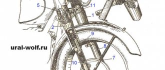
So, to get started, you need to remove everything unnecessary from the motorcycle: the front wheel, fender, damper, head fairing, fork and clip-ons (or handlebars, if you have the wrong motorcycle). Unscrew the axle nut securing the upper crossmember. We remove the traverse. You may have to tap it from below. Now we need a key for the round spline nuts. For example, a key for adjusting the shock absorber spring preload. A bicycle “family bike” is also suitable. A makeshift extension cord wouldn't hurt either.
In front of us are two spline nuts. Carefully bend the upper petals of the locking ring and unscrew the fixing nut, remove the ring and unscrew the adjusting (lower) nut.
Holding the lower yoke with your hands, remove the upper boot and bearing. Now we take out the traverse with the steering axle and the bearing on it. As you can see in the photo, during a previous bearing replacement, an old damaged boot was left on the motorcycle, which allowed dirt and moisture to get inside.
Lower bearing
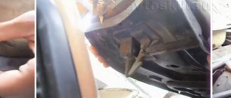
Now comes the hard part. The inner ring of the lower bearing and the old boot remained on the axle. It's not that easy to remove. On the Internet, it is generally recommended to cut the ring with a grinder (more precisely, with an angle grinder). The Honda manual insists on using a chisel or a small chisel and hammer. We remove it using the official method.
Before starting to work with a chisel, you need to screw the nut securing the upper cross-arm onto the axle. This will protect the threads from damage. After half an hour of dancing with a hammer and chisel, the axle is finally free. Minor damage is inevitable, no big deal. Now you can install the new bearing.
We put the boot on the axle, then the new bearing and put the inner ring of the old bearing on top with the opposite side. Now, using moderate blows of a hammer through an extension (or a pipe of a suitable diameter) and the old ring, we push the new bearing onto the seat. We knock until the boot stops hanging around. To facilitate the process of seating a new bearing, we will use knowledge about the thermal expansion of materials. Let's put the axle in the freezer for a couple of hours, and heat the new bearing. The process will be easier. The main thing is to do everything quickly, until the temperature of the parts is equalized. And don't forget about the duster!
Bearing races in the frame
Let's put the traverse aside and move it to the frame. There are cages left in it from old bearings that need to be replaced with new ones. We'll use a socket extension and a hammer. The extension cord is placed in special grooves inside the frame and rests against the edge of the holder. The clip is knocked out with light and uniform blows around the entire perimeter.
Now you can lubricate the seats and install new clips. Their old brothers will help us with this. We place the new clip in its seat, put the corresponding old clip on top with the reverse side, and hit it evenly with a hammer. We hammer in the rings until they stop. Now the bearings need to be lubricated. A grease containing molybdenum disulfide can be used. It is important to lubricate both bearings and their races well. You should literally rub the grease into the bearing. The adjusting nut covering the steering column must be lubricated with engine oil. This is necessary for the next step.
Assembly and adjustment
We assemble the entire structure. We place the lower yoke and the axle with the bearing installed on it in the steering column. We put a bearing and boot on top of the axle. Tighten the adjusting nut with an initial torque of about 30 Nm
Repair of the wheel hub of a URAL motorcycle
How I disassembled and reassembled the hubs. Attention! Below is described what I did, consistent with what I had read earlier and what I had learned in the process. I don’t know how correct it really is.
A little bit about the prerequisites. When driving, regardless of speed, the front suspension began to shake randomly (as if the wheel was oval). Even if you stood up and pumped the shock absorbers while simultaneously changing the speed mode, the vibrations were eliminated only when the speed was significantly reduced. EMNIP, at speeds above 80 km/h there was never any shaking. Well, accordingly, suspicion of a malfunction fell on the entire front part. I’ll start with Tutov from the bottom - from the wheel hub.
I did not take measurements on a hanging fork. I removed both wheels at once (I’m just going through everything at the same time). The left spacers of both wheels showed good play. The right front hub bearing also showed slight play when rocking with fingers. The wheel, put on an axle secured accordingly, did not cause any major complaints, but did not show any “iron” fastening either. Nearby there were two manuals (both made in the hub plan), a CV joint bank, 4 7204 bearings (KRAFT, I don’t remember about the letter A in the index), and two sets of bushings with “nut assemblies”.
The hub consists of (from left to right as the motorcycle moves): a special nut (a big fool with 4 eyes for a radius wrench) a nut assembly (also a fool, with 4 holes at the end of the wrench, with a gasket and a washer cored at the back. The left spacer is included in the package ) bearing intermediate sleeve with washer (in the middle of the sleeve there is a square plate with corners rounded to fit the radius of the hub. Moves freely) bearing right spacer sleeve thrust washer garage space.
Please note that the bearings are located with their wide parts inward . In other words, the bearing housings are located outside.
What to do, how to take it apart. Remove both nuts (which are healthy fools). Next, if you only need to change the lubricant, then knock out the filling on the right bushing (the right bearing housing remains in place). The bearing will not be damaged, because its inner wall rests against the intermediate sleeve, and the right bearing doesn’t give a fuck, because... he has no choice. If you need to replace everything, then use a 30mm head to knock out everything else (I knocked everything out at once) through a thrust washer (the washer has a convexity in the middle, which can be damaged by a smaller diameter of the head (punch).
How to assemble it. I lubricated everything with CV joints without skimping. After cleaning and lubricating the walls. First comes the thrust washer with its bulge forward (that is, to the right). Then comes the right bearing housing (which side, see above). I worked through head 32, but it didn’t quite reach the end (it hit the inner wall of the case), but experimenting with a vice, a sledgehammer and the old case gave the go-ahead. But it’s better to find something a little wider in diameter, because... due to the “floating” contact between the head 32 and the body, the impact load was “curved” and distortions occurred. The idea of putting an old thrust washer under the head came to my mind already on the way home. Attention! The housings of both bearings settle easily, but when misaligned they stand up tightly. It is useless to hit the “under-planted” part; you have to knock it out and start again. The hub walls between the bearing seats have a slightly larger diameter. If the body doesn't work, you need to knock it out and start again. According to observations, if the body is 3/4 in the seat, it will no longer warp. I controlled the degree of shrinkage of the right bearing housing with my finger - the gap between the thrust washer and the bearing housing. It shouldn't exist. Next, I lubricated the bushing, inserted it, then lubricated the bearing, inserted it, then lubricated the intermediate bushing along the entire volume between it and the hub body, and inserted it. Then I installed the left bearing and pressed the housing. The shrinkage of the left housing was controlled by the radial movement of the left bearing. Tighten the nuts as written below. Then I coated the right outer part between the hub body and the spacer sleeve with lubricant, stuck on a protective cap and placed it against the wall. That's where I'm done for now. The question remains: did I go too far with the lubricant?
The theoretical part, which I will practice later. The manual instructs to tighten the nut assembly (with the spacer sleeve) until it stops by hand, then unscrew it 1/5-1/6 turn and lock it with a special nut. Then drive 6 km without stopping or braking, touch the hub body. If it is hot, then loosen the nut a little more. Check. If everything is in order, then further monitoring and adjustment of the gap should be carried out 500, 1000 and 2500 km after working with the hub.
High-quality Korean wheel bearings for Ural Dnepr. Replacement and adjustment of wheel bearings.
High-quality spare parts for Soviet boxer cars are a real headache for every owner in modern realities. My solution is to use suitable parts from modern cars as much as possible. They are often cheaper than their motorcycle counterparts due to mass production and are of better quality if you choose the right manufacturer. Everything is on video, and if anyone forgot how to assemble and adjust the wheels, I also filmed that.
Regarding the manufacturer - I used Parts-mall PSC-009 bearings and as the owner of a Korean car, I assure you that these are excellent analogues, which are the supplier of the Daewoo-GM conveyor. The same cannot be said about “Korean-type” AMD bearings, which they can offer you as an analogue. they are two or three times cheaper when purchased, and this is weak Chinese, be careful!
Attached videos:
- I like I like 2
Other entries in this logbook
How to install an oil pressure indicator on a Dnepr motorcycle.
A detailed description of such a simple but very important modification to my Dnepr motorcycle, installation of a mechanical pressure gauge. Usually everything is on the Internet. Read more
Blog named after DobryiD_Sw → A trip to the Black Knives bike festival in the ancient Urals with a stroller.
We have been coming here for a long time, the first time we were in Aramil at the second Rally as schoolchildren, at Izhaki, without a license, and today the fifteenth is already taking place (. Read more
How to check the boxer crankshaft without disassembling the engine.
You've probably already started to worry why there are no new videos. The bottom line is that the more work I do on the motorcycle, the less output I have. Read more
Comments
Only authorized users can leave comments
Rear axle of a Ural motorcycle. We change the main pair.
Riding with an 8-wheel drive in the rear axle of a motorcycle did not bring satisfaction, especially since the rear wheel had a 16” rim. The engine roars at maximum speed, and the speed barely reaches 90 km/h. It was decided to change the main pair in the rear axle of my Dnepr motorcycle.
I had a stroller pair (8/37 with a ratio of 4.63), and at the market I bought an accelerated pair (10/35 with a ratio of 3.5). I expected the speed increase to be about 32%.
I started by draining the oil from the bridge by unscrewing the bottom plug. I took off the rear wheel, disconnected the brake rod, unscrewed the four nuts securing the bridge to the pendulum, pulled it slightly towards myself, and now I have the bridge in my hands. The brake pads were removed and put aside.
I unscrewed the protective cover (cap) of the hinge; note that it has a left-hand thread. Next, I unscrewed the nut and carefully, so as not to spoil the thread, knocked out the wedge bolt securing the hinge. Lightly tapping the body of the hinge mechanism with a hammer, he removed it from the drive gear shaft.
Unscrewed the six nuts securing the crankcase cover. Some nuts came off along with the studs. By quietly tapping the crankcase cover with a hammer, he disconnected the cover and the crankcase. When I pulled out the cover, needles from the needle bearing fell into the crankcase. I carefully counted them all (45 pieces) and collected them in one place.
To remove the large gear from the crankcase cover, I had to screw in two long bolts in place of the studs securing the crankcase to the pendulum and slowly use them to squeeze out the hub with the driven gear.
I immediately cleaned the threads in the crankcase cover with a sword. Removed the thrust bushing from the driven gear hub.
Next, I unscrewed the aluminum shank nut. It also turned out to have a left-hand thread.
Pulling the shaft, shaking it a little from side to side, he pulled it out of the crankcase. The needle bearing remains in the housing. I removed all the needles from the bearing cage, there were 28 of them.
Removed the collar seal from the crankcase cover.
I knocked out the support bearing (207) through the holes in the hub and loosened the 8 bolts securing the driven gear to the hub. The bolts were loosened and unscrewed almost by hand. Removed the driven gear.
I washed the crankcase body and cover in gasoline.
I started installing the new driven gear on the hub. It turned out that the old mounting bolts did not fit on the new gear. Different thread pitch. I had to look for eight suitable bolts.
To properly tighten the bolts securing the driven gear to the hub, I had to use a motorcycle wheel. By inserting the hub into the grooves, you can easily tighten the bolts to the desired torque.
Next, I locked the bolts and installed the support bearing in the hub.
The drive gear did not fit into the crankcase housing. The inner flange against which the double-row bearing rested was in the way. I ground off the excess metal so that there was a stop for the bearing, but nothing prevented the drive gear from rotating in the crankcase. The crankcase was washed again with gasoline and blown dry with compressed air to remove sawdust.
Having compared the thickness of the old and new drive gears along the shaft axis, I saw that the new one (10) turned out to be “fuller” than the old one (8) by 1.3 mm. I had to take it to a turner and cut off the excess metal from the side of the double-row bearing so that the bearing could fit closer to the teeth.
After grooving, I installed the inner race of the needle bearing on the drive shaft. Using a spark plug wrench, I installed the double row bearing in place.
I removed two old oil seals from the aluminum nut and installed new ones in their place, having first slightly lubricated the side surfaces with engine oil. The seals didn't want to come into place completely, so I had to carefully put them in place through a wooden spacer.
Having thickly smeared the outer race of the needle bearing in the crankcase with lithol, inserted all the needles there and aligned them with a finger in a circle.
Installed the drive shaft into the crankcase and tightened the aluminum nut. The shaft rotated easily on bearings. The gear teeth did not touch the housing. Using a gas wrench, I finally tightened the aluminum nut.
The cardan joint was installed as follows. First, I inserted the hinge onto the shaft and looked into the hole in the wedge bolt. The holes in the joint and on the shaft matched, and this was incorrect. When installed, the wedge bolt would fall completely into the hole.
Using adjusting washers, I ensured that the holes did not coincide, and the hole in the hinge body was slightly ahead of the hole on the shaft.
Next, I inserted a wedge bolt into the hole with the ground edge forward, towards the crosspiece, and hammered it there with a hammer so that the wedge would pull the hinge onto the shaft and the hinge would rest against the adjusting washers. A small part of the wedge remained sticking out outside; he could not go any further. If the wedge goes inside the hinge body, then you need to add shims. I managed to install as many as five washers. After that I tightened the wedge bolt nut. The drive gear was finished.
After that I took up the driven gear. Placed the hub with the driven gear on the crankcase cover housing.
I applied lithol to the groove of the needle bearing on the hub and “glued” all 45 needles to the hub.
I put a new gasket on the crankcase and carefully inserted the cover with the driven gear into the crankcase. I tightened all the bolts and checked the rotation of the shaft. Everything spun without jamming. There was barely noticeable play when the drive shaft rotated left and right. That's how it should be. If, when installing the cover in place, the drive shaft rotates with jamming, then it is necessary to increase the thickness of the gasket or add a second gasket. If the play when rotating left and right is quite noticeable, then the gasket should be removed, replacing it with a thin layer of sealant.
I installed the axle on the motorcycle, filled in 125 grams of transmission oil and went to get new riding sensations!
Gilazov Vyacheslav.
The editors of the magazine thank Vyacheslav Gilazov for the kindly provided information and photographic material.
If you have something to share with readers and would like to publish your story or photo report about your travels on our website, please send the materials to:
This might be interesting
- Tuning the Izh motorcycle. BSZ on Izh Jupiter The main “soreness” of the Izh Jupiter motorcycle engine is the standard contact ignition system. Any owner of Jupiter...
- Contactless ignition system for a Ural, Dnepr motorcycle While solving the problem of the reliability of the ignition system on my Ural motorcycle, I came to the conclusion that it was necessary...
- On bicycles through the mountains This is a report on a journey by bicycles through the Caucasus Mountains of completely unprepared people. Read this article and you...
How to change bearings on a Ural motorcycle
REMOVAL AND INSTALLATION OF MOTORCYCLE WHEELS “DNEPR” AND “URAL”
Wheels are replaced or repaired if there are cracks in the rim, its ellipticity is more than 5 mm, if the brake drum diameter is worn more than 204.5 mm, and for the Ural M-62 motorcycle - more than 202.5 mm, if the bearing holes are worn - more
To remove the front wheel, place the motorcycle on a stand and hang it by placing a lining under the front part of the frame. Unscrew the coupling bolt nut of the left fork leg tip by several threads and turn out the front wheel axle, which has a left-hand thread; remove the front axle, while supporting the wheel, then remove the protective cap from the wheel, remove the wheel along with the brake cover and free it from the brake cover.
When removing the rear wheel, remove the cotter pin from the axle nut, unscrew the nut, then loosen the nut of the pinch bolt of the left tip of the pendulum fork, remove the axle
and remove the protective cap. Shift the wheel from the brake pads to the left and remove it from the frame. To remove the wheel of the side stroller, remove the cotter pin and unscrew the nut
and remove the protective cap. Place a stand under the frame of the stroller to hang the wheel, and remove it, and then the protective shield. Before installing the wheels in place, their axles are lubricated with engine oil.
The wheels require repair operations to install new spokes, eliminate axial (figure eight) and radial runout; replacement of bearings and hub seals, as well as replacement of friction linings of brake pads.
When installing one or more spokes to replace broken ones, new spokes are placed only in the corresponding pairs of holes in the rim and hub. When many spokes are broken, the appropriate holes for installing a new spoke should be determined by analogy with the location of the spokes on a good wheel.
Screw the nipples onto the installed spokes by hand or with a screwdriver until halfway through the threads, and then tighten them with a wrench.
Motorcycle Ural. #8. Replacing the main bearings and installing the crankshaft into the crankcase.
Published May 24, 2018
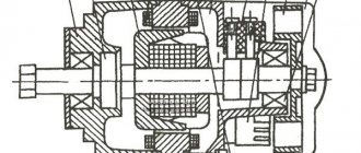
Gradual assembly of the engine began. The crankshaft is in its place and will now rotate on new Japanese Koyo bearings. I hope they don’t fail, but just in case I won’t throw away the old bearings. All critical fasteners are mounted on a removable threaded fastener. One that will not allow the screws to unscrew on their own, but if necessary, it is still possible to tighten them.
Before installing the crankshaft, the front bearing should have been heated and covered with a stamped cap - this would have simplified the installation. A very important thing was missed: if the rear cover does not have tension in the crankcase, then it is not recommended to install it. Because there won't be enough oil pressure to the rear support. The flywheel should have been ground to the crankshaft cone with valve lapping paste - this gives an almost 100% guarantee that it will not fall off. Before installing the rear crankshaft support housing, it was necessary to heat the crankcase and the inner bearing race in that place. And on such crankshafts you should never knock on the axle in the axial direction to seat another axle into the bearing - you must pull from the arc side. To do this, you could take a plate 4-6 mm thick, make 3 holes, the outer 2 of which are threaded. Take 2 small plates to support the bolts of the outer holes on them (so as not to damage the crankcase) and insert the crankshaft gear fastening bolt into the central hole and tighten it. Look like that's it. Good luck in the future!