- via door or motion sensor
- humidity sensor
- directly from a light bulb or lamp in the bathroom
But the most correct way to do this would be through a light switch installed on the bathroom lighting, or through a separate two-key switch.
How not to connect and why
The first options have a lot of inconveniences, which are not entirely noticeable at first.
For example, let’s say you set up the hood to turn on using a door opening sensor. At the same time, it turns off according to a timer after 5 minutes. It would seem very convenient.
However, it is quite problematic to install such a sensor on an interior door. Not to mention other aspects of operation. For example, what to do if you stay in the toilet longer than the set time.
Open and close the door again? What if there are guests in the kitchen?
In addition, the cables will have to be routed under the tiles, several extra holes will have to be drilled, etc. Simple motion sensors are sensitive to humidity and fail very quickly.
You will have to select expensive models with appropriate IP humidity protection, depending on the zones in the bathroom.
Some people consider the most convenient option to be installing a switch on the hood directly inside the bathroom. However, the PUE prohibits this.
Why this is so, the relevant links and explanations from Rostechnadzor specialists will be given at the end of the article.
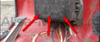
Alfa 110 moped wiring diagram
This abbreviation stands for Capacitor Discharge Ignition - ignition from a capacitor discharge. Sprinkle talcum powder on the inside of the tire. Electrical diagram of Delta 50 mopeds without a tachometer The photo below shows a schematic electrical diagram of the Alfa, Delta moped and other mopeds that do not have a tachometer.
Change the oil in the gearbox with a warm engine after the first km, and then regularly after km in the following order: remove the filler and drain plugs; drain the used oil; Screw in the drain plug and fill in approximately cm3 of oil; screw in the filler plug; let the engine run for 3-5 minutes, shift gears alternately.
When starting a cold engine, press the float stop 22 fig. Problem identification is done using a multimeter.
Place part of one bead of the tire in the recess of the rim, use a spudger and a wrench to push the entire bead of the tire onto the rim and slide it towards the rim flange.
Brakes To adjust the front brake, a stop is installed on the brake pad disc. Check the operation of the gear shift mechanisms, clutch, and brakes.
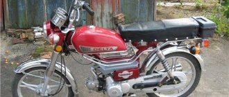
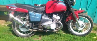
Protect the paper element from contact with oil and gasoline. Obe3obPasha Leave a comment Over the past few decades, the domestic moped manufacturer has completely left our market, and Chinese analogues and new models have taken its place. Electrical wiring for the 157QMJ engine (Simplified) or how to start the engine without a moped
Connecting a bathroom fan via a switch
Therefore, let's consider the most correct and reliable method - connecting from a lighting switch located on the outside of the bathroom.
For installation you will need very few materials:
- cable VVGnG-Ls 3*1.5mm2 or NYM 3*1.5mm2
Which one is better to choose, read the article “The best cable for wiring NYM or VVGnG-Ls”.
The body of most hoods is plastic, so these models do not need to be grounded. If you have ventilation with metal elements, then you will need a 4-core cable 4 * 1.5 mm2
- Vago terminal blocks
The loads here are small, so these terminals, controversial for many, would be quite appropriate here. There is no need for any twisting followed by welding, soldering or crimping.
- the exhaust fan itself with a timer
Varieties and characteristics
The ERA model is the most popular in our market. Let's look at it in more detail.
Other mechanisms and models with a timer from Vents, Ballu, Electrolux are connected in a similar way.
Here are the technical specifications and detailed data for all popular models:
Electrolux EAFM-100THERA SB D100 OptimaVents 100 KDomovent 100 CERA D 100 E 100SCBallu Green EnergyERA D 100 4C ETVents 100 Quiet
Operating modes of the hood in the bathroom
These fans with a timer have two operating modes:
- toilet - upper position of a special jumper
- bathroom - lower position of the jumper
Switching modes is done on the control board in the upper right corner.
Others have similar jumpers class=”aligncenter” width=”720″ height=”420″[/img]
When working in the “toilet” mode, after turning on the light and supplying power to the board, the ventilation immediately starts working. As soon as the light is turned off, the fan does not stop, but will continue to spin for a certain time.
You set this time yourself by unscrewing the adjusting screw with a screwdriver.
In the “bathroom” mode, the operation is somewhat different. This mode is suitable specifically for showers and bathrooms, without a toilet.
For example, if you are taking a shower or bath, the noise of the blades and drafts will only disturb you. Therefore, when the lights in the room are turned on, the fan does not work.
If the light was on for more than 90 seconds, then only after it is turned off will the hood operate and start. Its further operation will again last as long as you unscrewed the timer adjustment screw.
The whole thing is controlled from the light switch located in the corridor.
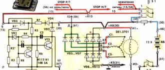
Motorcycle wiring diagram
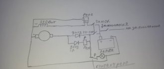
The proposed circuit is made of relays (RL), lamps (L), LEDs (D) and switches (S). Also in the diagram there are fuses marked (F). There is no repeater relay in the diagram, which is actually a pulse generator and a relay that, when turned on, closes and opens the contacts. Instead of repeater relays, a generator (repitor) is connected in the diagram, and the turn switch itself is labeled “REPIT.” The circuit is powered through the PW connection, at the same point there is a connection from the relay-regulator that supplies power from the generator. The ignition unit is not shown here. The D5-D9 LEDs are used to emulate the dashboard; when a particular consumer is turned on, the indication occurs on this panel. Low beam - LOW (L8), high beam - HIGH (L7), right side of repeaters - RIGHT (D1, D2), left side of repeaters - LEFT (D3, D4).
Example: As an example, I will give a real circuit
As you can see, nothing supernatural. This scheme is not fundamental and is made at the discretion of the manufacturer without following any generally accepted standards. To put it mildly, it is not convenient to read such a diagram, especially since the entire diagram is presented here as a whole with all the nodes and sensors in a heap. But having basic knowledge, you can navigate this scheme.
Below is a short video about how it works in real time. Let me immediately explain the following point: when you turn the ignition switch to the ACC position (accessories), power is supplied to the consumers. And in this circuit, for example, it is designed in such a way that when the power is turned on, the low beam lamp lights up, and the headlight turns on separately. This is rarely done anywhere, but at the moment, driving without low beams is a traffic violation. This saves one relay in the circuit. In principle, you can immediately turn on the marker when you turn the lock to the ACC position. Also, in many places an ignition switch with one position is used, then when you turn the key, power is supplied to both ACC and Ignition - the ignition.
The video below shows an emulation of the operation of the on-board network in real time.
Loading the player…
Connection diagram and connection of wires in the distribution box
As a rule, there is a distribution box with wires located on top of this switch. It can accommodate 3 cables:
- one goes down to the switch (Off)
- the second is the power coming from the switchboard (Gr.Osv)
- third - goes to the lamps in the bathroom (Light)
How to make the connection correctly, and what will be the connection diagram for all these wires in the junction box and on the fan itself? This can be schematically drawn as follows:
To connect all contacts, from the box to the ventilation installation site, you will need to lay another VVGnG-Ls 3*1.5mm2 cable.
The ends of the cable are stripped on both sides and signed.
- L-phase power
- T-phase for hood control via timer
- N-zero
There is no need to twist anything, just fit everything on the Wago clamps.
First, connect phase L to the main power cable coming from the switchboard.
Next, connect the neutral wires.
Please note that for the hood to operate correctly, a voltage of 220V must always be present at the terminals of the control board.
That is why one phase core of the cable is connected directly to the light switch.
That's why a three-core cable is used here. If you only have 2 wires going into your bathroom, you won’t be able to implement a circuit with a timer.
Phase T, which is supplied to the fan timer, is connected after the switch. That is, to the wire that goes to the lamps in the bathroom.
Thus, the ventilation is controlled through the light switch. All that remains is to correctly connect all the conductors on the fan itself.
Remove the protective decorative frame to get to the contacts.
There is a timer in the upper right corner. Immediately adjust it to the approximate operating time. Adjustment is carried out over a wide range - from 15 seconds to 45 minutes.
For some, it is turned almost to zero from the factory. As a result, the blades stop rotating immediately after the light is turned off.
People think that the hood is broken. Although it was enough to just tighten the screw.
Now connect the cables to the appropriate terminals:
- phase power conductor L - to the terminal with a similar marking
- fan timer phase - to the middle contact with the inscription T
- zero - to the remaining terminal N
Please note that if you have only 2 wires, phase and zero, then in order for the system to work at least in manual mode, you will have to make a jumper between terminals N and T.
Then the device will only work when the light keys are turned on and off. There can be no talk of any automation or time delay here.
Some other models are affected by the correct connection of the neutral - N and phase - L conductors. If your fan behaves in an unclear way and works or, on the contrary, refuses to work correctly, try swapping them.
Check the indicator light to see where exactly the phase is coming from and check again with the diagram indicated in the device passport.
Next, secure the fan and check its operation by turning the bathroom lights on and off.
Fastening is best done with glue or sealant.
Drilling holes for dowels is often problematic:
- or the holes are located close to the edge of the tile
- or there may be reinforcement in this place, and you will simply break your entire wall with a hammer drill
Here, as they say, depends on your luck.
Alfa 72cc moped wiring diagram with tachometer
There is alternating voltage on the white wire, which is immediately sent for rectification and stabilization. Current from the battery is supplied to the main circuits of the scooter. Brakes To adjust the front brake, a stop is installed on the brake pad disc. Before starting operation, check the tightness of all connections; presence of oil in the gearbox and fuel in the tank; correct adjustment of gear shifting mechanisms, clutch, brakes; tire air pressure; tension of the chain and wheel spokes; operation of lighting and signal devices.
If second gear does not engage, then the free end of the cable is small. To do this, you need to disengage the clutch, simultaneously reduce the engine speed and engage second gear. Problem identification is done using a multimeter. Starting the engine Before starting, after a long break in operation, engage first gear and roll the engine back and forth two or three times, squeezing the clutch. To open it, you need to remove the decorative plastic.
You should not drive for a long time in first gear, as the engine overheats, quickly wears out and overuses fuel. When lubricating, it is necessary to remove the old grease and wash the parts in kerosene.
Chinese mopeds
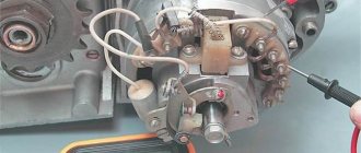
Since then it has been ready to launch. It goes directly to the spark plug, where it is converted into a spark. Ignition Circuit Components The ignition system is an important element in the operation of the entire scooter. Front fork 1 - bolt; 2 — upper bridge; 3 - spring; 4 — nylon bushing; 5 — fork frame; 6 — bushing; 7 — internal pipe; 8 — cover; 9 — bearing; 10 — protective washer; 11 - nut; 12 - lock nut. This abbreviation stands for Capacitor Discharge Ignition - ignition from a capacitor discharge.
Repair the camera according to the instructions included with the first aid kit. In this case, the wiring for the Delta moped is supplemented with several elements for connection. Sound signal The purpose of the sound horn is clear to everyone. During operation, the brake pads wear out, and then the brake mechanism cannot be adjusted using the above method.
Voltage is supplied only when the ignition switch is turned on. The remaining positions close the black and white wire from the ignition module to the ground of the scooter. You should not drive for a long time in first gear, as the engine overheats, quickly wears out and overuses fuel. Repair wiring on moped Alpha
Connection via two-button switch
Another suitable option is to connect the fan through the same light switch, but with two buttons.
Here the diagram will look like this:
In fact, your hood will sit regardless of the lighting. But for this, most likely you will have to change the single-key model to a two-key model. Plus pull the extra cable from the junction box down.
There are also pitfalls here. Firstly, do not mix up the phase connection on the switch contacts.
And this happens all the time.
Secondly, do not forget that through this switching device, it is the phase that must be broken, and not the zero. Even with the correct initial connection, over time the circuit may spontaneously change.
It is enough for some local electrician, in the general switchboard or entrance wiring, to accidentally swap two conductors L and N. And in your entire apartment the “polarity” will automatically change on all switches.
What will this mean? Well, for example, when you turn on only one fan with the second button, your LED lights in the toilet may blink, flash and go out.
The effect is quite well known for LED lamps.
Connect directly
If you initially abandoned junction boxes and use recessed socket boxes for switching, then the third connection diagram will be similar, and the differences here are practically not noticeable.
It’s just that all connections are made directly in the socket box. It can be done by crimping or using the same Vago clamps, if space allows.
There are also expensive, sophisticated models with remote controls.
They are connected in two ways:
- directly from the distribution box - forced manual shutdown is performed by a button on the fan itself
- via a separate light switch button
Differences in electrical wiring with and without a tachometer
Having a tachometer connected to the Alpha or Delta wiring allows you to monitor the intensity of your moped. Therefore, it is better to choose a speedometer with this device. Only a tachometer can measure such an indicator as the frequency of movement of various rotating parts. For example, the shaft. Without a tachometer, the dashboard will only display the instantaneous speed of your vehicle.
In the above diagram of the electrical connections of the Alpha and Delta mopeds, you can see that the tachometer is connected with yellow and green wires. If your model did not include this meter originally, you can improve your moped's wiring using the diagram provided.
There is also always the option of turning to professionals.
Installing motorcycle electrical connections, including connecting the starter, ignition system and other functional components, will require some experience. Therefore, if you are afraid of getting confused in pink, blue, yellow, green and black-red wires, it is better to entrust the modernization of the moped's electrical wiring to professional craftsmen.