The Czechoslovakian brand JAWA is well known in the USSR. Its two-wheeled motorcycles have become a revered and respected standard for motorcycle enthusiasts throughout the country. And this despite the fact that in our harsh conditions, Java 634 wiring and other electronic components often failed.
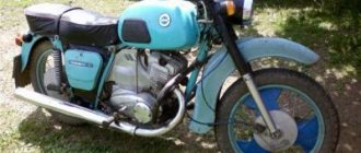
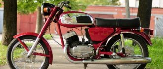
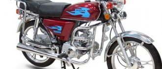
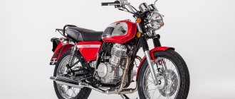
Legendary JAWA 350/634
Motorcycles of this brand first appeared in the USSR in 1973 and were sold at a fairly high price (the price started from 950 rubles, depending on the region). A couple of years later, instead of the “634th” model, which had 6V equipment, Czechoslovak motor builders proposed a new generation - “638”, transferred to more promising 12-volt equipment.
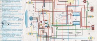
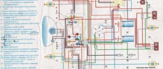
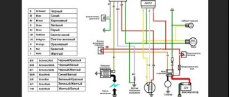
Note! It should be noted that there was a shortage of spare parts for motorcycles. Even a detailed wiring diagram for the Java 634 (shown in the photo below) was considered a great success when buying a motorcycle second-hand.
Color scheme for the 6B version of the JAWA motorcycle
Operational Features
It was the motorcycle in our country that became a clear confirmation that a two-wheeled vehicle is truly a means of transportation.
The owners and their “iron horses” could be found everywhere:
- In the forest thicket;
- In the mountains;
- On city highways;
- In the rural outback;
- At sports competitions, etc.
On a JAWA motorcycle you could easily travel 1000 km from home.
Its endurance and reliability on the longest routes contributed to such a high popularity of the brand as a whole. Even the resale of a 5-year-old copy brought the former owner at least 500 rubles.
For reference: Purchasing new domestic two-wheeled motorcycles cost more modest sums for the family budget. The shortage of spare parts, missing instructions and minor breakdowns did not stop me from buying my dream motorcycle.
However, difficulties with parts and a simple design contributed to the fact that owners serviced the motorcycles with their own hands in a variety of places:
- In private garages;
- In the back rooms;
- On the balconies;
- In apartments, etc.
The lack of a garage has never been a hindrance to a true motorcycle enthusiast
Fantastic popularity
In the 70s, the domestic industry also did not stand still and offered consumers a number of motorcycle models (see also the article on the Ural motorcycle wiring diagram).
However:
- in terms of the ratio of speed qualities and comfort;
- and also combined with reliability and ease of DIY maintenance;
motorcycles from Czechoslovakia had no equal. Statistics eloquently testify to this: in 1976, more than 1,000,000 owners of a JAWA family motorcycle were recorded in the country.
Corporate photo of the Sporting Goods chain, which sold JAWA motorcycles in the USSR
Such enormous popularity was explained quite simply - the lack of technical ability for citizens to travel:
- Even with the funds to purchase, a passenger car had to wait in line for the suffering for several years;
- Domestic motorcycles were characterized by low reliability and were not suitable for comfortable trips of many kilometers (see also the details of the IZH Planet 5 wiring diagram).
For reference: the Czech-made motorcycle received its index “350” from an engine whose volume was 350 cubic meters. cm. The two-cylinder power unit had a power of 12 to 18 hp. depending on the year of manufacture.
Motorcycle electrical equipment
Despite the high build quality and durability of the main components and assemblies, the technical condition of the motorcycle had to be constantly monitored.
In particular, regular maintenance was required:
- Battery;
- Ignition systems;
- Fuel supply systems;
- Lubrication systems.
The manufacturer clearly indicated in the documentation the components that require constant attention
Battery
Motorcycles made in Czechoslovakia were equipped with a proprietary TREPCHA 6A5 battery. Its service boiled down to:
- Checking the electrolyte level in each cell;
- Checking its density (nominal value - 1.26 g/cm3);
- Charging the battery when the discharge at the terminals decreases below the permissible values (when fully charged, the voltage is 7.8-8.1 volts). The battery is charged with a current of 0.6 A.
The TREPCHA 6A5 battery was installed under the seat
Wiring
The Java 634 6v wiring diagram also required close attention from the owners.
In particular:
- All wires must be inspected from time to time, and if the insulation is broken or damaged, repaired or replaced.
- Check the spark plug wire. If cracks appeared in the insulation or on the protective caps, the wire should be replaced.
For reference: dirt accumulated in the insulation cracks and served as a bridge for current leakage, which affected the sparking of the ignition system.
- Check the operation of the brake light switch, the drive of which is located quite low to the road surface.
- Check the condition of the 15 A fuse contacts;
- Check the operation of the headlight.
The motorcycle wires had to be carefully monitored
Motorcycle Java.
Technical characteristics, operation and repair, parts catalog. >> ELECTRICAL EQUIPMENT — Electrical equipment diagrams. Ignition. Contents :: Next >>
ELECTRICAL EQUIPMENT
Electrical circuit diagrams
The electrical equipment of Java motorcycles includes current sources, an ignition system and a lighting and alarm system.
Motorcycles are usually equipped with a dynamo-battery electrical system. Their current sources are a battery and a generator. The rated voltage in the electrical system is 6 V or 12 V.
Ignition
Position I (Fig. 89) corresponds to parking the motorcycle. The key is inserted or not inserted. The current from the battery through fuse 21 (see Fig. 85), terminal 30/51 of the ignition switch and switch 23 flows to brake light lamp 2, and through the second terminal 30/51 to sound signal 13. When the rear wheel is braked, the switch is activated 23 and brake light lamp 2 lights up, and when you press button 12, the circuit connecting the sound signal to ground is closed and it turns on. The contacts of the reverse current relay (regulator relay) are open, and no current flows to the generator.
Position II (Fig. 89) is used when driving during the day. The key is inserted and turned to the right. Terminals 30/51 and 15 are connected, and the current from the battery goes to the ignition coil 14 (see Fig. 85) and to the neutral indicator lamp 6 and the generator control lamp 7. This lamp is connected in parallel with the reverse current relay contacts and illuminates when they are open, indicating that power is being supplied from the battery.
With the ignition key in this position, the engine can be started. At a crankshaft speed of approximately 1500 per minute, the generator voltage reaches 6 V, and at the moment when it becomes greater than that of the battery, the contacts of the reverse current relay will close, as a result of which the current from the generator will flow to the electrical system (suitable for the battery the current will charge it).
The control lamp will go out because the resistance of its filament is greater than the resistance of the relay contacts.
Position III (Fig. 89) is activated to start the engine without a battery.
The key is turned to the left. Terminals 61 and 15 are connected. Current from the generator goes directly to the ignition coil. This position is used when the battery is faulty or missing. To start the engine, engage second gear, disengage the clutch and accelerate the motorcycle. When it gains sufficient speed, engage the clutch and, if the engine does not immediately start working, continue to increase the speed of the motorcycle. As a rule, the engine of a properly tuned motorcycle starts very quickly.
Position IV corresponds to driving at night on an illuminated road.
The key is inserted, the light switch is turned to the first position. In this case, terminals 30/51 and 58 of the ignition switch are connected. Power from the battery or generator is supplied to the taillight lamp and to lamps 18 (see Fig. 85) for the speedometer lighting and lamp 11. Such lighting is used at night when parking or driving on well-lit roads.
Position V (Fig. 89) is used when driving at night on an unlit road. The key is inserted and the light switch is turned to position II. Terminals 30/51, 58 and 56 are closed. In addition to the consumers turned on when the key is set to position IV, current from terminal 56 flows through switch 8 (see Fig. 85) to lamp 10 of headlight 9.
The electrical systems of other motorcycles operate similarly to the circuit discussed above.
Knowing the electrical circuit diagram of a motorcycle makes it easier to find a fault.
Rice. 85. Motorcycle electrical circuit diagrams: a - “Java-250” model 354/04; b — “Java-350” model 354/04; c - “Java-250” models 559/02, 559/04, 559/07; d — “Java-350” models 354/06, 360/00 1 — rear light; 2 — brake light lamp (6 V, 15 W); 3 — license plate lamp (6 V, 5 W); 4 - couplings; 5 - central switch with ignition switch; 6 — neutral gear indicator lamp (6 V, 1.5 W); 7 — generator warning lamp; 8 — low and high beam switch; 9 - headlight; 10 — low and high beam lamp (6 V; 25 + 25 W); 11 — parking (city) light lamp (6 V; 1.5 W); 12 — button to turn on the sound signal; 13 — sound signal; 14 — ignition coil; 15 - high voltage wire; 16 — spark plug; 17 — contact for switching on the neutral indicator lamp; 18 — speedometer lighting lamps; 19 - generator; 20 — relay-regulator; 21 - fuse (15 a); 22 - battery; 23 - brake light switch. Wire color symbols: B - white; F - yellow; 3 - green; K - red; C - blue; H - black
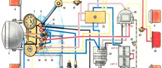
Rice. 86. Electrical diagram of the Java-638 motorcycle: 1 - turn signal relay; 2 — emergency engine stop switch; 3 - generator (12 V); 4 - excitation winding; 5 — brushes; 6 - stator windings; 7 — ignition breaker contacts; 9 — neutral gear lamp switch; 10 - rectifier; 11 - battery; 12 - fuse; 13 — relay for turning on the generator operation indicator lamp; 14 - relay-voltage regulator; 15 — rear direction indicator lights; 16 — rear light; 17 — lamp (21 W) brake light; 18 — backlight lamps (4 W); 19- tips of high voltage wires; 20 — spark plugs; 21 — ignition coils; 22 — brake light switch; 23 — switch for direction indicators, low-high beam, horn switch; 24 - sound signal; 25 — control lamp for neutral in the gearbox; 26 — control lamp for generator operation; 27 — ignition switch; 28 — front direction indicator lights; 29, 33 — speedometer illumination lamp; 30 — parking light lamp; 31 — main light lamp; 32 - headlight; 34 — control lamp for turning on the high beam; 35 - indicator lamp for direction indicators.
Rice. 87. Electrical diagram of the Java-50″ motorcycle, type “634”: 1 — front direction indicators with 6 V, 21 W lamps; 2 — tachometer scale illumination lamp 6 V, 2 W; 3 — headlight lamp 6 V, 30/35 W; 4 — headlight parking light lamp 6 V, 4 W; 5 — speedometer scale illumination lamp 6 V, 2 W; 6 — emergency ignition switch; 7 — relay-interrupter of direction indicators; 8 - single connectors; 9- high beam indicator lamp 6 V, 2 W (blue); 10 — indicator lamp 6 V, 2 W (orange); 11 — ignition switch; 12-control lamp neutral 6 V, 2 W (green); 15 — indicator lamp for generator operation 6 V, 2 W (red); 14 — detachable block; 15 — sound signal; 16 — block of light switches, direction indicators with sound and light signal buttons; 17 - generator 6 V, 75 W; 18 — relay regulator; 19 — brake light switch; 20 — neutral control lamp switch; 21 — ignition coils; 22 - battery 6 V, 14 Ah; 23 — rear direction indicators with lamps 6V, 15W (brake-stop light) and 6V, 2W (parking light).
Rice. 88. Schematic diagram of the electrical equipment of motorcycles “Java-250” models 559/02, 559/04, 559/07 and “Java-350” models 354/06, 360/00: 1 - generator; 2 - excitation winding; 3 - additional resistor; 4 — voltage regulator spring; 5 - reverse current relay winding; 6 — contact of the second stage of adjustment; 7 - movable contact of the voltage regulator; 8 — contact of the first stage of regulation; 9 - yoke; 10 - voltage regulator winding; 11 - movable contact of reverse current relay; 12 - fixed contact of the reverse current relay; 13 - fuse (15 a); 14 — battery (6 V); 15 — sound signal; 16 — signal activation button; 17 — brake light lamp; 18 — central switch; 19 — brake light switch; 20 — switch for high and low beam; 21 — high and low beam lamp; 22 — lamps for illuminating the speedometer scale; 23 — parking (city) headlight lamp; 24 — license plate lamp; 25 — switch (contact) of the neutral gear lamp; 26 — generator warning lamp; 27 — neutral gear lamp; 28 — primary winding of the ignition coil; 29 — capacitor (260 V; 0.27 μF); 30 - secondary winding of the ignition coil; 31 — breaker cam; 32 — breaker contacts; 33 - spark plug. The dashed line outlines the chains related to the Java-350 motorcycle.
Rice. 89. Positions of the ignition key and light switch and the corresponding circuit connections in the central switch of the Java-250 motorcycle model 559/07: I - the key is inserted (or not inserted); II - the key is turned to the right - the ignition is on; III - the key is turned to the left - starting the engine without a battery; IV - the switch is turned to the right, in the first position - the headlight parking light and license plate lighting are turned on; V - the switch is turned to the right, in the second position - the headlight lamp is additionally turned on
What to do next?
Most likely, the ignition you assembled from a Java 634 scooter is rough and consists of twists, which is why you should replace them with normal terminals and twist the wires into braids. There is only a small matter left to do - completely replace all the remaining electrical elements, starting from the dashboard and ending with the head lighting and turn signals. Fortunately, now you have full 12 volts, so you can replace everything with spare parts from older models. On the other hand, 12 volts open up the opportunity to install almost any modern turn signal, high-quality lighting and many other useful devices such as a charger for a smartphone or an on-board audio system.
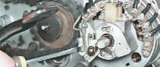
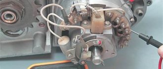
We install the ignition from the scooter to Java
First of all, we check whether our adapter plate is suitable, if so, then we attach it, install the rotor and stator. The latter should fit completely into the rotor; for convenience, we adjust the distance with washers. We install the sensor and make sure that everything rotates with a reserve and does not touch anything.
Now we need to modify the rotor. From the existing mark on the rotor, after 180 degrees we install a new mark. To maintain the accuracy of the procedure, it is best to use special devices that measure the angle of rotation; you can also use a lathe for this. We solder or weld the mark, obtaining 100% reliability of the unit.
What will you need?
To install the ignition from a scooter in Java, we will need a specific conversion kit. First of all, there is the generator itself; there are two models to choose from. The simpler QMB-139 will perform all the necessary functions, but problems may arise with the light at night, since the winding for the head light is rather weak and will greatly depend on the speed. If this parameter is important to you, then choose a stator from the QMI-157 or 152QMI model - they will be sufficient to achieve your goals.
You will also need an ignition coil with two terminals, here again there is plenty to choose from. For our purposes, motor coils ZMZ-406 or from Oka are suitable.
You will need a 12 volt battery. We don't need a new one; any used motorcycle or new Chinese battery will do. Its role is to smooth out voltage drops in the turn signal and stop signal circuits.
Also, do not forget about the set of wires/terminals. It is better to take the latter from Japanese scooters.
The last item is the adapter plate. Alas, it cannot be found on sale, but kind people have prepared the exact drawings presented below, according to which you can assemble your own adapter plate or order it. The thickness of the metal is 4 mm, this is an important parameter, because if you make the plate larger or smaller, some elements of the system may not fit or work incorrectly.
INSTALLATION OF BSZ
To do this, you need to prepare the following in advance:
- tools: screwdrivers, pliers, hammer, anvil, multimeter (preferably electronic), narrow ruler (up to 10mm wide) or calipers, file and needle files
— parts: switch (VAZ-2108), Hall sensor, connecting wire harness for them (ready-made for sale), two-terminal ignition coil from Gazelle or Oka, modulator (butterfly is made of magnetic metal 0.7-1 mm thick according to the drawing below) high-voltage wires (armored wires) high power (preferably silicone)
1.Initial stage
First, let's make a modulator if you haven't already made one. The easiest way to do this is to print out the drawing in real size (the dimensions of the drawing correspond to real measurements), stick the printout on a metal plate and cut out the modulator along the contours of the drawing. ATTENTION. Millimeter precision is important here! So no “glaring” can be allowed here. The edges of the modulator must be processed with a file so that there are no nicks or burrs.
2.Dismantling
— Disconnect the high-voltage wires from the spark plugs.
— Disconnect the inductor wires from the ignition coils
— Remove the ignition coils along with the high-voltage wires (we won’t need this anymore)
— Disconnect the capacitors from the breaker contacts
— Disconnect the inductor wires from the breaker contacts
— Remove the contacts from the ignition plate
— Unscrew all the screws from the ignition plate and remove it from the generator
3.Preparation
— Place the anvil on a flat surface
- Place the ignition plate on the anvil and smooth out all the bends with a hammer, and remove the breaker pins with pliers
— Unscrew the generator rotor bolt
4.Installation
— Hang the 2-pin ignition coil in a convenient place under the tank
— Connect wires 1 and 4 of the switch to the coil as shown in the diagram, as well as high-voltage wires to the spark plugs (ATTENTION: DO NOT USE HIGH-VOLTAGE WIRES FROM YOUR OLD COILS. FOR ELECTRONIC IGNITION YOU NEED POWERFUL WIRES, PREFERABLY SILICONE, PRO AVAILABLE AT ANY CAR STORE !)
— Screw the modulator to the rotor with a standard armature bolt
— Attach the Hall sensor to the plate as shown in the photo
— Secure the switch in a place convenient for you (it is recommended to install it on the right cover of the air cleaner directly under the facing cover)
— Lay the connecting wires of the switch and the DC and connect to the switch and the DC
— Ground wire 2 of the switch to the motorcycle frame (do not ground to the tank!)
5.Adjusting the ignition timing (IPA)
5.1. Set the left piston to top dead center, and using a ruler (or caliper) move the piston back 3mm
5.2. Loosen the generator bolt securing the modulator (ATTENTION DO NOT ALLOW THE SMALLEST ROLL OF THE CRANKSHAFT.)
5.3. Connect the multimeter like this: the red clamp to the green wire of the hall sensor (at the input to the sensor from the green wire, you need to move the white heat shrink and gain access to the bare wire), and connect the black clamp of the multimeter to ground (for example, to the engine crankcase)
5.4. Set the multimeter to read voltage in the range of 0-20 volts
5.5. Turn on the ignition (the multimeter should show a value either equal to or close to zero)
Types of BSZ
There are two types of BSZ:
— Single-channel (one Hall sensor, two-lobe modulator, one switch, one two-terminal ignition coil operating on two cylinders at once)
— Two-channel (two Hall sensors, one, or better yet two, modulator lobe, two switches, two ignition coils, one for each cylinder)
It is preferable to install a single-channel system, since it will be more stable, because here you do not have to adjust each cylinder (which you have to do at KSZ); here, if the modulator is properly made, then only one cylinder is adjusted. Also, in a single-channel one, fewer wires are used, its parts take up less space, and energy consumption is lower (which is very important for 6-volt generators)
There are many people who like to “get confused” who install a two-channel one, shouting at the same time that this way they can configure it more accurately, etc. I assure you that these are unnecessary hassles, and there will be no accuracy here (why is indicated above)
Spark plug. I said above that spark plugs “live” longer, which begs the question “Why?”
Actually the answer is simple. If you decide to install a single-channel BSZ (or a two-channel one with a two-lobe modulator), then this is what will happen:
When igniting in one cylinder, in the other, a spark will also strike at BDC, since it strikes simultaneously on both spark plugs, that is, spark twice per revolution on each spark plug.