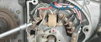
They all go into a big black rope.
The relay-regulator itself is attached to the metal base of the scooter in order to reduce the heating of the relay radiator during operation.
There are two main coils: under the steering wheel and next to the battery, under the shield. The principle of operation of the alpha/delta moped engine
How to check, replace Checking is carried out using a multimeter. This is what the relay regulator looks like on a scooter.
Also, you cannot replace lamps with more powerful ones. It is also prohibited to use headlight lamps on a moped that exceed the power specified in the technical documentation.
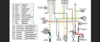
Relay regulator 5. Tip: The wiring of the Alpha moped especially suffers from harsh climates, since its insulation is made of cheap plastic. Another electrical connection diagram from the spare parts catalog for the Delta. Features of electrical equipment. The wiring for the Delta and all electrical equipment is quite traditional. How to read a diagram of a Yamasaki, Alpha, Delta moped
We recommend reading:
Another electrical connection diagram from the spare parts catalog for the Delta. Features of electrical equipment. The wiring for the Delta and all electrical equipment is quite traditional. However, this is exactly what will help toughen the motorcycle owner in the face of eternal breakdowns and make him a real ace in the electricity of his motorcycle.
There are 5 wires connected to the CDI module.
Generators can also be different: 2-coil tachometer with two wires, 6-coil tachometer with three wires. As a result, the relay regulators will differ.
We recommend reading:. Wiring diagram for an Alpha moped with an electronic tachometer. The same simple operation of the moped also contributes to its popularity.
Wiring on an Alpha moped with an electronic switch in the ignition system For reference: electronic ignition ensures trouble-free engine starting and stable operation in all operating modes.
Also, you cannot replace lamps with more powerful ones.
The starting relay receives a thick red wire from the positive terminal of the battery. There are models where the motorcycle is completely converted to direct current, but these are old models and they are quite rare. ALPHA WIRING! ALPHA 110! MOPEDA WIRING
Homemade Voltage Regulator
Good day to all! I didn’t think that I would decide to write, but chance forced me to do it... The essence is a homemade regulator! I personally soldered about 10 pieces with a circuit on 3 diode bridges. I installed it on a SUZUKI GSX-R600. The first one was soldered and then contacted the Man from Ukraine, who either came up with this scheme or is his follower on the first line. They rechecked everything and it worked, but it got terribly hot. Or rather, it was noticeably warming up. But it worked. He was outwardly unprepossessing, which I didn’t like. Then I collected more in different variations, but they all worked strangely. Either the voltage was unstable at 14.2, or it generally dropped to 12.5 at higher speeds. I began to decide the decision. Assembled from three parts - bridges, triacs and resistances, control, so that you can find the error and change it, understanding the vibrations of the assembly. It all boiled down to the fact that, with a high degree of probability, the principle of the work depended on the state of the main circuit itself. Whether there is xenon or not, speed, wiring condition - rain, dry, the influence of the motorcycle's electronic systems on the regulator... In the end, it worked, but not correctly. I contacted people who have been doing this for 8-10 years. And not just, but programmed and adapted. In addition, electronics engineers who understand the permissibility of the parameters and speed of operation of the elements, amperage and power... RESULT: I bought a 40 amp rede-regulator from a high-speed motorcycle (BMW S1000RR superbike - standardly installed on DUCATI, KAWASAKI, etc. with a volume of 800-1000 and up to 1400). It cost 2700 rubles. Put. At lower levels it is generally cold, at 4000-5000 rpm, until you can go deaf in the garage, it warms up a little. This is without low beam. Work within 14.2-13.9. At high speeds the readings in the circuit, in the area of the lighting load, increase slightly - up to 14.3-14.4. The neighbor added. The characteristics have not changed. On the battery - 14.06-14.2. Added distant. The voltage just dropped to 12.8 in the circuit (but this is + 2 lamps at 12 V, 55W). It is possible that this relay is a little weak in current strength for my motor, but it works properly and adequately. Everything on the battery is still stable, 13.7-14.2. The battery is new! This is a shunt-type relay-regulator - accepted by the equipment manufacturer as standard (there is also a non-shunt type - more energy-heat adequate)! THINK, CHOOSE! For simple motorcycles (or analog choppers) and scooters without serious electronics, perhaps a homemade relay is relevant, but if you have a SUPER BIKE or SPORT BIKE! Have mercy on your nerves and your faithful friend! This is my advice to you! — A FACT FROM PERSONAL EXPERIENCE!
Answer
Ignition circuit elements.
Electronic tachometer on the dashboard.
When the turn signals are on, it makes characteristic clicks with a frequency of about 1 Hz. Also, you cannot replace lamps with more powerful ones. Due to the electronic circuit of the regulator, the voltage on this wire is converted into a pulsating one, and is supplied to powerful current consumers - low and high beam lamps, as well as dashboard backlight lamps, there may be several of them.
This is what the relay regulator looks like on a scooter.
Due to its primitive circuitry, the relay-regulator often fails. Basic Concepts In order to understand wiring, you need to understand a little about the types of current. The starting relay receives a thick red wire from the positive terminal of the battery. The alternating voltage is removed from the white wire and supplied to the relay regulator for subsequent straightening and stabilization.
The start relay is located on the right side of the scooter frame. This is an ordinary key switch that switches the positive voltage from the relay-turns the gray wire to the lamps. There are three wires coming from the sensor. The fuel level indicator, tachometer, sound signal, turn relay, and ignition circuit are also ready for operation.
Experienced owners, after purchase, replace it with rubber-insulated wiring. Also, you cannot replace lamps with more powerful ones. The toggle switch must be powerful enough, because the entire electrical circuit of the scooter is, in fact, switched through the ignition switch. Wiring Operation The large black wire connects: 2 yellow ones, green and red, where direct current flows. Valuable tips It is no secret that wire insulation is made of cheap plastic and it is better to replace the insulation with rubber before it crumbles after a few rains.
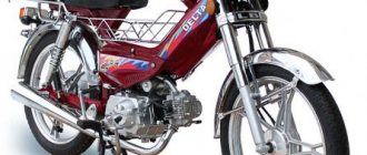
This can be easily fixed, but the wire will have to be shortened by 0.5 - 1 cm. But if we “walk” along the high-voltage wire from the ignition coil, the wire will lead us straight to the spark plug cap. Lamp power 25W, supply voltage 12V. Ignition coil 2. Moreover, which is typical, a fairly large number of beginners decide to buy a two-wheeled vehicle, choosing Alpha mopeds.
Therefore, you should not pull the wire too hard, otherwise you can pull the wire out of the cap. Structurally, the ignition coil is located next to the start relay. Therefore, if at idle the lamp shines very brightly, and not at full intensity, then it is better to turn it off and check the relay regulator. Alpha 72 (Voltage Regulator)
MY MOTORCYCLE
Since I created a comprehensive site, I want to devote a little time to Chinese mopeds, or rather, today we will touch on the voltage relay regulator of Viper, Delta, Alfa mopeds. I found the relevant information and want to share it with you.
The wiring of the Chinese mopeds Viper, Delta, Alfa is very interesting. The ignition is separate, the lighting is separate, which is similar in many other scooters and motorcycles. But the lighting itself is very confusing. We have two lighting branches, one is the electricity from the generator, the other is from the battery. At the same time, the generator itself also powers the battery. And to connect these two wires, a voltage regulator relay is used.
It is designed to rectify the voltage and stabilize it so that the battery and lighting do not receive more current than usual (remember how the light bulbs burned in old motorcycles, all because there was no stabilizer). This is the main task of this voltage regulator relay. And if you look at the number of wires of such a relay-regulator, we see four of them. One, green, is the ground (in scooters the ground is often green), the other is red, it goes to the battery. The third and fourth come from the generator. And here you can get confused. Each wire comes with a voltage of 12 V, but if you look closely at the structure of the generator, it is clear that one has a slightly lower voltage, this is done for the sake of relativity, so that the relay can compare two voltages. It is important here not to confuse the wires, since in some scooters they are marked with white and yellow colors, while in others there are two white ones. But they are not the same, they cannot be confused.
By the way, if you look at the wiring in the Viper Active moped, the relay-regulator has a pink wire instead of a white one. Therefore, remember, when comparing wires or other relay regulators, white is equivalent to pink. There are other voltage regulator relays, where the colors are even more changed, but more about that later.
So, the purpose of the regulator relay has been explained. Voltage relay regulators for Viper, Alfa, Delta mopeds are interchangeable. They can be easily changed, moreover, spare parts for the Viper moped are hard to find, and here many will have to take a voltage regulator relay from an Alfa or Delta scooter, since they cannot find the “original” one. The difference here will be in the connections, you will have to resolder, and as has already been mentioned, in Viper they often use pink instead of white.
Likewise, generators can be changed. The difference between them is the number of wires wound and the colors. Also, the connection is different when the wires come out, so here you will have to resolder or simply connect without a “mother-father”.
In Viper mopeds, the voltage regulator relay is located under the seat. In order not to confuse it with another wiring element, we are looking for a spare part with ribs, since the relay-regulator requires cooling and they will definitely be on the metal case. But the sizes may be different. This relay is very similar to the Minsk or Voskhod motorcycle switch. That's all for now...
source Blog-Moto. RU
How to check the voltage regulator of a scooter?
To check, you need to stock up on a multimeter that has a voltmeter function. It is needed to measure the voltage at the output of the voltage regulator.
To measure the voltage, you first need to get to your destination. To do this you need to remove the front fairing. As a rule, it is fastened with several nuts and rivets (for example, Honda dio has 3 nuts and 4 rivets). We remove the fairing carefully, it is easy to damage. There we need to find a small box in which there are 4 outputs (some scooters have 5 outputs). The outputs have the following colors: green, red, yellow and white.
In order to measure the voltage, the scooter must first stabilize in operation, that is, the idle speed must be stable. You can put it on the step, start it and wait for it to stabilize. If the scooter does not start or does not hold idle, then read the article: the scooter does not hold idle. If everything is fine, then you need to measure the voltage between the red and green wires. We set our measuring device to 20V, constant voltage measurement mode. If the voltage is within 14.6 - 14.8 then this is the normal voltage of the relay regulator . If the regulator is faulty, then this value can fluctuate even by 5V or more in any direction. If the value is less than 14.5V, or exceeds 15V, then the regulator is faulty.
Now you need to check the voltage supplied to the lighting. Since alternating voltage is supplied there, we set our multimeter to measure alternating voltage 20V. To measure the voltage supplied to the lighting, you need to measure it between the green and yellow wires. As a rule, the norm for lighting is a voltage of 12 volts; most incandescent light bulbs are designed for this voltage. Allowed + – 0.5 volts. Do not forget that the scooter operates at idle and if you add speed, the voltage will rise, but it is not permissible for the voltage on the regulator to rise to 13+ volts. If the regulator is faulty, the voltage may rise higher. For example, up to 15-16V, but even 13 volts of voltage is harmful for incandescent light bulbs. The regulator is clearly faulty. Especially considering that this is at idle engine speed.
If you see that the voltage regulator is faulty, you need to urgently replace it. Otherwise, very soon other devices will be added to it that simply could not withstand the high voltage.
A 4t scooter voltage regulator relay can be bought for 500 rubles.
If you don’t understand what and how to check, or have additional questions, you can ask them in the comments or find the answer in the video: