Installation diagram of a driven clutch disc from Tavria on the Dnepr
It would be worth starting with the question WHY is it needed? I think so-so that the advantages of a driven tavrodisk are the presence of a spring damper. Its (damper) location “before” the gearbox smooths out torsional vibrations on the shafts of the gearbox itself, which is not actually observed if only a rubber damper is installed “after” the gearbox. I think that with this scheme the box will work a little longer. Well, I’ll emphasize once again that this is not “nuno”, but “mono”. That is, the description is intended for those who like to get technical.
Well, Negara gave me a disc from the brand a year ago :)) so this disc was collecting dust under the bed... But there always comes a moment when a person asks himself: “How much can you?”
I, myself, am an ACAD fan. Really. The main toy in the computer :))) And the only one :)))
So I decided to sort out all this Tavriganskaya crap and draw it properly.
But let's take things in order.
Our standard clutch looks something like this (springs and screws are not shown):
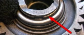
Somehow something started ringing in my engine at very low speeds and with the clutch depressed. The book didn’t tell me anything about this, except that you can drive further, and if necessary, check it out. Well, on occasion, on occasion. It turned out that there was nothing catastrophic there. The middle steel drive disc begins to ring when the holes on it become slightly broken. And this happens very soon.
Let's go further. All this talk to me about installing a disk from Tavria... I couldn’t find any proper information, so I decided to draw everything myself.
Let's first consider the disc itself from the brand.
It consists of two plates that hold springs; a central plate that “hangs” on these springs; a splined bushing, which is cleverly pressed into the central disk; disc-bracket for the friction discs themselves; a centering plastic sleeve (purple in the picture); washers with whiskers and a spring washer. All THIS is assembled with rivets.
Let's get started.
The spline bushing is pressed out of the central disk with three blows of a hammer. We give the plate itself to the turner to grind the inner hole (the teeth must be cut off).
Next, we remove the bushings from our original MT driven disks, cutting off eight rivets with a grinder.
These bushings need to be machined. We also give them to the turner, showing the following diagram:
They need to be machined one and a half millimeters, or a little less, from the chamfer side of the holes, and the diameter must be such that they are pressed into the central disk.
The diagram (right) also shows the new centering sleeve. It needs to be made of duralumin or bronze so that it is pressed onto the MT spline bushing.
Then it gets more interesting. The MT bushings must not only be pressed in, but also secured in the central plate. To do this, in the latter we will need to drill eight holes with a diameter of 5 mm. The plate is basically calcined. We take a victorious drill and remove the side cutting edge on it. Next, using our machined bushings as a template and as a guide for the drill, slowly pouring oil on us, we drill the central plate at very low speeds. Because the holes hit the edge of the metal, the drills experience extreme side load. I ruined four pobedit drills :))))…
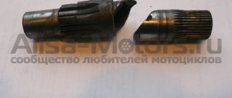
The photo shows the actual central plate on which we drilled and broke :)), and turned MT bushings.
When you mount the bushings into the central disk, pay attention to the fact that they need to be turned so that the holes of the two bushings and their splines coincide.
Drilled? Now remove the chamfers on the bushings for the rivets, and rivet the bushings with the central disk. Next you need to remove a 1x45 degree chamfer from the “inner” side on one of the spring holder plates to install the centering sleeve. All that remains is to press on the centering sleeve itself and put it all together.
Well... We made the driven disk itself.
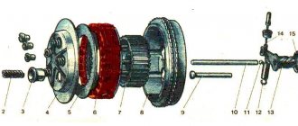
Let's see in the diagram how this is all installed.
On the left is a sectional diagram of the modified clutch, on the right - the standard clutch.
The sequence of discs is: release, intermediate drive from the standard set, driven (already T-type) and drive, which is screwed to the flywheel. The driven disk may rest against the box (as in the case of using the Moskvich one), so you may have to shorten the flywheel pins. Or you can simply put another intermediate drive between the driven (already branded) and the drive, which is screwed to the flywheel. But this will make the whole set heavier, which may affect the dynamics.
I’ll say right away that I sharpened the flywheel. I cut off the outer shell and increased the groove “around” the fastening bolt. This lightened the flywheel by one and a half kilograms.
- Before shortening the flywheel pins, ALWAYS make sure that the gearbox drive shaft is long enough for such a disc offset.
If you intend to install a starter, check whether there is room for its crown.
By the way, sometimes there is talk about installing a Moskvich disk (401 or 408), in which the splined bushing matches the teeth one to one with the MTshnoy. But they also say that its damper works “in the wrong direction,” and therefore, with such a disk, the gearbox shafts fly, in the absence of a rubber washer after the box. But it is impossible to turn the disk over due to its specific dimensions. I haven't tested it in metal. That's just what they said.
Well? This is actually the crown of the fairy tale. And whoever listened, there will be photos a little later :))).
author SerDUKE [email protected] www.MOTO.kiev.ua
comments:
RuS: The Moskvich disk works in both directions! Judge for yourself, first there is a jerk for engine acceleration and then for engine braking! Which jerks are there more? the box flies from both of these jerks! He's just tough! I’ll also ask my friends what’s good about it. Because they still prefer to leave the rubber coupling even when installing a clutch from a Muscovite!
Kolyan: 408 works in both directions. rigidity, yes, worse than beastly. But this is a plus when the engine is pressed. the clutch is left because there is nothing to replace it with, the two-cardanka costs money. but it’s not easy to install, its springs protrude beyond the ferrido plane, so you have to put an intermediate one on the pressure plate.
RuS: Ours put two crosspieces on the cardan and coupling! The clutch really changes on the street every 1000-2000 km! Can't withstand loads!
Awl: The disc from M 408 fits one to one in diameter and spline (that’s what I’m going to put in), but it’s thick, it’s an infection - not only the springs extend beyond the ferodo plane, but also the splined bushing is incredibly thick - most likely you won’t be able to get by with just one intermediate one...
Auto-Oleg: And I left the MT clutch and set it to 6!!! stepped gearbox (all six forward and on needle bearings), I removed the clutch and installed two crosspieces in front of the cardan and at the rear and I feel fine. The first gear is average between 1st and 2nd standard. The sixth accelerated ratio is 0.92. And also an accelerated axle with wheels of 18. Boosted the engine. Pistons of 79. Oil filter. Non-contact ignition, Delort carburetors. Disc brakes. The whole thing is in plastic. In the style of a bike. who knows the mountain from Petrovka to Shulyavskaya in Kyiv and on the ascent to the 6th it also picks up speed!!! And who is interested in the device, it was published in “Signal”, it seems for the year 2000 or 99, it seems the 7th month.
SerDUKE: Yesterday I tried on the Tauride disc. Not everything is as stated in the article: A release disk is installed, then a standard middle drive disk, then a converted driven disk, with springs to the box, then the drive disk is screwed to the flywheel. It seems that no changes are needed on the flywheel (such as the supposed bushings for the springs or shortening the pins on the flywheel). You just need to have a converted disk.
How to properly tension the clutch cable.
I searched the forum, but didn’t find or didn’t notice similar questions. A question has appeared. How to properly tension the clutch cable so as not to overtighten it or become too weak. Who exhibits what?
2↑ Reply from Ural*4uK 04/22/2013 15:32:06
- From: Russia, Bryansk region, Mglin
- Registered: 03-03-2012
- Messages: 1 451
- Reputation: 39
- Motorcycle: Ural IMZ 8103 with sidecar
Re: How to properly tension the clutch cable.
at the end of the cable, above the box, there are adjusting nuts - you will understand how and where to turn. and on the steering wheel (on the clutch lever) you make a free play of 2-3 mm and that’s it
3↑ Reply from Student 04/22/2013 15:42:49
- From: Engels
- Registered: 11-04-2013
- Messages: 267
- Reputation: 3
- Motorcycle: Dnepr MT 10, Dnepr MT 11
Re: How to properly tension the clutch cable.
What are the signs that the cable is too tight? Or do I need to tighten it a turn?
4↑ Reply from PATRIOT 04/22/2013 16:25:59
- From: Krasnodar region, Krasnodar
- Registered: 18-02-2011
- Messages: 3 148
- Reputation: 180
- Motorcycle: No. Next will be the K750!
Re: How to properly tension the clutch cable.
at the end of the cable, above the box, there are adjusting nuts - you will understand how and where to turn. and on the steering wheel (on the clutch lever) you make a free play of 2-3 mm and that’s it
What another 2-3mm. If I'm not mistaken, all my life the clutch free play was 5-8mm!
content .. 31 32 33 ..Chapter IV. TRANSMISSION OF MOTORCYCLES “URAL”, “DNEPR”
The transmission is designed to transmit torque from the engine crankshaft to the wheel(s) of the motorcycle, change it and stop the transmission of rotational force.
The transmission consists of a clutch, gearbox, driveshaft and final drive.
CLUTCH OF MOTORCYCLES “URAL”, “DNEPR”
The clutch is designed to transmit torque from the engine to the gearbox, disconnect the engine from the gearbox during gear changes, and smoothly engage when the motorcycle is moving away. The double-disc dry clutch consists of driven and driven parts and a clutch release mechanism.
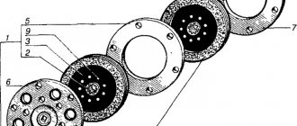
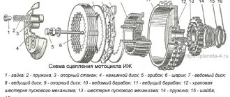
Rice. 4.1. Clutch discs of the motorcycle “Dnerpr-11/16. 1 — disk assembly; 2 - hub; 3, 5, 6, 7 - disks; 4 - spring; 8 - screw; 9 - rivet
Rice. 4.2. Clutch release mechanism: 1 — cotter pin; 2 — washer: 3 — ring; 4 - slider; 5 - bearing, 6 - tip; d 1 - rod, 8 - oil seal; 9 — rod assembly, 10 — lever; 11 - bolt; 12 - nut; 13-axis
The need to check clutch parts arises if the clutch pins and pin holes in the drive discs wear out, the pin fits in the flywheel become loose, the splines in the hub of the driven discs wear out, the fastening of the disc hubs becomes loose, the friction discs wear out and the elasticity of the springs decreases. If the fingers are worn out by more than 1 mm, they need to be replaced. To do this, press out the worn pins, having previously measured the amount of protrusion of the ends relative to the plane of the flywheel. Press in new fingers (Fig. 4.3), leaving an allowance at the ends for grinding. Then the fingers are polished. After grinding, the ends of the fingers should be in the same plane. The runout of the ends relative to the conical seating surface of the flywheel should be no more than 0.2 mm. If the walls of the holes in the drive disks are damaged, then you need to drill new holes with a diameter of 196 mm between the old ones (hole diameter 12.5 - 12.57 mm). Discs with worn out linings and splines in the hub are replaced with new ones. If rivet connections become loose, they must be riveted or replaced. Clutch springs must have the same stiffness. New parts, when compressed to 21 mm and depending on the load, are marked with paint: 17.5 - 19.0 kgf - gray, 16.0 - 17.5 kgf - black. The free springs are about 45 mm long.
Rice. 4.3. Clutch pin
Rice. 4.4. Device for disassembling and assembling the clutch: 1 -bar; 2-bolt
Rice. 4.5. Gearbox: 1 — gearbox fastening nut; 2 — air corrector pipe; 3 - additional hole; 4 - filler neck; 5 — screw securing the clutch disc; 6 — clutch disc
content .. 31 32 33 ..
How to properly monitor the Dnepr gearbox
10/26/2014 NEMEC Add a comment
4705
“Dneprovskaya” (MTovskaya among the people) has proven itself on the positive side and is a success. Even I was looking for just such a gearbox for my Cacique, because I don’t have a rear one and it’s difficult to find neutral. Yes, and it adds a little speed (Dnepr gearbox). For this case, I will publish a post about how to properly maintain the MT gearbox.
Since 1971, the plant has installed the MT804000 gearbox with reverse gear and a forced clutch release mechanism when changing gears on all Dnepr motorcycle models. Maintenance of this box is easy. The main thing is to always check and monitor the oil level using the dipstick. In a working box, it is practically not consumed, but the occurrence of an accidental leak can lead to failure of the unit. So keep a close eye on him. At the factory, the box is filled with M8A GOST 10541-78 engine oil. The first oil change is made after 500 kilometers in order to remove the products of running-in parts along with it. In the future, under normal operating conditions, it is changed after 5 thousand kilometers. If possible, it is better to use transmission oils TAD-17 or TAP-15V, which have twice the service life (10 thousand kilometers). During operation, it is necessary to monitor the adjustment of the forced clutch release mechanism. Failure to adjust is possible due to wear of parts, especially those that operate without protection from dust and dirt.
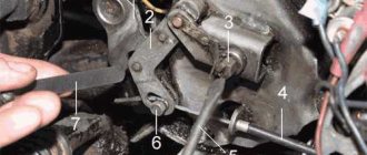
A few words about the operation of this mechanism. When changing gears, the cam-crank 2 (Fig. 1), connected to the shift pedal 1, turning forward or backward from its middle position, raises the long arm of the lever 4 with roller 3. The short arm of this lever acts on the composite intermediate rod 5, which has an outer the end presses on the adjusting bolt 6 of the outer clutch release lever 17. The latter, swinging on the axis 18, acts on the clutch release rod 12 through the slider 16, bearing 15 and tip 13. In the design of the mechanism, the regulating element is bolt 6. It must be screwed in so that there is a small gap between its end and the end of the intermediate rod 5, ensuring free play of the front arm of the shift pedal of no more than 10 mm. The adjusting bolt must not be screwed in too deeply until the free play disappears, since in this case the thrust bearing 15 will be clamped between the slider 16 and the tip 13, and the pressure plate 8 will be pressed away from the flywheel by the clutch release rod. As a result, the bearing and clutch of the Dnepr motorcycle may fail when it slips. It is also impossible to do so that the adjusting bolt is not tightened and the free play of the pedal exceeds 10 mm. This will lead to shocks and jerks when changing gears in cases where the driver does not use the manual clutch release, and in addition, the clarity of shifting will be disrupted.