content .. 31 32 37 ..
MOTORCYCLE GEARBOX “DNEPR”
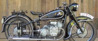
In models MT9, MT10, MT10-36, (“Dnepr-11”, “Dnepr-12”, “Dnepr-16”), MV-750M MV-650, a two-shaft four-speed gearbox with reverse gear and an automatic clutch release mechanism is installed model MT804 (Fig. 4.11).
The box has been equipped with a reverse gear, a mechanism for power release of the clutch when changing gears, and other components have been changed. The gearbox can be installed on motorcycles of the Kyiv Motorcycle Plant models K-750, K-750M, K-650 and on the latest models of Ural motorcycles. If boxes from previous editions are replaced, some modifications will need to be made. The driveshaft needs to be shortened.
For a shaft designed by the Kyiv Motorcycle Plant, this can be done by rearranging the retaining ring, which is located at the rear end of the propeller shaft. If necessary, cut another groove on the shaft, slightly shortening the cardan fork. The fork and shaft can also be connected with a pin (Fig. 4.12). The shaft is shortened on the cardan joint side by such an amount that the end of the shaft is removed from the oiler by a distance of at least 3 mm.
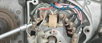
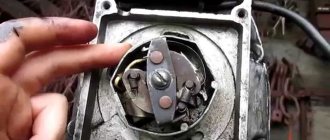
On motorcycles of the Kyiv Motorcycle Plant models K-750, K-750M, the frame is shorter than on subsequent models, so contact between the spring cardan disc and the frame is possible. In this case, bevels are made on the disk and frame (Fig. 4.13). Unlike the box of previous releases, the neutral of the switching mechanism is set by a foot pedal using a lamp-lamp indicator, which is mounted on the instrument panel. The flashlight switching circuit is shown in Fig. 4.14. Unlike the previous gearbox, the housing consists of a crankcase and one cover. A cardboard gasket is installed between the crankcase and the cover, which is lubricated with grease, for example, Litol-24. The gasket does not stick to metal surfaces and remains on the cover or crankcase during disassembly.
Rice. 4.11. Gearbox of motorcycles "Dnepr": 1 - intermediate shaft; 2 - input shaft; 3 - clutch release rod; 4 — dipstick with breather; 5 - crankcase; 6 - idler gear; 7 — idler gear axis; 8 - gasket; 9- cover; 10 — reverse gear shift handle; 11 — clutch release lever; 12 — elastic coupling disk; 13 - secondary shaft; 14 — adjusting bolt; 15 — drain plug; 16 — shaft with the trigger sector; 17 - gear shift pedal
Rice. 4.12. Reducing the dimensions of the driveshaft
Rice. 4.13. Mating the spring clutch disk and the motorcycle frame: 1 - bevel on the disk. 2 - maximum permissible position of the spring clutch disk. 3 — memorial position of the disk: 4 — bevel on the frame
Rice. 4.14. Switching diagram for the neutral indicator lamp: 1 - neutral indicator lamp; 2 - wire, 3 - insulating cap
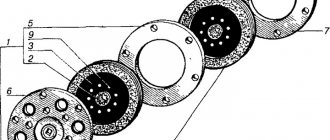
Rice. 4.15. Primary shaft and starting mechanism for motorcycles “Dnepr-11/16”: 1 - shaft assembly; 2 - key, 3 - shaft; 4, 5 — gears; 6 — bearing; 7 - ring; 8 - coupling; 9 — washer; 10 - spring, 11 - washer; 12 - ring; 13 — bushing; 14 - screw; 15 - spring; 16 — washer, 17, 18 — gears; 19 — lever assembly, 20 — lever; 21 - roller; 22 — bushing; 23 - wedge bolt; 24 — washer; 25 — nut, 26 — shaft assembly; 27 - shaft; 28 - sector
Rice. 4.16. Secondary shaft of motorcycles "Dnepr-11/16": 1 - shaft assembly; 5, 9, 11, 15, 20, 22, 23, 29 — gears; 2 - key; 3 - shaft; 4, 8, 10, 14 — bushings; 6, 7, 12, 13 — couplings; 16, 19, 26 — washers; 17, 18 — bearing; 21 - bolt; 24 - nut; 25 — cotter pin; 27 — disk; 28 — disk assembly; 30 - ring; 31 - gasket.
SHAFT OF MOTORCYCLE GEARBOX “DNEPR”
The primary shaft is mounted on two bearings. The shaft is made integral with the rims of the reverse gears, first and second gears. The gears of the third and fourth gears are mounted. The fourth gear gear is kept from turning by a slot key. The third gear gear is connected to the fourth gear gear using end lugs.
The secondary shaft is also mounted on two bearings and has a spline for the reverse sliding gear. Two splined couplings are pressed onto the shaft and are held from turning by keys. The gears of the first, second and third gears rotate freely on cermet bushings, and the fourth gear gear rotates freely on a bronze bushing. The gears are connected to the shaft using movable gear clutches. There is no special supply of lubricant to the rubbing surfaces.
Rice. 4.17. Shafts and gear wheels of the gearbox of Ural motorcycles: 1, 20 - oil squeegee washers; 2, 6, 7, 9 — gear wheels of the 4th, 3rd, 2nd and 1st gears of the driven shaft; 3, 5 — driven shaft and its coupling; 4 — engagement clutch, 8, 27 — clutches; 10 — bolt of the speedometer drive bushing; 11, 12 — bushing and gear wheel of the speedometer drive; 13 — cotter pin; 14, 29 — nuts; 15, 28 — washers, 16 — driveshaft coupling disk assembly; 17 — lever wedge bolt; 18 - lever, 19 - bearing; 21 — block of gear wheels of the 3rd, 2nd and 1st gears of the drive shaft; 22 - key; 23 - drive shaft assembly; 24 — gear wheel of the 4th gear of the drive shaft; 25 — bearing; 26 - gasket; 30, 31 — pawl spring and its pin; 32, 33 — pawl and its axis; 34, 36, 38 - shaft, gear and trigger spring; 35 - pin; 37 — bushing
content .. 31 32 37 ..
MY MOTORCYCLE
The Dnepr motorcycle is one of the most popular “soviet” motorcycles in Ukraine. It is exploited everywhere and everywhere. The engine itself, of course, is as wear-resistant as in the Ural (well, to be honest, our “Kulibins” were a little unfinished), but the gearbox performed quite well. But whatever one may say, when a motorcycle is used for a long time, more or less complex malfunctions arise in the gearbox that must be repaired!
In order for repairs, usually associated with replacing worn parts, to be successful, you need to know, firstly, what caused the malfunction, and secondly, how to properly eliminate it. Otherwise, instead of one problem, you can get another. To begin with, we will characterize the main malfunctions that may occur in the box, their causes and methods of elimination, and then we will deal with the procedure for disassembling and assembling it.
Fig.1. Driven (secondary) and drive (primary) shafts, engine starting mechanism: 1, 20 - ball bearings 304; 2 — washer; 3, 7, 9, 12, 16 — driven shaft gears; 4 - bushing; 5, 10 — gear clutches; 6, 11 — driven shaft couplings; 8 — bushings; 13 — bushing; 14 - driven shaft; 15 — keys; 17 — reverse idler gear; 18 — washer; 19 — gasket; 21 — bolt of the speedometer drive bushing; 22 — thrust bushing for speedometer drive; 23 — driven gear of the speedometer shaft; 24 — speedometer drive gear; 25 — disk of the elastic coupling of the cardan; 26 — washer; 27 — nut;; 28 — cotter pin; 29 — washer; 30 - coupling; 31 - gasket; 32 — ball bearing 205; 33 — gear wheel of the fourth gear of the drive shaft; 34 — gear of the third gear of the drive shaft; 35 - drive shaft; 36 - key; 37 — washers; 38, 39 — intermediate shaft gears; 40 - spring; 41 — bushing mounting screws; 42 — front bushing of the trigger shaft; 43 — rubber sealing ring; 44 - special washer for securing the end of the spring; 45 — gear sector return spring; 46 — gear sector; 47 — trigger shaft; 48 — wedge bolt nut; 49 — washer; 50 - wedge bolt; 51 — rear bushing of the trigger shaft; 52 — lever assembly.
The start pedal goes all the way down, but the crankshaft does not turn. To determine the cause, engage the gear and press the start pedal. If the motorcycle remains motionless, it means that the teeth of gears 38 and 39 (Fig. 1 - see below) of the ratchet mechanism or the starting gear sector 46 are broken and these parts need to be replaced. If the motorcycle moves slightly, the clutch is slipping and its drive needs to be adjusted.
- The start pedal does not return to the up position. If it can be easily lifted by hand, the spring 45 of the trigger mechanism or the special washer 44, the protrusion of which the end of the spring is attached to, is broken. The spring usually breaks off the protrusion that fits into the hole of the gear sector. The washer can wear out and disengage with the cams of the bushing 42. In these cases, it is enough to replace the damaged spring or engage the washer with the cams of the bushing or sector.
- The large free play of the starting shaft lever 52 is, as a rule, a consequence of the play that has appeared in its connection with the shaft 47. It is enough to drive the wedge bolt 50 that tightens these parts harder and tighten the nut 48 to reduce the lever travel.
- One of the gears does not engage. The reason is the breakdown of one of the pins in gear shift disc 11 (Fig. 2). The disk assembly is replaced with a new one.
- Gears switch out spontaneously when the motorcycle is moving. This may be caused by incorrect adjustment of the forced clutch release mechanism, wear of the splines of couplings 5 and 10 (see Fig. 1), including gears, or gear splines. During repairs, unusable parts are replaced.
- Noisy operation of the gearbox is caused by insufficient oil in it, wear of the gear teeth or bearings of the drive or driven shafts. Worn parts should be replaced when the opportunity arises, without waiting for them to break.
To repair, the gearbox must be removed from the motorcycle and disassembled. These works are described in the instructions supplied with the machine by the factory, and usually do not cause any difficulties. Assembly is another matter. It is important here not only to install the parts in a certain order, but the main thing is to ensure the required nature of their connection. If, say, a gear must sit motionless on a shaft in order to rotate with it, then its hole in diameter must be smaller than the shaft. Conversely, a freely rotating gear must fit onto the shaft with a certain clearance. Deviations from these requirements, caused by wear of parts, disrupt the operation of the mechanism. Therefore, after disassembling and washing the parts, it is advisable to check their main dimensions, which must correspond to the values given in the table, otherwise, soon after replacing only the damaged part, the gearbox will have to be disassembled again to install a number of new ones. We recommend assembling the box in the following order, by unit:
Press into the cover 14 (Fig. 3) the ball bearing 17 of the drive shaft until it stops, the idler gear axis 15 is flush with the outer wall of the cover (tightness of at least 0.01 mm), alignment pins 16 and 19 (tension of at least 0.03 mm), rear bushing of the starting shaft (tension less than 0.025 mm) and oil seal 3. Install bracket 25, previously assembled with lever 24 and roller 22, and secure it with nut 5 with flat washer c. Install oil seal 1 into the hole for the driven shaft. Press key 36 into the drive shaft 35 (see Fig. 1) of the gearbox and then press gear 34 of the third gear onto it until it stops. The 0.05 feeler gauge should not pass between the end of the pressed gear without distortion and the shaft shoulder. Place gear 33 of the fourth gear on the shaft and bring its cams into full engagement with the cams of gear 34 of the third gear. Press ball bearing 32 onto the shaft until it touches the end of gear 33, put on gasket 31 and press coupling 30 onto the shaft so that it fits tightly onto the gasket. Place bushing 13 on the front end of the driven shaft 14 until it stops in the splines, onto it - gear 12. Press in two opposite keys 15, put coupling 11 on the shaft, and on it - coupling 10, bushings 8 and gears 9 and 7 on them. Press in the remaining two keys 15, put coupling 6 on the shaft, and on it - engagement coupling 5. Press sleeve 4 onto the shaft until it stops in coupling 6, put gear 3, washer 2 on the sleeve and press ball bearing 1 until it stops. gear 16, washer 18 and spacer 19. The entire set of parts assembled on the driven shaft will be secured when the ball bearing 20 is pressed onto its free end. All gears of the driven shaft should rotate easily on the shaft without jamming (radial clearance 0.02-0 ,1 mm), gear clutches - move freely along the splines of the driven shaft couplings. Once you are convinced of this, you can lightly lubricate all the rubbing pairs with oil, which will be used to fill the gearbox, in order to save the parts from dry friction in the first minutes of operation of the unit on the motorcycle.
Press gearshift disc axis 25 and lever lock axis 22 into crankcase 3 (Fig. 4). Screw the stop 20 of the cam-crank return spring to the crankcase with bolt 17. Screw the rubber buffer 28 of the gear sector of the trigger mechanism with lining 27 to the crankcase with two bolts 30 with washers 29 and nuts 26. The nuts must be secured with a cotter pin. Press in bushing 31 and oil seal 33 with spring 32. Press in intermediate shaft 13 with the short end. Place washer 37 on this shaft (see Fig. 1). gear 38 with the cams outward, then put the gear 39 with the cams on gear 38, the second washer 37 and spring 40.
Press axle 18 into the crankcase (see Fig. 2) and put pawl 19 on it. Install gear shift assembly with pedals into the pressed bushing 31 (see Fig. 4) and oil seal 33. Place the return spring 6 on the inside of the crankcase and place its end behind the protruding tendril of the stop 20 (see Fig. 4). Place cam-crank 7 on the splined section of the shaft (see Fig. 2), placing the second end of the spring behind the cam pin. Place spring 8 and ring 10 onto the second crank pin. Place the end of the crank pin into the shift pawl groove. Place washer 9 on the threaded end of the shift shaft and tighten it all with nut 12, which is secured with cotter pin 13. Install lever 23 (see Fig. 4) in the crankcase for engaging reverse gear. Install shift disk 11 on the axle (see Fig. 2) after first securing the gear shift disk retainer spring 17 to it. install lever lock 16 (see Fig. 2) on axle 22 (see Fig. 4), rest one end of spring 17 against the crankcase wall, and place the other end on the lock. Place washer 15 (see Fig. 2) on axle 22 (see Fig. 4), insert cotter pin 14 into the hole of the axle and separate its ends.
Now you can move on to the general assembly of the gearbox. Press the previously assembled drive and driven shafts into the crankcase. Insert gear shift forks 1 and 2 (see Fig. 2) into the grooves of the couplings switching the driven shaft and into the groove of gear 16 (see Fig. 1) reverse gear fork 3 (see Fig. 2). Insert roller 4 into the holes of the shift forks and install it in the corresponding hole in the crankcase. Insert the pins of gearshift forks 1 and 2 into the grooves of the shift disk, and insert the pin of the reverse gear lever into the groove of the fork 3. Screw the stop 14 (see Fig. 4) of the idler gear to the crankcase with screw 15. Screw in the sensor contact with plug 5. Install the assembled gearbox cover onto the shafts, having previously coated their planes and the gasket with some sealing compound. With light blows of a hammer (not steel), seat the cover until the planes touch and tighten the nine coupling bolts 7 crosswise (see Fig. 3) with washers 8 on them. In the assembled box, the shafts and gears should rotate easily by hand without jamming. Press drive gear 24 (see Fig. 1) of the speedometer drive onto the shank of disk 25 of the elastic coupling. Using light blows of a hammer, press the elastic coupling disk assembly onto the driven shaft so that the hole for the cotter pin is between the fingers of the disk. Place washer 26, tighten nut 27 as far as possible and secure it. Insert the driven gear 23 of the speedometer shaft into the hole in the crankcase, having previously lubricated its lower end with grease, insert the bushing 22 N through the recess on it and screw in bolt 21. To wind the return spring of the starting shaft sector, it is necessary to turn the front bushing 42 180° counterclockwise and secure it two screws. Install lever 52 on the protruding end of the trigger shaft and secure it with wedge bolt 50. Install the clutch release mechanism and screw in drain plug 9 (see Fig. 3) with washer 10 and breather 13 assembled with dipstick 12.
After installing the gearbox on your motorcycle, do not forget to fill it with oil.
That's the whole robot. If you understand it well, it’s not difficult at all - the main thing is to be careful!
Messages [1 to 20 of 40]
1↑ Topic from olegich 10-12-2012 22:57:12
Topic: please help me how to properly remove the box from the Urals without removing it from the motorcycle
Explain to a beginner how to remove the gearbox from the Urals without removing the engine from the motorcycle
Edited by olegich (10-12-2012 22:57:48)
2↑ Reply from mexanik62 11-12-2012 10:32:54
Re: please help me how to properly remove the box from the Urals without removing it from the motorcycle
Place it on the center stand Remove the rear wheel Remove the final drive Remove the fork Remove the elastic coupling Remove the clutch lever and whatever else you can remove from the clutch Remove the box just don’t forget about the clutch rod
3↑ Reply from olegich 11-12-2012 14:17:31
Re: please help me how to properly remove the box from the Urals without removing it from the motorcycle
Place it on the center stand Remove the rear wheel Remove the final drive Remove the fork Remove the elastic coupling Remove the clutch lever and whatever else you can remove from the clutch Remove the box just don’t forget about the clutch rod
how to remove main gear
Added: 11-12-2012 10:17:31
and you can remove the box without removing the main gear
4↑ Reply from mexanik62 11-12-2012 15:02:59
Re: please help me how to properly remove the box from the Urals without removing it from the motorcycle
Unscrew 2 or 4 nuts (depending on who) securing it to the fork leg
you can remove the box without removing the main gear
It is necessary to remove the engine mounts and move it forward (remove the silencers naturally)
5↑ Reply from [Leshy] 11-12-2012 15:58:14
Re: please help me how to properly remove the box from the Urals without removing it from the motorcycle
Unscrew 2 or 4 nuts (depending on who) securing it to the fork leg
you can remove the box without removing the main gear
It is necessary to remove the engine mounts and move it forward (remove the silencers naturally)
Why unscrew the divglo? I’m on the Dnieper 10, in my opinion, I removed the box without unscrewing the engine, you just unscrew the box, and then you’ll figure it out) and also, to pull it out, the platform on the battery is bent a little, and there will be a small problem with the clutch) but not It’s difficult, I took it off in about 30 minutes) you’ll figure it out
6↑ Reply from VlAiSLAV 11-12-2012 19:20:29
Re: please help me how to properly remove the box from the Urals without removing it from the motorcycle
Unscrew 2 or 4 nuts (depending on who) securing it to the fork leg
you can remove the box without removing the main gear
It is necessary to remove the engine mounts and move it forward (remove the silencers naturally)
Why unscrew the divglo? I’m on the Dnieper 10, in my opinion, I removed the box without unscrewing the engine, you just unscrew the box, and then you’ll figure it out) and also, to pull it out, the platform on the battery is bent a little, and there will be a small problem with the clutch) but not It’s difficult, I took it off in about 30 minutes) you’ll figure it out
on the Dnieper it is on the Dnieper. here the Ural won’t roll with it, there’s a little less space there, so you have to push the engine forward a little
7↑ Reply from Shaman 11-12-2012 19:22:50
Re: please help me how to properly remove the box from the Urals without removing it from the motorcycle
in the Urals it can also be removed without unscrewing the engine
8↑ Reply from partizan 11-12-2012 19:50:37
Re: please help me how to properly remove the box from the Urals without removing it from the motorcycle
Olegych, the main gear means the gearbox (the one that turns the rear wheel). in the Ural, everything can be removed just as easily: you take off the wheel (rear); unscrew the brake rod from the lever on the gearbox; unscrew that same gearbox (main gear); disconnect the speedometer cable from the box; take off the clutch cable; unscrew three nuts and one bolt (fastening box to the block); you move the box back, while kicking it slightly to the bottom - it jumps out! The most you can resort to is a large screwdriver or a mounting tool so you don't have to pull it with your hands. GOOD LUCK!
9↑ Reply from olegich 11-12-2012 22:28:06
Re: please help me how to properly remove the box from the Urals without removing it from the motorcycle
I'll do it in the spring, but right now I'm doing the general
Added: 11-12-2012 18:28:06
And after I take it all off and then put it back, nothing will need to be adjusted?
10↑ Reply from mexanik62 11-12-2012 22:30:12
Re: please help me how to properly remove the box from the Urals without removing it from the motorcycle
Clutch and brake
11↑ Reply from olegich 12-12-2012 07:06:26
Re: please help me how to properly remove the box from the Urals without removing it from the motorcycle
How to adjust the clutch and how to adjust the brake
12↑ Reply from [Leshy] 12-12-2012 09:11:48
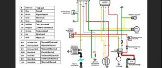
Electrical diagram of the car DNEPR - MOTORCYCLE
Electrical circuits of Dnepr motorcycles of various modifications - Dnepr MT-10, Dnepr 11, Dnepr 16 other models. To enlarge the diagram, click on it.Electrical circuit of the motorcycle Dnepr MT-10
Electrical circuit of the motorcycle Dnepr MT-10 36
1 — left turn signal light Dnepr MT-10, 2 — lamp A12-21; 3 - headlight; 4 — lamp A12-4 for side and parking lights; 5 — lamp A12-45-40 high and low beam; 6 — right turn signal lamp (not connected on a motorcycle with a sidecar): 7 — speedometer; 8 — lamp A12-1 speedometer lighting; 9 — indicator lamp for direction indicators; 10 — warning lamp for emergency oil pressure; 11 — high beam warning lamp; 12 — generator warning lamp; 13 — neutral sensor warning lamp; 14 — instrument panel; 15 - central switch; 16 — direction indicator switch; 17 — turn signal switch; 18 — contact plug; 19 — emergency oil pressure sensor; 20 - light switch; 21 — front light of the stroller 22 — lamp A12-21 for side light and brake signal on the stroller; 23 — fuse block; 24 - generator; 25 - signal; 26 — relay-regulator: 27 — brake signal switch, 28 — Dnepr MT-10 switch; 29 — battery; 30 - breaker; 31 — ignition coil; 32 - high voltage wire; 33 - spark plug tip; 34 — spark plug; 35 — rear light of the stroller; 36 — headlight of the Dnepr MT-10 motorcycle; 37 - lamp A12 15 brake signal; 38 - lamp A12-3 for the side light of the license plate lighting.
Electrical circuit of the motorcycle KMZ-8.155 Dnepr-11 and KMZ-8.922 Dnepr-16
Electrical circuit of the Dnepr-14 motorcycle
1 – emergency ignition switch 2 – day-night switch 3 – connector blocks Dnepr 14 4 – right turn indicators with lamp A12-21 (on a single motorcycle) 5 – handbrake brake light switch 13.3720 6 – speedometer scale backlight lamp A12-1 7 – indicator lamp for direction indicators А12-1 8 – indicator lamp for emergency oil pressure А12-1 9 – indicator lamp for high beam 10 – headlight lamp А12 –45+40 11 – side light lamp in the headlight А12-4 12 – ignition switch 141.3704 13 – left direction indicators with lamps A12-21 14 – relay-interrupter of direction indicators RS 427 15 – direction indicator switch 16 – light switch Dnepr 14 17 – right direction indicators with lamps A12-21 (on a sidecar) 18 – lamp A12-8 of the front side light (on the sidecar) 19 – emergency oil pressure sensor 20 – fuse block 21 – relay-regulator 33.3702 22 – indicator lamp for generator operation A21-1 23 – indicator lamp for neutral in the gearbox A21-1 24 – sensor for switching on the neutral warning lamp 25 – sound signal S-205 26 – ignition coil B-204 27 – breaker PM-302A 28 – horn button 29 – double-filament lamp A12-2+6 for high beam and brake light (on a wheelchair) 30 – foot brake brake light switch 31 – brake light lamp A12-21 32 – tail light lamp A12-5 33 – maesa switch 34 – battery 6MTS-9 or 2KhZMT-6 35 – socket (only on Dnepr -16") 36 – generator G-424 and rectifier 37 – relay RR-330.
CAR ELECTRONICS REPAIR
Dnepr motorcycle gearbox repair
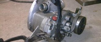
Whether your transmission needs repair or not, you will be able to understand when driving your motorcycle. If there is a strong gear noise coming from the unit, the gears switch off automatically or do not engage (non-engagement), or some gear is jammed, jerks or shocks occur in the transmission - this means that repair cannot be avoided. I advise you not to lay out your road tool on the asphalt, but rather to somehow get to your garage, where there is a more reliable tool and a clean table, because there is nowhere to rush.
The first step is to remove your transmission from the motorcycle. To do this, remove the rear wheel, rear axle with driveshaft, disconnect the neutral wire and disconnect the clutch cable. Don't forget to remove the air filter. Before disconnecting the box from the engine and removing it from the motorcycle, I advise you to drain the oil from it by unscrewing the drain plug at the bottom. And before moving your gearbox onto a clean table or workbench, thoroughly wash it from any dirt on the outside. There are plenty of cleaning chemicals on the market now that can make the crankcase of any unit look like new, but Solvent can also be used. A clean gearbox will be much easier and more enjoyable to disassemble.