Hello.
Continuing the topic: no spark on dio 34.
We figured out the ignition switch using a multimeter. And now let’s move on to less common malfunctions and breakdowns in the electrical wiring of any 2t scooter from a Japanese or Chinese manufacturer. Be it a Honda Dio 34, 18, 27, 35, tact or older tacty, Suzuki, Yamaha. Of course, you are familiar with the situation: the scooter will not start. The spark is gone. What to do?
Let's figure it out.
What is a switch and why is it needed?
To put it simply, a switch is a certain module (according to Feng Shui - a DC CDI or AC CDI module) in which electrical energy is accumulated, which at the right moment is supplied in the form of a pulse to the ignition coil, where it is multiplied many times and jumps out in the form of an electric spark between the spark plug electrodes.
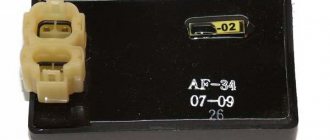
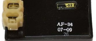
The scooter switch looks something like this
Depending on the type of commutator, the energy necessary for the formation of spawn can be accumulated in the commutator in two ways:
- On switches of the AC CDI type - the energy required to form a spark on the spark plug is first formed in the high-voltage coil of the generator and then, in the form of alternating current, enters the switch, where it accumulates in the capacitor and at the right moment is supplied to the ignition coil in the form of a pulse
- On DC CDI type switches, the energy required to form a spark on the spark plug in the form of direct current comes directly from the battery, where it is converted into alternating current, multiplied by voltage and supplied to the capacitor
Offal
The switch power coils on the generator look something like this. Some generator models have two, some have only one.
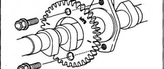
To allow the spark to pass through at the right moment, a magnetic induction sensor (in collective farm parlance - “Hall sensor”) is included in the design of the generator and the switch like it. A magnetic induction sensor is essentially a regular alternating current generator, only in miniature.
On the outside of the generator rotor there is a small protrusion, when passing near the sensor - a small alternating pulse is formed in the sensor windings, which is sent to the switch thyristor - the thyristor opens and the energy accumulated in the capacitor is supplied to the ignition coil
Sensor
Sports switch Honda dio af34/35
✔ in stock
RUB 1,780
about the product
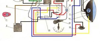
DO NOT connect without battery!!! Check that the battery terminals are securely connected! Also suitable for Bajaj Boxer (connect according to the diagram) Due to automatic adjustment of the ignition timing, it increases power throughout the entire speed range. The digital circuit allows you to very accurately select the SPD and the accuracy does not decrease with increasing revolutions; this switch can operate up to 12 thousand revolutions. The dependence of the SOP on the speed in this switch is selected for maximum power/speed. Does not fit Chinese 4-stroke scooters! Before connecting, make sure that the voltage in the on-board network is no more than 15 volts (the norm is 14.5 V with a working regulator)! This is especially necessary if the old switch burns out. Otherwise, the new switch may also burn out. The measurement can be carried out with a multimeter on the terminals of the connected battery. If the test is done on a new switch and you don’t know whether the voltage in the network is normal, but the old switch is out of order, then the new switch, for safety and testing, MUST BE POWERED FROM A SEPARATE BATTERY. And then check the voltage in the network with the engine running. Pinout (connecting the switch): Be sure to check the location of the contacts before connecting; if the colors of the wires do not match the photo below, rearrange the contacts in the block.
The switch is suitable for all Honda dio with engines af34, af35, af51 including cesta, regardless of the shape of the connector, the main thing is to connect it correctly according to the diagram above. This switch can be used to solve the problem of a burnt zener diode in Honda ignition switches such as af34, af35, af51, lead 100, etc. The essence of the solution: Often, when installing an alarm on scooters with an ignition switch with a zener diode, in particular, when the autostart is turned on, the zener diode (sometimes called a diode) burns out. The function of the zener diode in the ignition switch is to reduce the standard voltage of the 12 volt network to 10-8 volts, this reduced voltage is supplied to the switch “letting you know” that the ignition switch is in order, this is a kind of protection against theft, so that it is impossible to start the engine simply by shorting the wires, of course if the zener diode is burned out, the switch “does not see” the ignition switch and does not produce a spark. In our switch, this function has been removed, so the pink wire from the ignition switch is not connected anywhere and the zener diode in the ignition switch is no longer needed, no matter whether it is intact or burnt out. When connecting to scooters with a connector different from ours, you will need to rearrange the wires according to the connection diagram. You can purchase an external connector for such a switch separately, link:: /razem-dlya-kommutatora-139qmb-152qmi-157qmj.html
Testing the switch
In order not to waste time, the test should begin by checking the electrical impulse that accumulates in the switch and at the right moment goes to the ignition coil.
We take a control light and connect one end of it to the green ground wire, the other to the black and yellow wire of the ignition coil. We turn the engine with the starter.
- If the light does not light, check the modules that ensure the operation of the switch
- If the light comes on, the switch and the modules that ensure its operation are working properly and the reason for the lack of a spark should be sought not in the switch, but, for example, in the ignition coil, ground or wires supplying current to it
If the switch and the modules that ensure its operation are in good working order, a 3W light bulb should glow at half-glow when the engine is cranked by the starter.
Checking the ignition coil
Disconnect the battery and remove the beak on the scooter. We disconnect the connector on the switch and measure the resistance on the coil with a meter. We put one probe in the connector on the black wire, and the second on the negative (green wire). There should be 4 ohms - this means that the wiring and the primary winding of the coil are working properly.
Next step.
We check the second winding of the coil. We take out the probe from the contact of the green wire and insert it into the candlestick instead of the candle. And we leave the other probe on the contact of the h/w wire. The resistance should be about 7.85 kOhm. This indicates that the second winding, the armored wire and the candlestick itself are in good working order.
Let me remind you that the armor wire and the candlestick separately from the coil have a resistance of 5 - 8 kOhm. Such resistance is needed to suppress radio interference from the spark discharge, so as not to interfere with others listening to the radio in the car or at home. If you make an armored wire and a candlestick without resistance and drive next to someone who is listening to the radio. Then the radio stops working normally and begins to crackle in time with the spark discharge on the scooter (moped).
And if the device shows a break (i.e. does not react at all), then remove and check the candlestick and armored wire separately. If they ring, it means a break has occurred in the ignition coil. It cannot be repaired, it is solid, you will have to replace it with a new one. It's inexpensive and you can always buy it without any problems.
Weight check
If there is any suspicion of a malfunction of any scooter ignition module, the ground is first checked. Although, mass in two-wire wiring is a relative concept, but for now let’s call it that.
We take the tester, switch it to the “continuity” mode (diode icon or sound signal icon), look for green wires on the switch - this is something other than ground (in Feng Shui - negative wire), touch the metal part of the engine with any probe of the tester, with another poke the probe into the green wires:
- If there is mass, the tester will beep
- If the mass is bad, numbers will appear on the tester display
- If there is no mass, the tester will be silent, and the screen will show only zeros
Depending on what the tester shows you, fix the problem or continue testing:
- If the ground is bad, look for a break or oxidation in the wiring
- If there is no ground, look for an open circuit or connect it directly from the engine
- If there is mass, but there is no spark, we continue checking
An example of a good mass: the tester beeps in the “dialing” mode, the display shows solid zeros
Power check
In order for a spark to jump between the spark plug electrodes, the commutator capacitor must be charged from something. And it is charged either from a battery or from a generator. Means what? Right! We check whether power is supplied to the switch.
Before you start measuring power, let’s determine what type of switch is on your scooter. Visually, switches of the DC CDI type are twice as large as AC CDI. But this is not an exact criterion. The most accurate criterion is to look at the output of the high-voltage coil of the generator:
- If it is not activated, it means that your scooter is equipped with a DC CDI type switch
- If enabled, then vice versa - your scooter is equipped with an AC CDI type switch
The output of the high-voltage coil of the generator is located in the same place as the output of the generator itself: we are looking for where the wires coming from the generator are connected to the on-board network of the scooter and if one of the two wires with round terminals is not connected, then the coil is not activated
Checking the power supply of a DC CDI switch
If you have the wire of the high-voltage coil of the generator hanging idle (provided that everything was like this from the factory, and not after the intervention of some “guru”) - switch the tester to the DC measurement mode in the 20 V range. Look for the wire on the switch nutrition. Usually this is a black or gray wire; we touch the ground with one probe and the power wire with the other:
- If the display shows zeros, look for an open circuit in the power wiring.
- If the voltage is significantly less than 12v, look for oxidation or check if your battery is charged
- If the voltage is 12v or a little more, then everything is in order with the power supply and you can check further
The power supply to this switch is in perfect order.
Checking the Pulse Generator
We measure the resistance of the Hall sensor coil at the switch connector. We set the device to 2 kOhm. We connect one probe to the green wire, and the second to the s/w. Should be 114 ohms. This means the wiring and Hall sensor are working properly.
If the circuit does not show resistance, then this indicates a break in the coil or electrical wiring from the pulse generator to the switch.
Next, we check the functionality of the entire pulse generator along with the mechanical part. Switch the device to 2 mA, leaving the probes in place.
We pull the leg of the kickstar. From the Hall sensor, for one rotation of the magneto, one pulse with a small current is supplied to the commutator. The meter should show approximately 0.6 mA. This means that all elements of the pulse generator are working properly and the reason for the lack of spark is not in the Hall sensor.
If the device does not show current, then you need to remove the air cooling casing. Look at the gap in the mechanical part of the generator, between the magneto and the Hall sensor. Check to see if the crankshaft bearings are loose or if the wire from the sensor is broken.
Checking the power supply of the AC CDI switch
We switch the tester to the alternating current measurement mode for the 200V range. We touch the ground with one probe, the power wire with the second and crank the engine with the starter:
- If the supply voltage is at least 60-65V, the power supply is normal.
- If the voltage is significantly less or absent, check the generator. The supply winding of the generator in the mode of cranking the engine with the starter should produce at least 60V, and at average engine speeds - about 160V
Checking the generator sensor
The magnetic induction sensor is a key element of the ignition system. And if there is any suspicion of a problem with the ignition system, it should also be checked.
Switch the tester to AC measurement mode in the 2V range. With one probe we touch the ground, with the second probe we touch the white-blue or red-yellow wire coming from the sensor and turn the engine with the starter.
- If numbers flash on the screen, there is an impulse
- If the display shows zeros, check the sensor
There is momentum
Let's summarize the above
First, use a light bulb to check whether the switch generates a pulse or not:
- If the light is on, the switch and the modules that ensure its operation are 100% operational
- If the light does not light, it means that the switch or some module that ensures its operation has failed. And to understand for sure that the switch is faulty, we need to check all the modules.
- If the modules turn out to be serviceable, but the switch does not generate a pulse, then it is faulty and you can safely replace it with a new one
In conclusion, I would like to warn you against the temptation to take a known-good switch from someone and plug it in instead of your own. Yes, with this express method the faulty switch will be identified immediately. If it was really faulty, then with a known good one, a spark will immediately appear.
But how can we be 100% sure that the wiring of the scooter is in perfect order and no one has managed to put their smart personality into it before you?.. What if something shorted or some tusk messed up the wiring in his own way and then the working switch will receive a “complete butt”. And then you will buy two switches - one for the person you asked for, the second for yourself. Do you need it?
Removing the rev limiter in the Honda Dio AF 34/35 switch
ATTENTION! The speed limiter can be removed only for switches marked: CI649 and CI649A. For switches with other markings, it will not be possible to remove the limiter, and if you try, you will simply ruin the switch, and your scooter won’t even start...
If you don’t know how to solder, then contact a friend who knows how to do it and show him this article, and If you don’t know such a friend, then contact any electronics specialist or auto/motorcycle specialist and also show him the article, he will do everything for you.
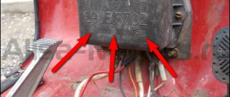
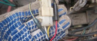
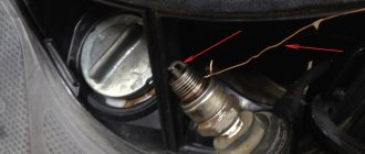
How to remove the switch and where is it located?
The switch is located at the front of the scooter under the beak (the largest part of the plastic is at the front). The beak is attached to 3 large bolts in front, and 4 under the dashboard (two on each side), unscrew 3 large and 4 small bolts. Now you can remove the beak! Removed? Now we are looking for a metal platform: You just need to pull the switch up (you can help with a flat screwdriver) so that the switch is removed from the metal fasteners (marked in the photo). Filmed? Now, as you can see, the wires are connected to the switch, disconnect them (then it will be impossible to connect them back incorrectly, so don’t worry :)). There is a rubber band on the switch, remove it! That's it, the switch is ready for resoldering.
The limiter in such switches is a capacitor (such a yellow plastic piece), which will need to be soldered to another (the price is no more than 3 rubles), the approximate location of the limiter is in the diagram. Next, let's get to work...
Turn on the soldering iron and take a craft knife (you can use a simple one, but make sure it’s well sharpened). We take the switch and begin. To make it easier to pick out the sealant, you can remove the side plastic walls (at the edges of the place that is marked, do not throw away these plastic walls!!!), it is better to do this right away, because when resoldering the capacitor you will still need to remove the walls, These walls are plastic and can be removed using a soldering iron (what the switch will look like after removing the walls is in the photo below). You need to pick the sealant very carefully, remove it millimeter by millimeter, otherwise you can damage the parts. After 20-40 minutes of work, you should see a yellow plastic piece (this is the limiter), you should not pick the sealant more than the marked area, this is not necessary and you can hit other parts. Next, we pick out about 2-3 mm of sealant around this yellow plastic piece (capacitor) so that it can be desoldered. Now we take a soldering iron in our hands (it is better to clean the soldering iron tip with a file to make it easier to desolder the capacitor) and begin to carefully desolder the capacitor if you break it no problem, the main thing is to remove everything that is left of the capacitor from the switch. There should be a ready place for soldering a new one. So half the work is done, now you need a new capacitor, you can buy it in a radio parts store (costs no more than 3 rubles), it should be 50 V (Volts) 4.7 μF (microfarads), in the store just say: “Give me a 50 Volt 4.7 microfarad capacitor.” Also ask the seller where is + and where is - on the capacitor and remember (usually the short leg of the capacitor is a minus, but it’s better to let the seller explain to you). It's time to solder a new capacitor, shorten the legs of the capacitor by about 2/3 (more than half), and do not forget where the plus is and where the minus is. How to properly solder a capacitor is shown in the photo: Has everything been soldered? Give the switch a good crack, but the soldered capacitor should not fall out! And if it falls out, then solder it again, but better!!! That's it? Then we carry it in this form to connect it back to your scooter, BUT do not secure the switch yet (do not put an elastic band on it or place it on a metal platform), this is still just a test! Is everything connected? Press the brake and the START button (or start the scooter from the foot if the battery is dead). Didn't start? This means that you carelessly disassembled the switch and damaged other parts (to find out which parts you damaged, contact a good specialist, let him find out which parts you damaged and replace them himself, or, if you have enough experience, replace them yourself). Started up? Hooray!!! You did everything right! Now let's check. We sit on the scooter while we temporarily secure the switch (with tape or tape, or in some other way), drive out onto a straight, flat road and check the speed! If your scooter does not run for more than 40, it means that you soldered the capacitor poorly or they sold you a defective one... Just re-solder it again or replace the capacitor with a working one. And if the needle moves smoothly to 60 and beyond (in any case, the speed should increase by 5-20 km/h depending on the condition of the cylinder-piston group, transmission and other technical components of your scooter), then everything is ready, you did everything right! Congratulate yourself and go to the garage: there are very few things left to do! We remove the temporary fastening, now again with a soldering iron (or with super glue) we melt (or glue) the plastic walls so that they hold well and do not fall off from any pressure on them (see photo below). Did you attach it? We take a sealant (absolutely any sealant will do, you can buy it at a car store (about 30-200 rubles)) and fill it with the entire part that you previously picked apart (if it is not possible to buy a sealant, then for the first time you can put some soft rubber to the uncovered place and wrap the switch with electrical tape). We wait until the sealant dries (about a day (if there are no manufacturer’s recommendations), but it is better to read what time the manufacturer recommends, it can be much less).
Is the sealant dry? Then that’s it, put an elastic band on the switch and put the switch and plastic in place, screw everything on.
Now get on the scooter, start it up and get all the maximum revs and all the top speed that your scooter can do! Good luck!!!