The Czechoslovak motorcycle has a number of advantages compared to other Soviet units, but is almost the same in terms of electrical equipment. The JAVA 638 wiring diagram is quite simple. Even an inexperienced motorist can handle repairs and maintenance.
Adjusting the ignition of the JAVA 638 is very important for the correct operation of the engine. You can do it yourself at home. To do this you need:
- Remove the spark plugs from both cylinders and remove the sump cover.
- After removing the spark plugs, install the indicator in the hole of the right cylinder.
- Now you need to fix the piston at top dead center. To do this, turn the crankshaft using a key.
- Then the cylinder contact spacing is adjusted. They should only touch slightly (distance approximately 0.35 millimeters ).
- A light bulb is connected to the contact on which the advance is set. This is done before setting up the ignition on the JAVE 638, to accurately measure the distances between the contacts.
- Zero is measured on the indicator, after which the position is fixed.
- The advance is different for each gasoline. So, when using the 92nd and 95th, the adjustment is 2.7-3.1 millimeters, for the 80th – 2.9-3.3 millimeters.
- If the installation is correct, the light goes out. Otherwise, adjustment will be carried out by a movable disk.
- An identical procedure is carried out on the other cylinder.
- When the adjustment is completed, crank the crankshaft several times using the kickstarter. Then the control ignition advance is performed. This completes the YAVA 638 ignition installation.
It is important to understand that if the ignition is incorrectly measured, the engine's operating life will be reduced.
Adjusting the ignition timing of Jawa 350
31 Aug 2012
Motorcycle engines have constant or variable ignition timing. With constant ignition timing, the beginning of the breaker break, and, consequently, the appearance of a spark, remains unchanged in all engine operating modes. With variable ignition timing, the moment of spark appearance is changed manually or automatically - with a centrifugal regulator, which, as the speed increases, increases the ignition timing from 10 to 30°. (see continuation)
In domestically produced motorcycles, the ignition timing is set according to factory data:
For two-cylinder engines M-61 and K-750, the breaker cam is a continuation of the camshaft, so the ignition timing is set at the factory. These machines have the same hammer break value for the right and left cylinders.
To control and adjust the ignition timing on motorcycles with classic (cam) ignition, it is convenient to use an ICH dial indicator. Its main scale is graduated both clockwise and counterclockwise, and this is very convenient when setting and checking the ignition (the black numbers count when the arrow rotates clockwise. In this case, the upper rod of the indicator extends. The red numbers, on the contrary, the arrow rotates counterclockwise and the upper rod slides into the indicator body). The scale division is 0.05 mm. The auxiliary scale located slightly to the right of center (the one that is smaller) has a division value of 1 mm. To secure this indicator in the spark plug hole of the cylinder head, you need to turn an adapter on a lathe or make it yourself from an old spark plug.
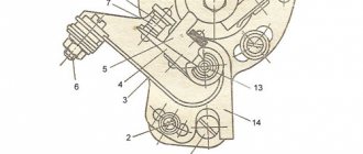
- - hole for decompressor;
- - rod for determining c. m.t.;
- — fixed contact of the breaker;
- — breaker lever;
- - fist.
Remove the right engine crankcase cover. Remove the spark plug and replace it with a device for determining the position of the piston. Turning the crankshaft with a wrench S=10 mm, placed on the head of the cam mounting bolt, place the piston in the idle position.
Set a gap between the contacts equal to 0.3 - 0.4 mm, to do this, loosen the screw securing the anvil and turn it around its axis in the desired direction. After tightening the screw, check the gap - a feeler gauge with a thickness of 0.3 mm should pass easily, but a feeler gauge with a thickness of 0.4 mm should not pass through.
Connect the test lamp with one wire to the terminal clamp of the hammer, and the other to any ground point of the motorcycle. Turn on the ignition, and the lamp connected in parallel to the breaker contacts should light up.
By turning the crankshaft counterclockwise, lower the piston by the amount of ignition timing specified in the instructions. Count down according to the device. At the moment when the piston takes the desired position, the lamp should go out, signaling the closure of the contacts. If the contacts close earlier (the lamp goes out), it means the ignition is later, and later the ignition is early. In both cases, slightly loosen the screws securing the breaker disk and lightly hit the bent stop 12 (using a screwdriver) and turn it clockwise if the ignition is early, and counterclockwise if it is late. Tighten the base mounting screws and check the ignition installation. To do this, lower the piston 5 - 7 mm (the lamp does not light - the contacts are closed) and slowly raise it again. The lamp should light up (the contacts will open) at the moment when the piston does not reach TDC. by the amount of ignition timing (see TABLE ABOVE). Turn the crankshaft several times using the kick starter, and then check the ignition timing again when the piston moves to the top dead center. It should be remembered that when performing this work, you cannot keep the ignition on for a long time, so as not to damage the ignition coil.
On the Java-350 motorcycle, the ignition timing is adjusted in a similar way, first for the right cylinder - accordingly, the upper breaker, then for the left - the lower breaker. To do this, loosen the fastenings of the base (disk), and then for the left cylinder - the fastenings of the sector. To ensure synchronous engine operation, the ignition timing in both cylinders should be set to the same.
It sometimes happens that the required ignition timing of the JAVA 350 cannot be set due to the insufficient length of the groove limiting the rotation of the base. This indicates excessive wear on the breaker hammer stop or chipping. In this case, you need to replace the stop or install a new hammer.
During operation, the heel of the breaker hammer wears out and its height decreases. The anvil and hammer with contacts less than 0.5 mm thick are replaced with new ones. The wear occurs especially intensively after installing a new hammer. Changing the height of the heel of the hammer causes a change in the ignition timing.
Wear reduces the gap between the breaker contacts and the initial advance value, and installing a new unused hammer to replace the failed one increases the gap between the breaker contacts and the ignition timing. Therefore, after replacing the breaker parts, it is necessary to adjust the ignition timing.
extreme.newline.by
FUOZ Saruman
Control and adjustment of ignition timing of Java 634 and Java 638 motorcycles.
Rice.
1. Breaker Java 638 Monitoring and adjusting the ignition timing on the Java 350/638 motorcycle can be considered one of the main adjustment operations. Let us only recall that advance refers to a certain moment before the end of the compression stroke, at which the fuel mixture in the combustion chamber of the cylinder is ignited. Adjusting the ignition timing consists of two main operations, namely: setting the specified separation of both choppers located on the top of the generator, and adjusting the fuel ignition timing.
For this purpose, as a rule, gap checking probes are used, which are included in the standard equipment of the motorcycle, and a special measuring device from the service tool kit, which is alternately screwed into the holes for the spark plugs of the right and left cylinders. This measuring device is a cylindrical body (with a M14x1.25 thread at one end), through which a rod passes with marks along the circumference at a distance of 1 mm from each other. For more accurate measurements, you can also use a micrometer with a threaded end.
If you're tired of constantly adjusting your ignition, upgrade to Saruman's state-of-the-art electronic ignition system. It is easy to set up, produces a strong spark and ensures fast acceleration of your motorcycle. Go to FUZ Saruman
Procedure for monitoring and adjusting Java 634 and Java 638 motorcycles.
After removing the right engine crankcase cover, first check that the alternator stator mounting bolts and the cam center screw are properly tightened. If necessary, tighten them with a screwdriver and a 10mm spanner. Check the condition of the breaker contacts, and if necessary, trim their supporting surfaces with a file or sandpaper. If they are worn or burned, replace the rocker arms and contacts. The contacts in the closed state must be adjacent to each other with their entire surface. Unscrew the spark plugs and screw a special millimeter measuring device into the hole under the right spark plug. Do not extend the measuring device, but leave approximately 1 mm from the supporting surface, so that during subsequent measurements you can accurately determine the starting position. First, the ignition advance of the right cylinder is set by the upper chopper, and only then the ignition advance of the left cylinder is set by the lower chopper.
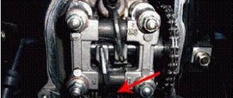
First you need to check and, if necessary, set the correct separation. The separation refers to the maximum distance between the fixed contact of the breaker and the contact of the breaker lever when the lever is raised as much as possible by the cam on the generator rotor. Place a flat or socket wrench of 10 on the central screw of the cam (see figure) and turn clockwise. The position in which the breaker lever is maximally raised by the cam must be noted on a millimeter measuring device. Its rod is in the highest position, which means that the piston of the right cylinder is at top dead center. The distance now between both contacts of the breaker represents its separation, which should be 0.3 mm. This size is checked with gap gauges. The motorcycle accessory kit contains a double dipstick consisting of two plates: 0.3 mm and 0.4 mm. The thin plate (0.3 mm) of the probe should pass between the breaker contacts, but the thicker plate should not pass. If the distance does not correspond to the specified value, use a screwdriver to loosen the fixing screw of the fixed contact holder. Then move the contact holder either towards or away from the breaker lever so as to adjust the separation to the desired value of 0.3 mm. Slightly tighten the screw of the breaker contact holder, and measure the adjusted separation size again with feeler gauges. If everything is in order, tighten the screw completely.
Rice. 2.Java 638 Interrupter
If the breaker lift is correctly adjusted, the ignition timing should be checked and, if necessary, adjusted. To do this, you need to check whether the piston of the right cylinder is still at top dead center. Then turn the cylindrical body of the measuring device so that the mark of the movable rod coincides with the control edge of the body. By turning the crank mechanism counterclockwise, reduce the piston position by the specified ignition timing value of 2.7 ± 0.2 mm before top dead center. The beginning of the separation should be in this position. This is the moment when the breaker contacts begin to move away from each other and there is a gap of about 0.05 mm between them. As you know, the fuel mixture in the cylinder is ignited just at the moment when the breaker contacts are disconnected. To determine the moment of separation, a strip of thin foil or cigarette paper is used, which is inserted between the contacts of the breaker. While turning the crank mechanism, as stated above, slightly move the foil between the contacts until you feel it being compressed by the contacts in the desired position. However, it should be noted that the correct torque may be distorted depending on how much force is applied to the strip of foil or paper, and therefore when it is considered compressed.
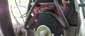
The angular rotation of the crank mechanism and thus the displacement of the piston can be quite large and thus the measurement can be distorted. Therefore, we recommend that to determine the exact moment of disconnecting or connecting the contacts of the breaker, use a regular 12 V electric light bulb (preferably 3 W), in a socket to which two wires with clamps at the ends are attached. One clamp is connected to the terminal of the breaker, the adjustable cylinder, and the other to ground (see figure).
If, with such a connection, the breaker contacts are open and if at the same time the key in the ignition switch is in the “ignition on” position, then the primary ignition circuit is open and the control lamp is on, because current can only flow through the newly connected circuit. The lamp goes out only at the moment we are looking for, when the breaker contacts are connected. If the lamp goes out or if the foil (or paper) is completely compressed between the contacts until the piston position decreases by 2.7 + 0.2 mm from top dead center, then the ignition timing should be increased. Conversely, it should be reduced if, after a given decrease in the piston position, the lamp continues to burn or the control foil passes freely. The ignition timing should be adjusted by turning the base plate of the breakers, slightly loosening the two mounting screws. When the plate is turned to the left, the advance increases and, conversely, when turning in the direction of rotation of the crank mechanism, the advance decreases. Having adjusted the distance between the contacts of the breaker, which corresponds to the moment the separation begins, use a screwdriver to tighten both fastening screws of the foundation slab. Then check the ignition timing again and correct it if necessary. The order of the cylinders mentioned above when adjusting the ignition timing should be observed due to the fact that as a result of installing the foundation plate, the ignition timing of the right cylinder is adjusted, and then on it, as a basis, the breaker plate of the left cylinder is shifted and adjusted. It follows from this that when adjusting the ignition timing of the left cylinder, the order of work is the same, however, with the only difference that it is not the foundation plate that should be turned, but only the lower breaker plate.
If you're tired of constantly adjusting your ignition, upgrade to Saruman's state-of-the-art electronic ignition system. It is easy to set up, produces a strong spark and ensures fast acceleration of your motorcycle. Go to FUZ Saruman
moto-fuoz.ru
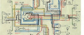
Original wiring Java 634: operating tips
The Czechoslovakian brand JAWA is well known in the USSR. Its two-wheeled motorcycles have become a revered and respected standard for motorcycle enthusiasts throughout the country. And this despite the fact that in our harsh conditions, Java 634 wiring and other electronic components often failed. Legendary JAWA 350/634
Motorcycles of this brand first appeared in the USSR in 1973 and were sold at a fairly high price (the price started from 950 rubles, depending on the region). A couple of years later, instead of the “634th” model, which had 6V equipment, Czechoslovak motor builders proposed a new generation - “638”, transferred to more promising 12-volt equipment.
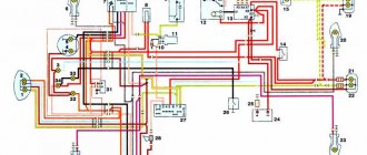
Note! It should be noted that there was a shortage of spare parts for motorcycles. Even a detailed wiring diagram for the Java 634 (shown in the photo below) was considered a great success when buying a motorcycle second-hand.
Color scheme for the 6B version of the JAWA motorcycle
Operational Features
It was the motorcycle in our country that became a clear confirmation that a two-wheeled vehicle is truly a means of transportation.
- In the forest thicket;
- In the mountains;
- On city highways;
- In the rural outback;
- At sports competitions, etc.
Its endurance and reliability on the longest routes contributed to the high popularity of the brand as a whole. Even the resale of a 5-year-old copy brought the former owner at least 500 rubles.
For reference: Purchasing new domestic two-wheeled motorcycles cost more modest sums for the family budget. The shortage of spare parts, missing instructions and minor breakdowns did not stop me from buying my dream motorcycle.
- In private garages;
- In the back rooms;
- On the balconies;
- In apartments, etc.
Motorcycle electrical equipment
Despite the high build quality and durability of the main components and assemblies, the technical condition of the motorcycle had to be constantly monitored.
- Battery;
- Ignition systems;
- Fuel supply systems;
- Lubrication systems.
Battery
- Checking the electrolyte level in each cell;
- Checking its density (nominal value - 1.26 g/cm3);
- Charging the battery when the discharge at the terminals decreases below the permissible values (when fully charged, the voltage is 7.8-8.1 volts). The battery is charged with a current of 0.6 A.
Ignition adjustment Java 638
The Czechoslovak motorcycle has a number of advantages compared to other Soviet units, but is almost the same in terms of electrical equipment. The JAVA 638 wiring diagram is quite simple. Even an inexperienced motorist can handle repairs and maintenance.
Adjusting the ignition of the JAVA 638 is very important for the correct operation of the engine. You can do it yourself at home. To do this you need:
- Remove the spark plugs from both cylinders and remove the sump cover.
- After removing the spark plugs, install the indicator in the hole of the right cylinder.
- Now you need to fix the piston at top dead center. To do this, turn the crankshaft using a key.
- Then the cylinder contact spacing is adjusted. They should only touch slightly (a distance of approximately 0.35 millimeters).
- A light bulb is connected to the contact on which the advance is set. This is done before setting up the ignition on the JAVE 638, to accurately measure the distances between the contacts.
- Zero is measured on the indicator, after which the position is fixed.
- The advance is different for each gasoline. So, when using the 92nd and 95th, the adjustment is 2.7-3.1 millimeters, for the 80th – 2.9-3.3 millimeters.
- If the installation is correct, the light goes out. Otherwise, adjustment will be carried out by a movable disk.
- An identical procedure is carried out on the other cylinder.
- When the adjustment is completed, crank the crankshaft several times using the kickstarter. Then the control ignition advance is performed. This completes the YAVA 638 ignition installation.
It is important to understand that if the ignition is incorrectly measured, the engine's operating life will be reduced.
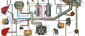
Electrical diagram
The electrical circuit of the YAVA 638 has been modernized based on the wiring of the previous model. The experimental 12-volt equipment was completely replaced and required the installation of a more capacious battery. Features of this innovation:
- the appearance of a 210-watt generator;
- possibility of installing an additional fog lamp;
- The stroller consumers were provided with current from a standard generator.
Thanks to the new system, the level of luminous flux was increased, which ensured driving safety at night. Spark formation has also improved, which contributes to more uniform and dynamic engine operation.
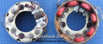
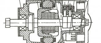
The new generator contains such basic elements as a rotor, stator and a metal casing. Its efficiency significantly exceeds the previously used 6-volt generator. This system allows charging even when the engine is running at low speeds.
However, the created system generated direct current, which needed to be converted into alternating current. For this purpose, a rectifier was built into the system. Its convenient location under the saddle makes it easy to carry out maintenance yourself.
However, when installing such equipment, the problem of overheating of the generator walls arose. It became impossible to use the rectifier inside a metal casing, so it was located under the driver's seat, providing air flow to cool the system.
The permissible power to a temperature of 150 degrees Celsius was 15 amperes. With the stroller and the use of all devices, it became possible to connect one additional consumer that does not require more than 40 watts of power.
Unfortunately, using a motorcycle in high temperature conditions of more than 30 degrees can lead to electrical equipment failure. For example, if the YAVA 638 does not start, there is a high probability that the stator winding has overheated or even the insulation has been damaged.
In general, we can say that innovations in the motorcycle have had a good effect not only on electricity consumers. Thanks to the new spark supply system, the engine began to work more evenly, as a result of which the bike became more dynamic. We can say that this unit was one of the best on the Soviet market.
We recommend reading:
(Rate this article)
motoholder.ru
What will you need?
To install the ignition from a scooter in Java, we will need a specific conversion kit. First of all, there is the generator itself; there are two models to choose from. The simpler QMB-139 will perform all the necessary functions, but problems may arise with the light at night, since the winding for the head light is rather weak and will greatly depend on the speed. If this parameter is important to you, then choose a stator from the QMI-157 or 152QMI model - they will be sufficient to achieve your goals.
Contactless ignition system (BSZ Java)
While writing the article, I sat and thought and thought, and still did not come to the conclusion of what exactly is the main advantage of BSZ; for me, all the advantages listed below are the main ones and are equal to each other.
So let's get started:
— High stability of engine operation (synchronous operation of the cylinders, strictly in turn)
— Frisky review of the throttle
— Better engine thrust (which allows you to easily use the largest drive stars without difficult acceleration!)
— Candles “live” four times longer than on KSZ (I’ll write about this separately below)
— Less well-known “snot” from Java mufflers (since fuel and oil are burned much better)
— Longer service life of all crank bearings (as there is less extraneous detonation and vibration)
— Less fuel consumption (since it burns better, the carburetor must be adjusted to a lower fuel supply)
Types of BSZ
There are two types of BSZ:
— Single-channel (one Hall sensor, two-lobe modulator, one switch, one two-terminal ignition coil operating on two cylinders at once)
— Two-channel (two Hall sensors, one, or better yet two, modulator lobe, two switches, two ignition coils, one for each cylinder)
It is preferable to install a single-channel system, since it will be more stable, because here you do not have to adjust each cylinder (which you have to do at KSZ); here, if the modulator is properly made, then only one cylinder is adjusted. Also, in a single-channel one, fewer wires are used, its parts take up less space, and energy consumption is lower (which is very important for 6-volt generators)
There are many people who like to “get confused” who install a two-channel one, shouting at the same time that this way they can configure it more accurately, etc. I assure you that these are unnecessary hassles, and there will be no accuracy here (why is indicated above)
Spark plug. I said above that spark plugs “live” longer, which begs the question “Why?”
Actually the answer is simple. If you decide to install a single-channel BSZ (or a two-channel one with a two-lobe modulator), then this is what will happen:
When igniting in one cylinder, in the other, a spark will also strike at BDC, since it strikes simultaneously on both spark plugs, that is, spark twice per revolution on each spark plug.
What does this give? This allows for warming up and cleaning of the spark plugs at that moment the pistons are at bottom dead center, we get a smaller temperature difference between the spark plug electrodes (not allowing it to cool) and clean electrodes, ready for the new ignition of the fuel mixture. These factors, as practice has shown, increase the service life of candles.
PS Please note that spark plugs must be used exactly those that are designed for BSZ (when purchasing at a car store, you must indicate this to the seller)
INSTALLATION OF BSZ
To do this, you need to prepare the following in advance:
- tools: screwdrivers, pliers, hammer, anvil, multimeter (preferably electronic), narrow ruler (up to 10mm wide) or calipers, file and needle files
— parts: switch (VAZ-2108), Hall sensor, connecting wire harness for them (ready-made for sale), two-terminal ignition coil from Gazelle or Oka, modulator (butterfly is made of magnetic metal 0.7-1 mm thick according to the drawing below) high-voltage wires (armored wires) high power (preferably silicone)
Butterfly modulator (drawing)
1.Initial stage
First, let's make a modulator if you haven't already made one. The easiest way to do this is to print out the drawing in real size (the dimensions of the drawing correspond to real measurements), stick the printout on a metal plate and cut out the modulator along the contours of the drawing. ATTENTION!!! Millimeter precision is important here! So no “in-your-face” behavior should be allowed here!!! The edges of the modulator must be processed with a file so that there are no nicks or burrs.
2.Dismantling
— Disconnect the high-voltage wires from the spark plugs.
— Disconnect the inductor wires from the ignition coils
— Remove the ignition coils along with the high-voltage wires (we won’t need this anymore)
— Disconnect the capacitors from the breaker contacts
— Disconnect the inductor wires from the breaker contacts
— Remove the contacts from the ignition plate
— Unscrew all the screws from the ignition plate and remove it from the generator
3.Preparation
— Place the anvil on a flat surface
- Place the ignition plate on the anvil and smooth out all the bends with a hammer, and remove the breaker pins with pliers
— Unscrew the generator rotor bolt
4.Installation
— Hang the 2-pin ignition coil in a convenient place under the tank
— Connect wires 1 and 4 of the switch to the coil as shown in the diagram, as well as high-voltage wires to the spark plugs (ATTENTION!!! DO NOT USE HIGH-VOLTAGE WIRES FROM YOUR OLD COILS!!! FOR ELECTRONIC IGNITION YOU NEED POWERFUL WIRES, PREFERABLY SILICONE, SOLD IN ANY CAR STORE!)
— Screw the modulator to the rotor with a standard armature bolt
— Attach the Hall sensor to the plate as shown in the photo
— Secure the switch in a place convenient for you (it is recommended to install it on the right cover of the air cleaner directly under the facing cover)
— Lay the connecting wires of the switch and the DC and connect to the switch and the DC
— Ground wire 2 of the switch to the motorcycle frame (do not ground to the tank!)
5.Adjusting the ignition timing (IPA)
5.1. Set the left piston to top dead center, and using a ruler (or caliper) move the piston back 3mm
5.2. Loosen the generator bolt securing the modulator (ATTENTION DO NOT ALLOW THE SMALLEST ROLL OF THE CRANKSHAFT!!!)
5.3. Connect the multimeter like this: the red clamp to the green wire of the hall sensor (at the input to the sensor from the green wire, you need to move the white heat shrink and gain access to the bare wire), and connect the black clamp of the multimeter to ground (for example, to the engine crankcase)
5.4. Set the multimeter to read voltage in the range of 0-20 volts
5.5. Turn on the ignition (the multimeter should show a value either equal to or close to zero)
5.6. Rotate the modulator very slowly so that its metal enters the Hall sensor while keeping an eye on the multimeter!
5.7. As soon as a reading of 4-12 volts appears on the multimeter, stop rotating the modulator, and turn it even more slowly in the opposite direction so that the device just shows zero again!
5.8. Tighten the alternator bolt WITHOUT TURNING THE MODULATOR AND CRANKSHAFT!
5.9. Check the position of the piston again and recheck the position of the modulator and the readings in this position of the device when it is tightened; if the readings deviate, then adjust by loosening the screws securing the plate with the DC and slowly rotate the entire plate until the readings are correct.
5.10. Check the readings for the right piston, only if the readings deviate, do not move anything from its place (neither the plate nor the modulator), but use a file to sharpen the edge of the modulator that enters the Hall sensor at this moment.
6.Launch
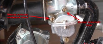
— If your motorcycle has a float suppressor on the carburetor, then press it and hold it until fuel starts to drip from the carburetor, but if your motorcycle does not have a float suppressor, but has a cold start mechanism (for example, a Mikuni or Jikov carburetor as on the Java 638), then raise the flag and pump up three or four times using kickstarter.
— Insert the key into the “ignition” position and sharply pull the kickstarter
If you have internet at normal speed, then watch our three videos on BSZ to make it more clear how all this is done, including on a motorcycle with 6-volt electrical equipment!
Watch video https://www.youtube.com/playlist?list=PLz0PatQPn4PFLhn2zSBKqyRdrKdexY_QR
Material provided by: A. Mishura.
extreme.newline.by