Braking torque
There is probably no point in talking about the importance of proper brakes on a motorcycle.
But in order for the brakes to work properly, they need to be serviced. This is what we will talk about. There are two types of brakes installed on motorcycles: drum or disc. Mechanical drum brakes are, of course, a thing of the past. Today, advanced disk drives set the tone, but, nevertheless, the “drum”, due to its low cost, will still be used for some time on small-capacity and domestic equipment. In this article (continued) we will look at both designs.
Tenacious archaism
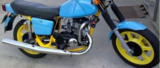
Drum mechanisms were installed on almost all Soviet production motorcycles, which are still quite widely used in the vast expanses of our Motherland, as well as on some imported scooters, small-capacity (125-250 cm3) motorcycles (usually as a rear brake).
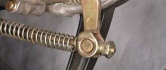
The drum brake (Fig. 1) consists of a drum (1), which is attached to the wheel hub with rivets or is cast with the hub. Outside the drum there are cooling fins. There is a support disk (2) inside. It is fixedly attached to the motorcycle suspension elements (fork leg, pendulum). Two pads (3) with friction linings (4) are mounted on it. The pads are made of steel or aluminum. The task of the linings is to provide good friction, but at the same time be resistant to rapid abrasion, not deform or melt. Previously, the linings were made of asbestos, with inclusions of brass or copper, but nowadays only asbestos-free materials are used. Each block rests against the stop (5) at one end, and against the expansion cam (6) at the other, and they are pulled together by one or two springs (7). The cam is connected with the lever on the steering wheel or the rear brake pedal (9) using levers (8), rods, or a cable.
When you press the lever (or pedal), the cam rotates, pressing on the pad bearings. The pads move apart and are pressed against the drum, braking occurs. If no force is applied, the pads return to their original position under the action of springs. The design is simple and quite reliable, but the single-cam brake does not work at its best. The fact is that when braking, one pad rotates in the direction of rotation of the wheel and is usually called “primary” or “active”, and the other one rotates against rotation, and is called “secondary” or “passive”. And that's why. Let's look at Figure 2. The pads are moved apart by driving forces F1 and F2; let's assume that they are equal. Friction forces R1 and R2 arise between the pads and the drum. The moment of force R1 relative to the block support acts in the same direction as the moment of force F1 and increases the pressing of the primary block. The moment of force R2 is directed in the opposite direction (relative to the moment of force F2) and, therefore, weakens the pressing of the secondary block to the drum. In simple words, the friction force additionally presses the primary shoe against the drum, creating a self-pressing effect, while the secondary shoe “tries” to push itself away from the drum. Hence the main drawback of this design is the large difference in the performance of the pads. Some single-cam brakes have another drawback - the cam presses on the pad thrust bearings at different distances from the center of rotation (the moments of force F1 and F2 are not the same), therefore, again, the pressing forces of the pads are different (Fig. 2).
You can make the brake more “strong” without increasing the size of the drum by using a two-cam mechanism (Fig. 3). At the same time, braking efficiency will increase by 30%. The two-cam brake began to be actively used at the beginning of the second half of the last century as a front brake, the rear one remained single-cam. The brakes of “our” motorcycles were made according to the same scheme: IZH-Jupiter-5, MT-10-36, Dnepr-11, Dnepr-12, Dnepr-16, KMZ-8.157, Java 634 and 638.
The fact is that when a motorcycle brakes, weight is redistributed over the wheels, the front wheel is additionally loaded, so the front brake should be more effective. The two-cam brake is more efficient due to the fact that it has both primary pads (Fig. 3). The drive and synchronization of the two cams is carried out by a lever mechanism.
But all the advantages of the brake can come to naught without proper care and adjustments. Let's start with the fact that every 5000 km all cables and hinges must be lubricated. For this purpose, it is better to use Litol-24 or other greases, but very carefully. After all, excess heated lubricant can get on the pads and drum! The danger is the same as with excess grease in the wheel bearings. If this happens, the drum and pads should be washed in gasoline, but if the linings have absorbed the lubricant to some depth, they should be wiped with emery cloth and then washed in gasoline. The cable should be lubricated with viscous oil or brake fluid. The cable is dipped into a container with oil (for example, MS-20) and the sheath is then moved (5-10 times) along the cable. Let the oil drain and wipe the casing dry.
For the brake to work effectively, it must be adjusted. This is mainly due to wear on the linings.
The single-cam brake of the rear wheel is adjusted by a screw located in the rear wheel sprocket housing (IZH-Jupiter-5, IZH-Planeta-5). On motorcycles “Dnepr” and “Ural” the brake is adjusted using an adjusting cone. The free travel of the pedal is set to 10-15 mm, and the wheel should be blocked at a travel of 75-100 mm.
On a Java 350/368 motorcycle, the rear brake is adjusted by rotating the impeller. The impeller is tightened until the block begins to slow down, and then it is loosened by 1.5 turns. In any case, when the brake is released, the shoes should not touch the drum, and if the position of the pedal can be adjusted, then install it so that it is always under your foot, and you can press it without removing your foot from the footrest.
If a single-cam brake is installed on the front wheel (Fig. 4), as, for example, in the IZH-Jupiter-3, then adjust it with the screw (1) located on the support disk. By screwing it in or out, you should achieve a free play of the end of the lever on the steering wheel of 5-10 mm. If the brake cannot be adjusted in this way and the wheel does not brake, turn the cam lever to 1 spline.
As for two-cam brakes, they are regulated somewhat differently. For example, adjusting the front brake Java 350/638 (Fig. 5). First, loosen the cable impeller (1), then loosen the connecting rod of both shoes (2). Tighten the impeller until the block begins to slow down. Then you should loosen the impeller 1.5 turns. Tighten the connecting rod nut until the pads begin to rub, then loosen it 1.5 turns. Adjust the free play of the control lever (5-10 mm) by rotating the impeller.
But sometimes adjusting the brakes cannot return them to working order; they require repairs.
The most common type of repair is replacing the pads. Sometimes new pads are riveted onto old pads. On some motorcycles, the degree of wear of the linings can be monitored by the wear indicator arrow (Fig. 6).
But no matter how simple it may seem to replace the pads, sometimes you have to tinker with them. New linings have a reserve in thickness and do not want to fit into the drum. This is done so that they fit into a worn or bored drum. Therefore, they will have to be cut down, and then, after some running-in, they will rub in and work normally.
Sometimes replacing pads does not lead to the desired result. What is the reason? Most often, deep grooves and risks on the inner surface are to blame. The worn surface is restored by boring and grinding. If the motorcycle has been standing for a long time, rust may appear on the working surface of the drum. It is cleaned with emery cloth and gasoline.
Typically, brake performance decreases gradually as it wears out. But sometimes the brake “disappears” instantly. The most obvious reason is a broken cable. Sometimes the splines on the cam shaft become wrinkled. Brakes can also fail if water gets on the pads. The brake may also jam - this happens when a spring breaks or flies off. Then the primary block, carried by the drum, jams. Sometimes jamming can also occur due to a weak spring and high friction forces in the brake mechanism, but even a “strong” spring will not be able to release the brake if it is not lubricated.
As for drum brakes, their age is over. Motorcycles have become more powerful and dynamic, and the drum brake has fallen behind in power and efficiency, and has passed the baton to the powerful and durable disc brake. With the massive entry of Japanese models into the world market, disc brakes began to rule the roost.
New era
1969 marked the beginning of the release of the Honda CB 750, and it was destined to usher in a new stage in the development of the motorcycle. This was the first mass-produced “Japanese” with an inline “four”. The engine had an overhead camshaft, dry sump, and four carburetors. The engine was started with a starter, which was very rare at that time. No less rare was a five-speed gearbox made in the same unit with the engine and... a front wheel disc brake with a hydraulic drive!
The disc brake was invented by British designer Frederick Lanchester and was first used back in 1903 on a car. Later it was installed as a transmission (parking) brake on trucks and buses. Well, it was first used as wheel brakes in aviation, where it proved excellent due to its efficiency. The first production car to be equipped with disc brakes on all wheels was the Jaguar XK 150 in 1957.
But let's leave cars and planes alone and get back to motorcycles. Of course, before 1969 there were attempts to equip a motorcycle with a disc brake, but these were isolated cases, mainly on sports motorcycles. And in 1967, the MV Agusta 600 motorcycle, also with a disc brake, but with a cable (mechanical) drive, began to be produced in small series. Its effectiveness was so low that it was soon abandoned and they returned to the “drum”. So the Honda CB 750 was the first production motorcycle with an efficient disc brake, which later retired the drum brake. The first Soviet production motorcycle with a front disc brake in 1990 was the IZH-7.107-015 “Planet-5”.
Initially, a disc brake was installed on the front wheel, as it was more effective, while the rear one remained a drum brake, since when braking, up to 75% of the motorcycle’s weight fell on the front wheel. Later, the rear “drum” was replaced with a “disc”, but there was no point in making it as powerful as the front one, so it is much weaker. But a more effective option was to install two discs on the front wheel and a single disc brake at the rear. However, single-disc front brakes are still quite common, as are rear drum brakes. The advantages of disc brakes over drum brakes are obvious.
First, disc brakes cool better and allow the bike to slow down more quickly. Secondly, they are lighter, which reduces unsprung mass and the gyroscopic effect. But to press the pads to the disc, more force is required, and since disc brakes do not have a self-reinforcing effect, like drum brakes, therefore, a hydraulic drive is used in disc brakes. Why hydraulic drive? The thing is that the liquid does not compress; it is easy to transmit force with its help. But the main thing is that in the hydraulic system it is possible not only to transmit force, but also to increase it, thanks to the different diameters of the pistons of the main and working cylinders (Fig. 7).
So, if the diameter of the piston of working cylinder 2 is twice the diameter of the piston of main cylinder 1, then the force will be increased by 4 times. If the diameter of the working cylinder piston is three times larger than the diameter of the master cylinder piston, then the force will increase by 9 times! And so on. But the larger the working cylinder piston is compared to the main cylinder piston, the less it will move relative to the movement of the master cylinder piston. After all, the volume of liquid transferred does not change! However, it is not difficult to make the hydraulic brake drive system such that the movement of the pistons, and even more so, the force will be enough to stop the motorcycle. The main thing is to find the “golden mean” so that the bike stops quickly and the wheel does not lock when you lightly press the brake lever.
Brake fluids “work” in the hydraulic brake drive. Currently, liquids of classes DOT-3, DOT-4, DOT-5 and DOT-5.1 are used.
Brake fluids DOT-3, DOT-4 are made on a polyglycol base, and they can be mixed with each other in any proportions; in addition, they absorb moisture, that is, they are hygroscopic. This means that the more water there is in the brake fluid, the lower its boiling point will be. That is why the boiling point of “dry” and moisture-containing liquids is indicated (Table 1). Therefore, a “damp” liquid can boil at the most inopportune moment. A few intense decelerations are enough for compressible vapor bubbles to appear in the incompressible liquid. The brakes will “disappear”, we won’t talk about the consequences...
Liquids DOT-3, DOT-4 and DOT-5.1 are painted yellow to distinguish them from liquid DOT-5, which is made on a silicone base and has a dark red color. DOT-5 cannot be mixed with polyglycol-based brake fluids - a sediment will form. It does not mix with water either. Any brake fluid should be protected from water and dirt getting into it. It “pulls” moisture even from the air, deteriorating its performance over time. Any brake fluid must be changed at least once every two years, and which fluid should be used for a particular motorcycle is decided by the manufacturer.
We will return to the topic of brake fluid (replacing, bleeding brakes), and also consider design options for modern disc brakes, but we will do this in the next issue of the magazine.
Source
IZH hydraulic brake: description
IZH PLANET 5, IZH JUPITER 5-01
In the domestic motorcycle industry, serial production and equipping of motorcycles with disc brakes began with the IZH Planet 5 motorcycle in configuration 015. The use of disc brakes made it possible to obtain high stability of the braking characteristics of the motorcycle as a whole and a significant reduction in labor intensity during operation.
The hydraulic disc brake consists of a master cylinder located on the right side of the handlebar, a brake caliper attached to the left front suspension movable tube, a hydraulic hose connecting the master cylinder to the brake caliper, and a brake rotor mounted with six bolts on the left side of the front wheel.
The brake master cylinder, mounted on the right side of the motorcycle handlebar using a bracket with two screws, consists of a cylinder body, in the upper part of which there is a reservoir for brake fluid, closed with a lid. The cover is secured with screws. The seal between the body and the cover is made by a diaphragm. In addition, the diaphragm acts as a buffer and serves to equalize the pressure that changes in the master cylinder reservoir when the piston with cuffs moves. The level of brake fluid in the reservoir is monitored through a level indicator installed in the cylinder body through an o-ring. At the bottom of the cylinder body there is a piston unit connected to the reservoir through two holes. The piston assembly consists of a piston with cuffs and fixed in the main cylinder body using a retaining ring and a valve closed with a protective cover, a return spring and a thrust washer. The movement of the piston assembly and, therefore, the operation of the entire main cylinder is controlled by a double-arm drive lever.
To signal that the front brake is engaged, a switch is installed in the master cylinder housing.
When the driver presses the drive lever, the lever, turning, releases the contact of the switch and, thus, sends a signal to the rear light to turn on the front brake, and the force begins to be transmitted through the double-arm lever and the heel to the piston. The piston, moving, closes the connection with the master cylinder reservoir with a cuff and begins to compress the fluid, which is located in the space above the piston, and move it through the outlet hole into the brake hose. In the brake hose, depending on the force applied to the lever, pressure arises, which is transmitted to the brake caliper. The piston returns to its original position by means of a return spring, and the liquid flows through the valve. The main working element of the master cylinder is the main cuff, with the help of which pressure is created in the system and the performance of the entire system depends on the condition of which.
The next element of the brake system is the brake hydraulic hose, which connects the brake master cylinder to the brake caliper. The brake hose consists of a hose, two ends, which, using special bolts and sealing washers, connect the hose to the brake master cylinder and brake caliper. The upper connection, i.e. the connection between the brake hose and the brake master cylinder, is covered with a protective cover.
The front brake caliper consists of a shoe guide, a guide pin, a caliper body, a brake pad, a latch, a piston with an O-ring and a piston boot with a retaining ring, and an air release valve with a protective cap. This design of the front brake caliper is called “floating”, since the pad guide is rigidly attached with bolts to the left movable pipe of the front suspension, and the caliper itself, relative to the guide, moves along the guide pin with a protective cover. Thus, the brake caliper, together with the “floating” brake pads, selects a position that ensures a uniform minimum gap between the brake pads and the brake disc, both to the left and to the right of the brake disc. When you press the handbrake lever, pressure is applied through the brake hose to the caliper between the piston and the caliper body, causing the piston to move and transmit force to the brake pad. The piston moves within the elastic deformation of the sealing ring. The pads move closer together and clamp the brake disc together. The clamping force of the brake disc depends on the force applied to the handbrake lever. The return of the pads to their original position and the establishment of the required gap after removing the forces on the handbrake lever occurs due to the elastic properties of the rubber from which the o-ring is made. This floating caliper design with a moving piston allows you to always have the same clearance between the brake pads and the brake disc. When the brake pads are worn (their condition can be monitored through the indicator cover), the gap between the brake disc and the pads is automatically maintained within the required limits due to the movement (slipping) of the piston relative to the sealing ring when force is applied to the handbrake lever.
During the assembly process, the entire system is filled with 200 g of Tom brake fluid and pumped to remove air pockets and bubbles from the system.
During operation, it is necessary to monitor the presence of brake fluid in the system. Control is carried out through a level indicator located on the brake master cylinder. Brake fluid monitoring must be carried out before each departure, for which the motorcycle is placed on a central stand on a horizontal section of the road, the steering wheel must be in the straight driving position, and the brake fluid level in the brake master cylinder must be slightly higher than the average diameter of the fluid level indicator. If this level is lower, it is necessary to add brake fluid. To do this, you need to unscrew two screws, remove the cover and diaphragm, add fluid to the required level and reassemble in the reverse order.
It is also necessary to ensure that fluid does not leak from the entire hydraulic drive system. In the event of a leak, it is necessary to determine the location of the leak and eliminate it. If there is a leak in the places where the hydraulic hoses are attached to the cylinder or bracket, the connection must be tightened. A leak is also possible due to excessive wear of the seals in the brake master cylinder or due to failure of the seal in the brake caliper. In both cases, the leak is eliminated by replacing parts. To replace the cuffs in the brake master cylinder, you need to remove the lever, take out the protective cover, use a special tool in the form of tweezers or sharpened scissors to remove the retaining ring and then remove the piston with the cuffs. Replace the worn cuff with a new one and reassemble in the reverse order. If there is a leak through the brake caliper seal, which is very rare, it is necessary to remove the caliper from the motorcycle, remove the brake pads from it, carefully remove the protective boot, remove the piston and O-ring. Replace worn parts and reassemble in reverse order. In all cases, after replacing brake system parts and assembling, the system must be filled with fluid and pumped.
Brake pad wear should be monitored. The thickness of the asbestos mass molded to the block reinforcement is 7 mm. During operation, it is allowed to reduce the thickness of the asbestos mass to 1 mm, after which the brake pads must be replaced. To change the pads, you need to unscrew the bolt securing the bracket to the guide and rotate the bracket, moving it out of the brake disc area. Remove the brake pads, replace them with new ones, carefully push the piston inside the caliper using a mounting blade and reassemble.
In an adjusted and working hydraulic disc brake, when pressing the handbrake lever after selecting free play (15...25 mm), the driver should feel a hard stop. The absence of such a stop (the feeling of the lever “sinking”) indicates a malfunction in the system. The reason for the failure of the lever may be the presence of air in the hydraulic system (the system is not pumped) or excessive wear of the main cuff in the master cylinder of the brake.
Bleeding the system is performed in the following order:
— fill the reservoir of the brake master cylinder with fluid to the recommended level (the filling procedure was given above);
— clean the air release valve on the brake caliper from dust and dirt and remove the rubber protective cap from the riveting head;
— place a rubber hose on the valve head, immerse the free end of the hose in brake fluid poured into a clean glass container with a capacity of at least 0.5 liters, filled to half its height;
- sharply press the hand brake lever with your hand sequentially 3 ... 4 times with an interval between pressing 1 ... 2 s, and then, leaving the lever pressed, unscrew the air release valve by 1/2 ... 3/4 of a turn, while in the flowing liquid will appear air bubbles;
— after liquid has stopped flowing out of the hose, screw the air release valve all the way;
- repeat the last two operations until the release of air bubbles completely stops.
When removing air from the hydraulic drive system, constantly monitor the brake fluid level in the master cylinder reservoir and do not allow the level to drop more than 2/3 of the normal value.
After the air release from the hose has completely stopped, keep the handbrake lever pressed, screw the air release valve as far as it will go and only then remove the hose from its head. Next, put a protective cap on the valve head and add liquid to the normal level.
ATTENTION! The brake fluid released into the vessel when pumping the system can be reused for refueling only after it has settled (at least 24 hours) until the air contained in it has been completely removed and has been filtered.
TECHNICAL CHARACTERISTICS OF HYDRAULIC DRIVE OF FRONT WHEEL DISC BRAKE
| Master cylinder diameter, mm | 15,8 |
| Piston stroke, mm | 16 |
| Working cylinder diameter, mm | 38,1 |
| Friction lining dimensions: | |
| width, mm | 35 |
| thickness, mm | 7,0 |
| total area, cm2 | 38 |
| Brake disc dimensions, mm: | |
| thickness | 5 |
| outer diameter | 298 |
| Effective friction radius, mm | 133,5 |
| Brake fluid volume, l | 0.2 |
| 1. Drive lever 2. Level indicator 3. Master cylinder cover 4. Hose 5. Bracket 6. Cylinder body 7. Plate 8. Cover 9. Diaphragm 10. Screw 11. Protective cover 12. Retaining ring 13. Cuff 14. Piston 15 Valve 16. Main cuff 17. Thrust washer 18. Spring 19. Shoe guide 20. Latch 21. Brake pad 22. Anti-squeak plate 23. Piston boot 24. O-ring 25. Piston 26. Brace body 27. Bolt 28. Protective cover 29. Guide pin 30. Air release valve (cap) 31. Indicator cover 32. Bolt 33. Bushing 34. Bushing 35. Spring |
Front Brake Adjustment
1. Place a blank under the engine crankcase so that the front wheel does not touch the ground.
2. Unscrew locknut 1 (Fig. 31) of adjusting screw 2 several turns.
3. Rotate the adjusting screw until you obtain a free play of the brake lever equal to one third of its full travel. When the adjusting screw is screwed in, the free play of the lever increases, and when turned out it decreases.
4. Check the adjustment in place and while the motorcycle is running.
5. Lock the adjusting screw.
In the event that further unscrewing of the adjusting screw is impossible, adjust the front brake in the following order:
1. Unscrew the locknut of the adjusting screw until it fails.
2. Tighten the adjusting screw to three-quarters of its length.
3. Loosen bolt 3 holding the brake cable to the brake lever.
4. Pull the cable and secure it to the lever with a bolt.
5. Adjust the brake using the adjusting screw.
Rear brake adjustment
1. Place the motorcycle on the rear stand.
2. Unscrew the locknut 5 (Fig. 30) of the adjusting fork 6 of the left brake rod.
3. Unscrew the nut of the bolt securing spring 7 of the brake light switch to the brake rod, disconnect the spring from the rod.
4. Unscrew and remove connecting pin 8 of the left brake rod.
5. By rotating the adjusting fork, adjust the length of the rod so that, when put in place, it provides free play of the brake pedal equal to one quarter of its full travel.
6. Replace the rod with the adjusting fork and the connecting pin and tighten the lock nut of the adjusting fork.
Attach the brake light switch spring to the brake rod so that the brake light comes on when braking begins.
7. Check the results of the adjustment in place and while the motorcycle is running.
Note. If it is impossible to adjust the brake by changing the length of the left rod, then the right brake rod, which has an adjusting fork at the rear end, should be additionally shortened or lengthened.
ADJUSTING WHEEL BEARINGS
The adjustment should ensure free rotation of the wheel without play in the bearings.
Front wheel
1. Place the motorcycle on the rear stand. Place a blank under the engine crankcase so that the front wheel does not touch the ground.
2. Unscrew and unscrew the left nut 1 (Fig. 32) of the wheel axle.
3. Bend the edges of lock washer 2 and unscrew locknut 3 on the left side of the axle.
Rice. 32. Adjusting the front wheel bearings:
1 - wheel axle nut; 2 - lock washer; 3 - lock nut; 4-hub bushing nut; 5-adjusting nut
4. Holding the bushing nut 4 on the right side of the wheel hub with a wrench, tighten the adjusting nut 5 on the left side until the play in the bearings is eliminated. The wheel should rotate freely on the axle.
5. Tighten the locknut and axle nut. Bend the edges of the lock washer and tighten the axle nut.
6.Check the adjustment results; When the wheel rocks sideways, there should be some play and the wheel should rotate freely.
Rear wheel
1. Place the motorcycle on the rear stand.
2. Unscrew nut 1 (Fig. 33) of the wheel axle by six to seven turns.
3. Bend the edges of the lock washer 2 of the adjusting nut 3 (on the right side of the wheel hub).
4. Hold the adjusting nut with a wrench and unscrew locknut 4 one or two turns.
Rice. 33. Adjusting the rear wheel bearings:
1-wheel axle nut; 2-lock washer; 3- adjusting nut; 4-lock nut
5. Tighten the adjusting nut until the play in the bearings is eliminated. The wheel should rotate freely on the axle.
6. Hold the adjusting nut with a wrench, tighten the locknut and bend the edges of the lock washer.
7. Tighten the wheel axle nut.
8. Check the result of the adjustment: when the wheel rocks sideways, there should be no play, and the wheel should rotate freely.
Single-post wooden support and methods for strengthening corner supports: Overhead line supports are structures designed to support wires at the required height above the ground and water.
Transverse profiles of embankments and coastal strips: In urban areas, bank protection is designed taking into account technical and economic requirements, but special importance is given to aesthetic ones.
Papillary patterns of the fingers are a marker of athletic abilities: dermatoglyphic signs are formed at 3-5 months of pregnancy and do not change throughout life.
Source
Front Brake Adjustment
1. Place a blank under the engine crankcase so that the front wheel does not touch the ground.
2. Unscrew locknut 1 (Fig. 31) of adjusting screw 2 several turns.
3. Rotate the adjusting screw until you obtain a free play of the brake lever equal to one third of its full travel. When the adjusting screw is screwed in, the free play of the lever increases, and when turned out it decreases.
4. Check the adjustment in place and while the motorcycle is running.
5. Lock the adjusting screw.
In the event that further unscrewing of the adjusting screw is impossible, adjust the front brake in the following order:
1. Unscrew the locknut of the adjusting screw until it fails.
2. Tighten the adjusting screw to three-quarters of its length.
3. Loosen bolt 3 holding the brake cable to the brake lever.
4. Pull the cable and secure it to the lever with a bolt.
5. Adjust the brake using the adjusting screw.
Rear brake adjustment
1. Place the motorcycle on the rear stand.
2. Unscrew the locknut 5 (Fig. 30) of the adjusting fork 6 of the left brake rod.
3. Unscrew the nut of the bolt securing spring 7 of the brake light switch to the brake rod, disconnect the spring from the rod.
4. Unscrew and remove connecting pin 8 of the left brake rod.
5. By rotating the adjusting fork, adjust the length of the rod so that, when put in place, it provides free play of the brake pedal equal to one quarter of its full travel.
6. Replace the rod with the adjusting fork and the connecting pin and tighten the lock nut of the adjusting fork.
Attach the brake light switch spring to the brake rod so that the brake light comes on when braking begins.
7. Check the results of the adjustment in place and while the motorcycle is running.
Note. If it is impossible to adjust the brake by changing the length of the left rod, then the right brake rod, which has an adjusting fork at the rear end, should be additionally shortened or lengthened.
ADJUSTING WHEEL BEARINGS
The adjustment should ensure free rotation of the wheel without play in the bearings.
Front wheel
1. Place the motorcycle on the rear stand. Place a blank under the engine crankcase so that the front wheel does not touch the ground.
2. Unscrew and unscrew the left nut 1 (Fig. 32) of the wheel axle.
3. Bend the edges of lock washer 2 and unscrew locknut 3 on the left side of the axle.
Rice. 32. Adjusting the front wheel bearings:
1 - wheel axle nut; 2 - lock washer; 3 - lock nut; 4-hub bushing nut; 5-adjusting nut
4. Holding the bushing nut 4 on the right side of the wheel hub with a wrench, tighten the adjusting nut 5 on the left side until the play in the bearings is eliminated. The wheel should rotate freely on the axle.
5. Tighten the locknut and axle nut. Bend the edges of the lock washer and tighten the axle nut.
6.Check the adjustment results; When the wheel rocks sideways, there should be some play and the wheel should rotate freely.
Rear wheel
1. Place the motorcycle on the rear stand.
2. Unscrew nut 1 (Fig. 33) of the wheel axle by six to seven turns.
3. Bend the edges of the lock washer 2 of the adjusting nut 3 (on the right side of the wheel hub).
4. Hold the adjusting nut with a wrench and unscrew locknut 4 one or two turns.
Rice. 33. Adjusting the rear wheel bearings:
1-wheel axle nut; 2-lock washer; 3- adjusting nut; 4-lock nut
5. Tighten the adjusting nut until the play in the bearings is eliminated. The wheel should rotate freely on the axle.
6. Hold the adjusting nut with a wrench, tighten the locknut and bend the edges of the lock washer.
7. Tighten the wheel axle nut.
8. Check the result of the adjustment: when the wheel rocks sideways, there should be no play, and the wheel should rotate freely.
Transverse profiles of embankments and coastal strips: In urban areas, bank protection is designed taking into account technical and economic requirements, but special importance is given to aesthetic ones.
Papillary patterns of the fingers are a marker of athletic abilities: dermatoglyphic signs are formed at 3-5 months of pregnancy and do not change throughout life.
Organization of surface water flow: The largest amount of moisture on the globe evaporates from the surface of the seas and oceans (88‰).
Source
Adjusting the front brake IZH Jupiter 5
Motorcycle IZH-Planet. Operation, maintenance and repair. >> Front wheel, front brake. Front wheel hub - disassembly and assembly
LLC "World of Autobooks"
Front wheel hub - disassembly and assembly
Disassembly
1. Remove the front wheel (see above) and place it with the brake cover facing up.
2. Remove the brake cover with pads.
3. Using a soft metal drift, carefully knock out the driven (worm) gear of the speedometer cable drive.
4. Using thin pliers, remove the drive gear along with its support sleeve.
5. Use a thin screwdriver to pry up the spring retaining ring of the right oil seal.
6. Remove the ring.
7. Remove the oil seal from the brake cover.
8. Using a special ring wrench or sliding pliers, unscrew the nut with the left oil seal. If the thread of the nut is “soured”, you can use a bit or chisel.
9. Remove the nut and oil seal bushing.
10. Remove the decorative cover.
11. Use a screwdriver to pry up the lip of the oil seal.
12. Remove the oil seal from the nut.
13. Remove the locking ring of the speedometer drive gear (screw).
14. Remove the speedometer drive gear.
15. Remove the oil seal bushing.
16. Place two wooden blocks under the wheel hub. Applying light blows through the bead on the end of the spacer sleeve (not on the ring of the right bearing!), we knock out the left bearing.
17. Remove the left bearing along with the spacer sleeve.
Attention!
The right bearing is secured in the steel hub bushing by two circlips.
18. Using special compression ring pliers or round nose pliers, remove the outer retaining ring of the right bearing.
19. On the left side of the wheel, applying light blows through the groove along the contour of the inner ring, knock out the right bearing.
20. Remove the bearing.
21. Use a screwdriver to press the brake pad away from the cam and throw the pad over the cam. We do the same with the other block.
22. Remove the pads.
23. Disconnect the tension springs from the pads.
24. Use a 10 mm wrench to loosen the tightening bolts of both brake levers.
25. To simplify subsequent assembly, use a marker to mark the shafts of the cams and levers.
26. Remove the levers from the cam rollers.
27. Uncheck the pad wear indicator, noting its position relative to the roller, unless we replace the pads.
28. Remove the cam rollers from the brake cover.
We wash the bearings, speedometer gears, cams and bushings in kerosene.
Cleaned bearings should rotate easily without noticeable play, clicks or jams. Oil seals should not be worn, cracked or hardened.
We check the condition of the teeth of the speedometer drive gears (they may be chipped), and the wear of the bushing.
Cracks are not allowed on the brake cover, and the wheel axle must be completely straight (checked with a metal ruler) and with undamaged threads.
We replace defective parts.
We replace brake pads with worn linings. If small scuffs or corrosion are noticeable on the working surface of the brake drum, remove them with emery cloth. In case of severe wear, cracks and deformations, we replace the hub (separately or as an assembly with spokes and rim).
We polish the working surfaces of the bushings along which the edges of the seals slide.
Assembly
Reassemble the front wheel in reverse order.
1. Fill the bearings with grease and press them with the open side into the bushing. When pressing, apply light blows to the outer rings of the bearings.
We coat the working edges of the oil seals and the helical gear with lubricant.
2. Having lubricated the surfaces of the cams and axles with grease, we install the parts in place, while orienting the pad bearings along the splines.
Attention!
Make sure that the lubricant does not get on the working surfaces of the pads and brake drum.
3. Install the pads with springs on the cams.
4. Set the wear indicator flag to mark 0.
5. Before installing the lower arm, uncotter the axle and disconnect the synchronizing rod from it.
6. Raise the lever half the length of the splined axis of the cam and use narrow pliers to insert the return spring behind the lever.
7. We push the lever along the splines until it stops and return the rod to its place.
Attention!
Before installing the synchronizing rod, especially if the pads have been replaced, it is advisable to check the simultaneous contact of the pads with the drum.
8. To achieve simultaneous contact between the shoes and the drum, without connecting the cable, simultaneously turn both levers until they stop (the upper one to the center of the wheel, and the lower one in the opposite direction). In this position, the hole in the synchronizing rod eye should coincide with the hole in the lower arm fork. If there is no coincidence, then, using an open-end wrench, unscrew the lock nut on the rod by 10 mm, and rotate the rod relative to its fork. This changes the length of the rod. Having achieved the coincidence of the holes, install the axle, pin it and tighten the nut.
9. Before installation, we also lubricate the driven gear of the speedometer cable drive and its bushing with grease. You can also pre-polish the pinion journals.
Source
Disc brake IZH: description and maintenance
On the IZH-7.107 motorcycle in configuration 015, for the first time in domestic practice, a front wheel disc brake with a hydraulic drive was used. This decision was not made under the pressure of world fashion, as some motorcyclists believe. Life itself, with its continuously tightening requirements for the active safety of motorcycles, forced us to take this step, since the possibilities for further improving the operation of the front drum brake have now been practically exhausted.
What are the advantages of a disc brake?
There are quite a lot of them. But in the first place is, of course, good cooling and the associated high stability of characteristics. In addition, since the gaps between the disc and pads are very small, the disc brake has low inertia, and the drive operates faster in both directions. Due to the use of hydraulics, the force on the lever is reduced many times over, and now the driver does not brake using hand force, but only controls the braking, which increases the stability of the motorcycle and makes it safer. This brake is also convenient to use because the pads are always under control and are easy to replace.
Finally, the disc brake is also convenient from a technological point of view: the design is made in such a way that it allows you to use the aggregate method, that is, separately assemble and adjust the brake with the drive on a stand, and then, in finished form, install it on the motorcycle.
Let's look at the design of a disc brake.
| Rice. 1. Front brake drive: 1 — brake caliper; 3 - hose; 3 — cover; 4 - bolt; 5 — sealing washer; 4 — brake master cylinder; 7 — steering wheel |
It consists of master cylinder 6 (Fig. 1), located on the right side of the steering wheel, brake caliper 1, mounted on the left movable pipe of the front fork, hose 2 connecting the cylinder to the caliper, and a brake disc secured to the front wheel hub with six bolts.
At the top of the master cylinder housing (Fig. 2) there is a reservoir for brake fluid. It is closed by a lid 12. A sealing diaphragm 11 is installed between the lid and the body, which simultaneously acts as a buffer and equalizes the pressure that changes in the tank when the piston with cuffs moves. To control the liquid level, window 20 on the body is used; it is sealed with a rubber cap 21.
Fig 2. Brake master cylinder: 1 - M6 screw; 2 — washer; 3 — bracket; 4 — switch VK 103; 5 - valve; 6 - spring; 7 — thrust washer; 8 — main cuff; 9 — cylinder body; 10 — safety plate; 11 - diaphragm; | 12 — cylinder cover; 13 — M4 screw; 14 — retaining ring; 15 — protective cover; 16 - piston; 17 — vmnt M6; 18 — M6 nut; 19 — brake lever; 20 — level indicator; 21 — sealing ring; 22 — cuff; 23 - heel; B, C, D - holes; |
The piston assembly, consisting of a piston 16 with cuffs 3 and 22, a valve 5, a return spring 6 and a thrust washer 7, is located in the lower part of the cylinder and is connected to the reservoir by holes B and C. When assembled, the assembly is secured against falling out by a retaining ring 14 and is protected from dust with cover 15.
The brake lever 19 is pivotally mounted on the main cylinder body and the fifth lever 23 abuts the piston 16.
When the driver presses the lever, the piston moves to the left. In this case, brake signal switch 4 is activated; cuff B covers hole B; Liquid under piston pressure flows through hole G into the brake hose and then into the brake caliper. The pressure in the system is proportional to the force on the lever; The intensity of braking depends on it. When the lever is released, the piston returns to its original position under the action of spring 6. Liquid from the hose flows into the reservoir through valve 5.
Rice. 3. Wheel installation: 1 — brake disc; 2 - bolt; 3, 14, 19 — washer; 4 — brake caliper; 5 — bolt М8Х24; 6 — locking plate; 7 - bolt; 8 — flexible speedometer drive shaft; 9 - guide; 10 - tire; 11 - camera; 12 — front wheel; 13 — movable pipe of the left front fork; 15 — retaining ring; 16 — cotter pin 3.2X28; | 17 — front wheel axle; 18 — nut M14X1.5; 20 — speedometer gear housing; 21 — driving gear of the speedometer reducer; 22 - coupling; 23 - cuff; 24 — coupling holder; 21 — spacer sleeve; 26 — bearing 60303; 37 - cuff; 28 — bushing; 29 — clamp; 30 - gasket; B, D, D - cavities filled with Litol-24 lubricant |
The next element that needs to be said at least a few words is the brake HOSE. Since the liquid pressure in it can reach significant values, you can only use a proprietary hose, manufactured in accordance with GOST 38105-261-82 and embedded in special tips, which are connected to the main cylinder and bracket with bolts 4 (Fig. 1) through sealing washers.
The front brake caliper (Fig. 4) consists of a housing 12, a pad guide 1 and pin 2, brake pads 13 and 15, a piston 18 with an o-ring 17 and a boot 16. The boot is secured with a retaining ring. To bleed the brake system, use the air release valve 19 with a protective cap 20.
Rice. 4. Front brake caliper: 1 — shoe guide; 2 — guide finger; 3 — protective cover; 4, 6 — M8 nut; 5 - latch; 7 — cover; | 8 — bushing; 9 — lubricant CIATIM-221; 10 - bolt; 11 — washer; 12 — bracket body; 13 — brake pad; 14 — indicator cover; | 15 — block with plate; 16 — piston boot with retaining ring; 17 — ring of seals; 18 - piston; 19 — air release valve; 20 — protective cap. |
The design of this type of bracket is called “floating”, since the shoe guide 1 is rigidly fixed to the fork pipe with bolts 2; the bracket 12 itself, together with the pads, can move along the guide pin 2 in one direction or another (“floats”), choosing a position in which the gap between the disc and the pads on the right and left is the same.
When liquid begins to flow under the piston 18 and its pressure increases (the driver presses the lever), the piston moves and puts pressure on the brake pad 15, which rests on the disc. However, the “floating” bracket immediately begins to move to the right and pulls the block 13 rigidly fixed in it, which, having chosen a gap, rests against the disc - braking begins.
The movement of the piston 18 is limited by the amount of elastic deformation of the sealing ring 17; it also forces the piston to return to its original position when the brake is released.
Brake pad linings naturally wear out gradually during operation and the piston is forced to increasingly deform ring 17 in order to select clearances. When this deformation reaches a certain limit value, the piston slips relative to the ring, and the excess clearance is “selected out”. Thus, the distance between the pads and the disc is automatically maintained almost the same, regardless of the wear of the rubbing pair.
Hydraulic brake drive is a new phenomenon in our motorcycle practice. Therefore, I consider it necessary to dwell on operational issues in a little more detail,
The brake system is filled with Tom fluid - this requires 200 ml of the latter. (You can use Neva and Rosa, which are very similar in characteristics, as substitutes.) You need to check the presence of fluid and its level in the master cylinder reservoir before leaving. When the motorcycle is parked on a level, level surface (on the center stand) and the handlebars are in the straight position, the fluid level in the master cylinder should be slightly above the middle of the sight glass. If there is not enough liquid, it must be added: unscrew screws 13 (Fig. 2), remove cover 12 and diaphragm 11, and then reassemble everything in the reverse order. At the same time, if a leak is discovered in any of the connections, it should be eliminated immediately: hoping that “everything will work out” is extremely dangerous. Especially if the leak is not along the threads, but due to wear of the seals in the master cylinder or the seals in the brake caliper. The bolts can be tightened; You can replace the gasket - it's not difficult.
The cuff is more difficult to replace. You need to remove the brake lever, take out the protective cover 15 fig. 2), remove retaining ring 14 with tweezers and then, holding it, remove the piston with cuffs. When installing a new cuff, it must be lubricated with brake fluid. Under no circumstances should the inner surface of the cylinder be wiped with a rag, which will leave fibers: it will immediately leak again!
If the caliper seal leaks (this happens extremely rarely), remove the caliper, remove brake pads 13 and 15 from it (Fig. 4), remove the protective cover 16 and piston 18 with seal 17.
After all the replacements, of course, the system must be refilled with brake fluid and the air removed from it. In the language of motorists, this is called “bleeding the brakes” - now motorcyclists also need to get used to this term.
The need for this operation is caused by this. Liquid, as is known, is incompressible. Therefore, the pressure created in the main cylinder is transmitted through the hose to the bracket and immediately causes the piston (and pads) to move; In proportion to the force on the lever, the force pressing the pads to the disc also changes.
Air, unlike liquid, is compressible. Even a small amount of it entering the system makes the lever “soft”; There is no pressure in the system, the brakes do not work.
Remove air as follows. Fill the system with brake fluid to the recommended level. Clean the air release valve 19 from dirt (Fig. 4) and remove the protective cap from it. Place a rubber hose on the valve head of such a diameter that it tightly presses the head. The free end of the hose is lowered into brake fluid poured into a clean glass container. In practice, it is enough to take an ordinary half-liter bottle and pour enough liquid into it so that the end of the hose is guaranteed to be hidden by it - it “does not capture” air.
Now you need to sharply press the handbrake lever 3-4 times, with an interval of 1-2 seconds, and, leaving the lever pressed, unscrew valve 19 by 1/2-3/4 of a turn: air bubbles are clearly visible in the liquid flowing out of the hose. As soon as the liquid stops flowing out, the valve must be tightly screwed on immediately. And then repeat it all over again in the same sequence (sometimes you have to do 70-80 presses on the lever to completely remove air bubbles),
When pumping, monitor the fluid level in the tank and replenish it constantly. After finishing work, screw the valve tightly and only then remove the hose from it and put on the protective cap.
Important warning: Never press the brake lever with the front wheel removed!
The brake fluid accumulated in the bottle should not be poured out: it can be reused, but not earlier than a day later (this time is enough for air bubbles to leave the fluid) and after filtering.
And finally, the last recommendation regarding replacing the brake pads.
The normal thickness of new linings is about 7 mm. The pads need to be replaced when the thickness of the linings decreases to 1.5-1 mm. To replace the pads, you need to unscrew bolt 10 (Fig. 4) securing the bracket to guide 1 and, turning the bracket, remove it from the brake disc. After this, you just need to remove the worn pads, put new ones in their place, carefully press the piston inside the bracket with mounting blades and secure the bracket to the guide.
V. Rudenko, deputy Ch. designer
Adjusting the front brake IZH Jupiter 5
The motorcycle brake system consists of mechanisms installed on each wheel and two independent drives to control them.
The front wheel of the motorcycle can be equipped with a hydraulic disc brake or a two-cam drum brake.
The mechanical foot drive is used to brake the rear wheel of the motorcycle.
Maintenance of the front wheel disc brake of motorcycles IZH 7.107-01
The front wheel handbrake with hydraulic drive does not require adjustment.
Inspection of the brake pads is carried out without removing the wheel, through the oval window of the bracket with a rubber cover. The pads must be replaced when the friction linings wear down to a thickness of 1 mm. To replace the brake pads, unscrew the locknut of the brake caliper housing bolt, unscrew the bolt from the pad guide, and turn the brake caliper housing counterclockwise on the guide pin, thereby freeing access to the brake pads. Remove the worn pads from the pad guide and install new ones. Pay attention to the correct fastening of the pads with two spring latches. Attach an anti-squeak plate to the movable brake pad; the direction of the arrow on the plate should coincide with the direction of rotation of the wheel.
Rice. 25. Hydraulic brake drive:
1 — “stop” switch; 2 — cover; 3 - hose; 4 - bolt; 5 - cover; 6 - screw; 7 - axis; 8 — body; 9 — lever; 10 - lock nut; 11 — adjusting screw
Assemble the brake in the following order: move the piston inside the caliper housing, rotate the housing to its original position on the guide pin, secure the housing to the pad guide with a bolt and lock nut.
When removing the brake disc, it is necessary to make a mark on the disc and wheel hub. Install according to the marks.
Replacing brake fluid in the hydraulic drive of the front wheel brake
Brake fluid is used to fill the hydraulic drive of the front wheel (Table 2). To change the fluid:
Unscrew screws 6, remove cover 5 (Fig. 25) of the main brake cylinder and the diaphragm;
remove the cap from the air release valve 1 (Fig. 26), put a rubber tube on the valve head, lower the second end of it into the drain container and unscrew the valve 1.1.5 turns;
pressing lever 9 (Fig. 25) of the front wheel brake, drain the fluid from the system, adding fresh brake fluid to the main brake cylinder until the fluid is replaced in the entire system, make sure that the fluid is not completely removed from the main brake cylinder ;
When fresh fluid flows out of the rubber tube, stop removing fluid by tightening the air release valve.
Figure 26. Replacing brake fluid:
1 - air release valve
If air gets into the hydraulic system and to control the brake system after replacing the brake fluid, it is necessary to bleed it (bleed air). For this:
immerse the end of the rubber tube placed on the air release valve into a container filled with brake fluid;
press sharply 3.4 times on lever 9 (Fig. 25) of the front wheel brake and, holding the brake lever pressed, unscrew the air release valve 1.2 s by 1/4 turn so that air comes out of the brake system (bubbles in the container) . Repeat this operation until air is completely removed from the hydraulic system;
While holding the brake lever depressed, screw the air release valve all the way in and put on the cap;
Fill the main brake cylinder with brake fluid to a level of up to 2/3 of the height of the inspection window;
install the diaphragm, cover, tighten the screws;
If it is difficult to bleed the brake system, check the reliability of the connections in the hoses and, if necessary, tighten the connections.
Adjusting the rear wheel brake of motorcycles IZH 7.107-01
Install the rear wheel brake lever 3 (Fig. 9) so that in the uppermost position it rests on the driver's footrest roller 4, and use the adjusting screw (Fig. 27) located in the sprocket housing to ensure free travel of the brake lever pedal down by 5. 15 mm.
Rice. 27. Adjusting the rear wheel brake
Adjustment of a two-cam drum brake of motorcycles IZH 7.107-01
Make adjustments in the following order:
Unscrew and remove the pin from the connection of the rod with the left short lever. Using adjusting screw 5 (Fig. 23), when unscrewed, the gap between the shoes and the brake drum decreases, adjust the tension of the brake cable so that when the wheel rotates, the lower block touches the brake drum, then tighten the adjusting screw 1/2 turn;
by turning the left lever clockwise, bring the upper block until it touches the brake drum of the wheel and adjust rod 2 so that the gap between the block and the brake drum is minimal and ensures rotation of the wheel without touching the block. If the holes do not match, adjust the length of the rod by loosening the lock nut. Insert a finger into the hole of the left lever and rod and secure with a cotter pin;
Set the free play to 10.20 mm at the end of the front wheel brake lever. Do not allow the brake pads to touch the drum. The degree of wear of the brake pads is determined by the position of flag 4 (Fig. 23). The maximum permissible wear corresponds to the coincidence of the flag with the mark “1” on the brake drum cover when the hand brake lever is depressed. When assembling, set the flag to the “0” mark (the brake lever is not connected to the cable). After adjusting the brake, the flag will take a position between the “0” and “1” marks.
To improve the operation of the front wheel brake drive in the spring and autumn, we recommend lubricating the front brake cable cable with motor oil or brake fluid, and placing the adjusting screws with the groove down. Lubrication is done by dipping the rope into a container with oil and then moving the sheath (5-10 times) along the rope.
5.3.8. Rear wheel drive chain for motorcycles IZH 7.107-01
Rice. 28. Installing the chain lock latch, checking the chain tension
To apply lubricant to the chain, disconnect the lock, remove the chain, wash and apply lubricant (see Table 2) or remove the right crankcase cover and, turning the rear wheel, apply lubricant to the chain. When assembling the chain, connect the links with a lock, install the latch with the cut in the direction opposite to the movement of the chain (Fig. 28).
Check the chain tension by pressing the lower rubber cover of the chain up and down in the middle of the cover (Fig. 28). When moving the chain more than 30 mm, tighten it by changing the position of the rear wheel axis with nut 3 (Fig. 29). After adjusting the chain, tighten the nuts of the axle shaft, axle and braces. If the chain is too long, shorten it by two links using the connecting link and the tool included in the kit. When adjusting the chain, make sure that the wheels are in the same plane. Adjust the alignment of the wheels in one plane using the marks on the pendulum fork and the protrusions of the chain extensions. After adjusting the chain tension, be sure to adjust the rear wheel brake.
Rice. 29. Chain tension adjustment:
1, 2, 3 — nuts; 4 - lock nut
content .. 1011 12
5.3.7.
Motorcycle brakes IZH 7.107-01
The motorcycle brake system consists of mechanisms installed on each wheel and two independent drives to control them.
The front wheel of the motorcycle can be equipped with a hydraulic disc brake or a two-cam drum brake.
The mechanical foot drive is used to brake the rear wheel of the motorcycle.
Maintenance of the front wheel disc brake of motorcycles IZH 7.107-01
The front wheel handbrake with hydraulic drive does not require adjustment.
Inspection of the brake pads is carried out without removing the wheel, through the oval window of the bracket with a rubber cover. The pads must be replaced when the friction linings wear down to a thickness of 1 mm. To replace the brake pads, unscrew the locknut of the brake caliper housing bolt, unscrew the bolt from the pad guide, and turn the brake caliper housing counterclockwise on the guide pin, thereby freeing access to the brake pads. Remove the worn pads from the pad guide and install new ones. Pay attention to the correct fastening of the pads with two spring latches. Attach an anti-squeak plate to the movable brake pad; the direction of the arrow on the plate should coincide with the direction of rotation of the wheel.
Rice. 25. Hydraulic brake drive:
1 — “stop” switch; 2 — cover; 3 - hose; 4 - bolt; 5 - cover; 6 - screw; 7 - axis; 8 — body; 9 — lever; 10 - lock nut; 11 — adjusting screw
Assemble the brake in the following order: move the piston inside the caliper housing, rotate the housing to its original position on the guide pin, secure the housing to the pad guide with a bolt and lock nut.
When removing the brake disc, it is necessary to make a mark on the disc and wheel hub. Install according to the marks.
Replacing brake fluid in the hydraulic drive of the front wheel brake
Brake fluid is used to fill the hydraulic drive of the front wheel (Table 2). To change the fluid:
- Unscrew screws 6, remove cover 5 (Fig. 25) of the main brake cylinder and the diaphragm;
- remove the cap from the air release valve 1 (Fig. 26), put a rubber tube on the valve head, lower the second end of it into the drain container and unscrew the valve 1...1.5 turns;
- pressing lever 9 (Fig. 25) of the front wheel brake, drain the fluid from the system, adding fresh brake fluid to the main brake cylinder until the fluid is replaced in the entire system, make sure that the fluid is not completely removed from the main brake cylinder ;
- When fresh fluid flows out of the rubber tube, stop removing fluid by tightening the air release valve.
Figure 26. Replacing brake fluid:
1 - air release valve
If air gets into the hydraulic system and to control the brake system after replacing the brake fluid, it is necessary to bleed it (bleed air). For this:
- immerse the end of the rubber tube placed on the air release valve into a container filled with brake fluid;
- press sharply 3...4 times on lever 9 (Fig. 25) of the front wheel brake and, holding the brake lever pressed, unscrew the air release valve 1/4 turn for 1...2 s so that air comes out of the brake system (bubbles in the container) . Repeat this operation until air is completely removed from the hydraulic system;
- While holding the brake lever depressed, screw the air release valve all the way in and put on the cap;
- Fill the main brake cylinder with brake fluid to a level of up to 2/3 of the height of the inspection window;
- install the diaphragm, cover, tighten the screws;
- If it is difficult to bleed the brake system, check the reliability of the connections in the hoses and, if necessary, tighten the connections.
Adjusting the rear wheel brake of motorcycles IZH 7.107-01
Install the rear wheel brake lever 3 (Fig. 9) so that in the uppermost position it rests on the driver’s footrest roller 4, and use the adjusting screw (Fig. 27) located in the sprocket housing to ensure free travel of the brake lever pedal down by 5... 15 mm.
Rice. 27. Adjusting the rear wheel brake
Adjustment of a two-cam drum brake of motorcycles IZH 7.107-01
Make adjustments in the following order:
- Unscrew and remove the pin from the connection of the rod with the left short lever. Using adjusting screw 5 (Fig. 23), when unscrewed, the gap between the shoes and the brake drum decreases, adjust the tension of the brake cable so that when the wheel rotates, the lower block touches the brake drum, then tighten the adjusting screw 1/2 turn;
- by turning the left lever clockwise, bring the upper block until it touches the brake drum of the wheel and adjust rod 2 so that the gap between the block and the brake drum is minimal and ensures rotation of the wheel without touching the block. If the holes do not match, adjust the length of the rod by loosening the lock nut. Insert a finger into the hole of the left lever and rod and secure with a cotter pin;
- set a free play of 10...20 mm at the end of the front wheel brake lever. Do not allow the brake pads to touch the drum. The degree of wear of the brake pads is determined by the position of flag 4 (Fig. 23). The maximum permissible wear corresponds to the coincidence of the flag with the mark “1” on the brake drum cover when the hand brake lever is depressed. When assembling, set the flag to the “0” mark (the brake lever is not connected to the cable). After adjusting the brake, the flag will take a position between the “0” and “1” marks.
To improve the operation of the front wheel brake drive in the spring and autumn, we recommend lubricating the front brake cable cable with motor oil or brake fluid, and placing the adjusting screws with the groove down. Lubrication is done by dipping the rope into a container with oil and then moving the sheath (5-10 times) along the rope.
5.3.8. Rear wheel drive chain for motorcycles IZH 7.107-01
Rice. 28. Installing the chain lock latch, checking the chain tension
To apply lubricant to the chain, disconnect the lock, remove the chain, wash and apply lubricant (see Table 2) or remove the right crankcase cover and, turning the rear wheel, apply lubricant to the chain. When assembling the chain, connect the links with a lock, install the latch with the cut in the direction opposite to the movement of the chain (Fig. 28).
Check the chain tension by pressing the lower rubber cover of the chain up and down in the middle of the cover (Fig. 28). When moving the chain more than 30 mm, tighten it by changing the position of the rear wheel axis with nut 3 (Fig. 29). After adjusting the chain, tighten the nuts of the axle shaft, axle and braces. If the chain is too long, shorten it by two links using the connecting link and the tool included in the kit. When adjusting the chain, make sure that the wheels are in the same plane. Adjust the alignment of the wheels in one plane using the marks on the pendulum fork and the protrusions of the chain extensions. After adjusting the chain tension, be sure to adjust the rear wheel brake.
Rice. 29. Chain tension adjustment:
1, 2, 3 — nuts; 4 - lock nut
5.3.9. Motorcycle speedometer gearbox IZH 7.107-01
Maintenance of the speedometer gearbox involves lubricating the gears. To do this, remove the disc brake housing, unscrew the bolt, remove the flexible shaft and gear bushing. Wash and lubricate parts. Reassemble in reverse order.
content .. 10
11 12