It happens that when you hit an obstacle, the fork cannot withstand the impact and its feathers bend. If the deformation is small, it works for some time, but at the same time the bushings and oil seals wear out intensively and the time for repair is approaching by leaps and bounds.
If the impact was strong enough, the fork stops working immediately, since the curved pipes do not move relative to each other. It is usually not possible to straighten them, and only replacement can help.
But this, as they say, is an emergency situation. With normal use, the fork lasts a long time. And malfunctions such as breakdowns (knock when compressed all the way) or knock during reverse stroke are usually explained by a lack of fluid or its low viscosity and are easily eliminated.
However, over time, the bushings wear out, the rubber of the seals ages, loses elasticity - and then repairs will not be possible. Its complexity and volume depend on whether you noticed the first unpleasant symptoms in time: fluid leakage, play and the sound of a sliding pipe. The last two signs indicate wear on the bushings. It is determined with the wheel hanging: the motorcycle is placed on a stand and the feathers are shaken. For minor wear, replacing parts may help. If the process has progressed too far, parts may need to be made to repair sizes. But in both cases, you cannot do without disassembling the fork.
It is enough to consider the sequence of disassembling only one pen. First of all, remove the wheel with the brake drum cover. Then unscrew the large plug on the upper bridge of the steering column, loosen the lock nuts and unscrew the plug from the stem. Now, without screwing it onto the rod, screw it half the length of the thread into the supporting pipe, loosen the tightening bolt on the lower bridge and, placing a wooden spacer on the plug, hammer down the plug along with the pipe. Unscrew the cap and remove the pen.
Subsequent operations are usually carried out by holding the pen tip in a vice.
Unscrew and remove the oil seal housing assembly, remove the support pipe along with the textolite bushing and sealing gasket, remove the retaining ring, piston, textolite bushing and gasket. Drain the shock absorber fluid. If there is a need to disassemble the hydraulic vibration damper, use a socket wrench from below to unscrew the bolt securing it and remove the housing, tilting the pipe.
A careful inspection will immediately show whether the oil seals need to be replaced: if their edges have lost elasticity, have cracks, tears, or a lot of wear, there should be no doubt about this.
As for the bushings, a simple inspection is not enough. You need to arm yourself with a caliper and measure the diameter of the supporting pipe, the inner and outer diameters of the sliding pipe bushings, the inner diameter of the sliding pipe and the outer diameter of the piston.
TABLE 1
| Group | Sliding pipe bushing diameter, mm | |
| outer | interior | |
| 1 | 38,00—0,05 | 33,00 + 0,05 |
| 2 | 38,05—0,05 | 32,95 + 0,05 |
| 3 | 38,10—0,05 | 32,90 + 0,05 |
| 4 | 38,15—0,05 | 32,85 + 0,05 |
TABLE 2
| Group | Outer diameter of the carrier pipe piston, mm | Inner diameter of sliding pipe, mm |
| 1 | 37,95—0,05 | 38,0 + 0,05 |
| 2 | 38,00—0,05 | 38,05 + 0,05 |
| 3 | 38,05—0,05 | 38,10 + 0,05 |
| 4 | 38,10—0,05 | 38,15 + 0,05 |
TABLE 3
| Group | Outer diameter of the supporting pipe, mm | Group marking |
| 1 | 32,968—0,05 | No |
| 2 | 32,918—0,05 | red |
| 3 | 32,868—0,05 | black |
If the gap between the textolite bushing and the supporting pipe exceeds 0.3-0.4 mm, and between the piston and pipe - 0.25 mm, the piston and bushing must be replaced. Factory-made parts must be selected from one group, using tables 1, 2 and 3. If not, you can make bushings and a piston, guided by the dimensions given in the tables. Marking of parts into groups is done with paint: the supporting pipe (see Table 3) - at its end; sliding pipe (see Table 2) - on the outer surface; piston (see Table 1) - at the end.
Reassemble the pen in reverse order. Make sure that the hydraulic vibration damper pin fits into the hole in the sliding pipe tip.
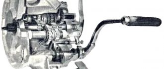
Now about the gearbox . Its defects are most often the result of poor initial assembly (if we are talking about a new motorcycle) or mistakes made by the owner during the repair process. Without stopping at disassembling the box (usually it does not cause difficulties), let's talk about how to assemble it correctly. Before starting assembly, adjust the axial clearance of the worm (follower) gear shift shaft. On an IZH-Jupiter type engine they do it this way.
Place the backing washer on the end of the hole in the right half of the crankcase and insert the worm shaft with the retainer slots facing up. Place a rigid metal ruler across the crankcase half and use a caliper depth gauge to measure how much the supporting surface of the shaft protrudes above the crankcase parting plane. Also measure on the left half of the crankcase the distance between the supporting surface of the shaft seat and the parting plane: the difference between the first and second dimensions will give the axial clearance of the worm shaft.
If this gap turns out to be more than 0.4 mm, then you need to select washers with a thickness of 0.1-0.3 mm and then install them during assembly on the end of the shaft from the side of the grooves for the retainer so that the axial gap is ultimately equal to 0, 1—0.4 mm. After completing the adjustment, remove the worm shaft and support washer.
On an IZH-Planet engine, these operations look somewhat different. Place adjusting washers, pre-lubricated with Litol, onto the left end of the follower shaft, remove the lock and install the shaft into the hole in the left half of the crankcase until it stops. Place the thrust washer on the right end of the shaft and place the gearbox cover gasket in place.
Having previously tightened the crankcase halves with three or four screws, install a metal ruler on the rib so that it rests on the parting plane and touches the shaft.
In this position, there should be a gap of 0.1-0.4 mm between the ruler and the thrust washer. It can be adjusted by installing washers on the left end of the shaft.
Assembly of the box begins with the installation of the secondary shaft in the right half of the crankcase. First, install the support and retaining rings into the crankcase hole and press the outer ring of the roller bearing until it stops against the oil seal, after which it is recommended to core the crankcase at three or four points along the outer ring of the bearing.
To prevent the rollers from falling apart, fill the groove of the secondary shaft with “Litol-24” and after that, trying not to damage the working edges of the oil seal, install the shaft into the crankcase (or its cover - if we are talking about the IZH-P model), put the sprocket in place and secure its nut.
Further assembly of the box is carried out on the right half of the crankcase, when the gear shift mechanism has already been assembled on it.
Without dwelling on the sequence of assembly operations, we would like to draw attention to one circumstance. On a fully assembled box, the gap between the secondary shaft and the thrust washer should be within 0.4-0.6 mm. If this gap is less than 0.4, you need to hammer the input shaft through a copper drift to the left. If it is more than 0.6 mm, the left input shaft bearing should be pressed inside the crankcase, and the free space between it and the locking plate should be filled with thin washers (their outer diameter is 47 mm, internal diameter is 38 mm).
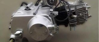
Tuning the IZH Jupiter engine
Before you start, you need to decide how much power you would like to give to your engine. If you are quite satisfied with the average power, then you will need a ZiD-200 resonator. But if you want to make the IZH Jupiter 5 motorcycle fast and powerful, start tuning the engine by installing a resistor from the SMB-5 “motoblock”.
Replacing the air filter plays a big role in engine modification. The better the air is cleaned, the more horses the engine will be able to produce. After all, the degree of engine overheating depends on the amount of incoming air. It is best to use imported air filters. They provide improved cleaning and longer service life.
Next you should work hard on the injection system. An excellent option is to install a “Planet” carburetor with a diffuser diameter of 0.32 cm. Two carburetors will provide much greater acceleration and good dynamics. We take the flanges securing the cylinder from the standard tube, grind out the aluminum studs, and cut off the flange from the carburetor from the inlet tube from the Planet.
We grind the ends of the cylinder heads on a machine, and press the cylinders themselves. The maximum permissible volume of PIC is 18 cubic meters. see Install factory copper layers under the cylinder heads. And we adjust the ignition advance angle to increase compression.
We use the second flange from the old carburetor. Then we weld the parts using “cold” welding. And finally, we modify the assembly to be compatible with the inlet channels. all the cracks with epoxy liquid . Voskhod carburetors will provide uniform traction. In this simple way, you can add not only a couple of additional horses to your pet, but also provide more lively dynamics that give a good riding experience. The motorcycle is very reliable for everyday use, and if you take good care of it, breakdowns will occur very rarely.
How did the motorcycle turn out the way it is?
The metal is sanded and coated with clear acrylic varnish. Selected color combinations and everything glossy are still boring from fiddling with computer programs. I wanted something like the so-called post-apocalyptic industrial theme. Here, for example, from the Detroit Bros workshop:
In general, I decided to assemble the Jupiter without the side borders and so that it would all shine with the steel from which it is made.
I bought a kilogram package of car varnish, it turned out to be acrylic, from Vika (about 500 rubles). I also bought thinner for acrylic paints and varnishes, also from Vika (a couple of jars for 90 rubles each), but later the hardener ran out faster than the thinner (a small jar of hardener was included with a jar of varnish). It seems that the domestic solvent R-12 is friendly with any acrylic paints and varnishes, but I have not checked.
I planned to paint with a purchased touch-up airbrush from MATRIX - with a simple round nozzle, a 0.2-liter aluminum tank, designed specifically for regular paint (not for all sorts of filling primers, which require a large diameter nozzle, greater pressure and, accordingly, greater air flow), produces spot from 5 mm to 4-5 centimeters, economically consumes paint.
I bought this touch-up airbrush for 690 rubles. And for 200 rubles a filter drier is small for him, for another 50 rubles for a set of two flanges (for a thin oxygen hose) and two nuts for a bayonet connection of such a flange to the airbrush.
On occasion, I got the compressor quite inexpensively, homemade, from a compressor from a refrigerator, a small receiver, a pressure gauge on the receiver itself, and an oxygen reducer with a thin oxygen hose. I've already modified it a little:
And also modified:
Such a compressor will not handle spray guns with high air consumption, but my touch-up airbrush works, and a small airbrush will work even more so. Although you can try a small spray gun with an LVLP spray system (originally made to work at low pressure and air flow) from IWATA, for example (I saw it on the Internet for 2300 rubles). But the compressor works no louder than a refrigerator. Otherwise, I would buy a compressor from my next salary (this is approximately 5,000 - 7,000 rubles).
Motorcycle Features
According to industry norm, the motorcycle had an alphanumeric index:
- IZH 7.107-010 – basic model;
- IZH 7.107-020 was already equipped with a new lubrication system and improved front axle suspension. In addition, the wiring diagram of the IZH Planet 5 motorcycle had a contactless ignition system, independent of the battery;
- IZH 7.107-030 was equipped with a spring-hydraulic shock absorber and a redesigned rear wheel brake drive;
- IZH 7.107-040 was produced with modified kinematics and a modified front wheel brake. The wiring diagram on IZH Planet 5 remained contactless until 2008.
How to lengthen a fork in the Urals?
The steering fork is not only one of the most important design elements, but also an integral part of the overall style of the motorcycle. Not everyone likes its factory parameters, so lengthening and changing the angle of inclination of this part is far from uncommon.
One of the main reasons for performing this procedure is the owner’s desire to turn his road-spec unit into a chopper (a type of motorcycle with a low seat, an extended frame and front forks). Before lengthening the fork in the Urals, you should decide on the required length, which, according to the recommendations of experts, should not exceed the factory one by more than 15 cm.
To increase the length of the fork, a special insert machined from a steel rod is usually used. The part is a cylindrical blank. Its conical part is equipped with a thread for a plug and is intended for installation in the upper traverse. The other side of the insert has a threaded connector for the fork stem and threads similar to those on the plug.
The parameters of the extension must be similar to the parameters of the standard Ural fork ( diameter 36 mm and identical thread pitch on the nut screwed into the fork). The workpiece must be solid-body, have a hole and thread for the fork spring rod. BzYU In the case of self-manufacturing of the insert, the following actions are carried out:
- Thread cutting in the lower part of the plug-in module with a length and pitch identical to the oil filler plug in the fork.
- Drilling a blind hole with similar thread parameters.
- Drilling a through axial oil filler hole (8-10 mm).
- Filling 0.3 m3 of liquid (for example, a mixture of MGP-10 with motor oil in a 1:1 ratio)
Final actions
You should put rubber caps on the armor wires, and insert the latter into the candlesticks or coil above. If you skip this step, the motorcycle will stall when riding in rainy weather, as moisture will get into the battery.
By inserting spark plugs into the tip, it will be possible to maintain excellent contact between the battery and the volume of the vehicle. Now you will need a pre-purchased set of wires. The switch, coil and hall sensor are connected by wiring. She needs to be isolated. Of the entire mass, only a common plus is required.
Maintenance
The owner can independently perform some maintenance procedures:
The need to inspect and adjust the wiring arises if:
Self-check of the Planet 5 motorcycle generator in case of loss of charge
The cause of loss of charge in the IZH Planet 5 battery is most often a breakdown of the generator.
To check it yourself you need:
Step-by-step instruction
The following steps must be followed:
The presence of a short circuit in the 3rd stage or a discrepancy in the indicators in the 4th will indicate problems with the generator.
Photo gallery: stages of checking the IZH Planet 5 generator in case of loss of charge in pictures
How to correctly set the gap between the contacts of the breaker?
In order to set the gap between the breaker contacts, you will need:
Next, you need to follow the steps sequentially:
Photo gallery: adjusting the gap between the breaker contacts
Troubleshooting the audio signal and improving signal quality
Poor sound signal quality is mainly caused by improper adjustment.
The following tools will be needed for setup:
Step-by-step instruction
To adjust, do the following:
Electrical circuits of domestic motorcycles IZH Jupiter-5, Planet, IZH Junker, IZH49. To enlarge the diagram, click on it. You can also download for free and via a direct link an archive with circuit diagrams.
Electrical circuits of the ignition systems of the IZH Jupiter 5 motorcycle
1 - parking light lamp - A 12-4; 2 - high beam - low beam headlight - A 12-45:40; 3 - indicator lamp for generator operation - A 12-1; 4, 5 — speedometer scale illumination lamps — AMN 12-3; 6, 16, 17, 20, 23, 30 — lamps for the direction indicators of the motorcycle and side trailer; 7 - combination switch (right switch); 8 — brake light switch for the front wheel brake; 9 - breaker; 10 — spark plug; 11 — ignition coil; 12 - generator; 13 — rectifier-voltage regulator BPV14-10; 14 — brake light switch for the wheel brake; 15, 19 — side trailer clearance lamps — A 12-5; 18 — brake light lamp for side trailer — A 12-21-3; 21 — motorcycle brake light lamp — A 12-21-3; 22 — motorcycle rear marker lamp — A 12-5; 24 - battery; 25 - fuse; 26 — neutral lamp switch; 27 — ignition switch; 28 — sound signal; 29 — alarm switch (left switch); 31 — turn signal switch; 32 - high beam headlight control lamp - A 12-1; 32 — control lamp “neutral” — A 12-1; 33 - control lamp for direction indicator lights - AMN 12-3; Symbols on the BPV14-10 block (items 12,13): XI - “-” excitation windings; X2 - “-” battery (“ground”); ХЗ - “+” output to the control lamp; X4, X5, X7 - phases of the stator winding of the generator; X8 - “+” of the battery.
How to lengthen the fork on Izha?
In Izha, as in the Urals, if possible, it is better to use a ready-made insert, the description of which is indicated above. In order to extend the fork on something else if there is none, you will need two frames (upper and lower parts) and two pipes that are inserted for reinforcement. The top frame duplex tubes are cut to be as close to the steering column as possible, but no further than the bend. With the pipes of the second frame, the opposite is true - cutting is done as close as possible to the lower bend.
The pipes are inserted into each other and scalded, after which the joints are ground off using a grinding flap wheel on a grinder.
Required Parts
In order for the ignition system to work correctly, a number of auxiliary parts are required. They are listed below:
Modulator
The most difficult stage is the production of the modulator. It is important to maintain the required shape. The more accurately the required dimensions are observed, the lower the likelihood of problems occurring after the system is implemented, that is, there will be no need to adjust it with a file. The ignition timing must match on any cylinder used.
The bolt hole must be located in the middle. Otherwise, the engine operation will not be synchronized. It is also recommended to check the integrity of the crankshaft bearings. If you find defects, you should immediately replace it.
The contact ignition is not able to work normally if the bearings are damaged. The thickness of the part should not exceed one and a half millimeters. If it is thin, it will not be possible to avoid deformation, and if it is thick, it will come into contact with the surface of the hall sensor housing.
To create the plate, it is allowed to use any material except steel. Aluminum and others should not be used as they are not magnetic. The drawing that must be followed can be found in the public domain. The presented diagram will be useful to those people who decide to modernize the vehicle ignition device. Below are methods for installing electrical ignition devices in Jupiter.
It must be turned by a professional turner. He will make a simple disk and draw on it the markings of elementary distances between the corners. Then, in accordance with it, you will cut out the necessary sectors at home. The cost of the modulator is seventy rubles.
It is not advisable to use an ordinary plate, since its width is less than twelve millimeters. This will not be enough to fully accumulate the energy resource in the coil. Of course, it can be installed, but achieving four thousand revolutions per minute will become impossible.