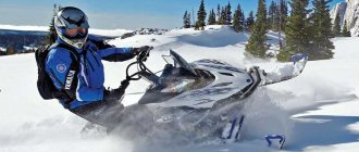
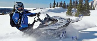
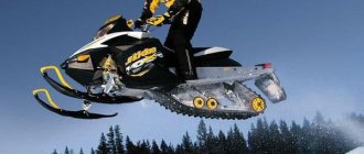
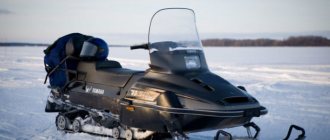
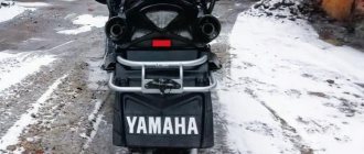
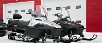
Not all equipment is able to function effectively in Russian winter conditions. And if operation is needed in Siberian regions, then only a few vehicles remain that can operate in such a climate. One such example is the famous Yamaha Biking 540 snowmobile. This Japanese snowmobile has been firmly established on the market since 1988, having undergone only minor changes.
We will begin the description of the Yamaha Viking 540 snowmobile with the fourth model, since there is no point in considering earlier options. But first, let's go a little deeper into history.
Snowmobile history
The Yamaha Viking 540 was first released in 1988. It immediately gained fame as an indestructible vehicle, ideal for fishing, hunting and working in northern conditions. In 1994, a minor redesign was made to the front end and seat. The second generation lasted on the market until 1998. The third generation, released in 2001, received new skis and a track. The fourth generation Yamaha Viking 540 was launched in 2012. It did not receive anything significantly new, except for improved skis. Tough Pro appeared in 2013? light version of the snowmobile. [ads-pc-1]
Yamaha Viking 540 Snowmobile Assembly Manual
Yamaha Viking 540 snowmobile assembly manual
Content
Location of assembly units Unpacking
Assembly
Front headlight assembly + reverse buzzer assembly Fairing Windshield Handlebar assembly Control panel Travel switch Skis Front bumper Rear bumper Rear backrest + auxiliary arms
Location of snowmobile components in the package:
A - vinyl bag B - cardboard box C - cardboard box D - cardboard box E - cardboard box F - rear bumper G - windshield H - travel switch assembly I - front bumper
——
A - vinyl bag
| 1.Keys; 2.Top holder; 3.Bottom holder; 4.Bolts |
B - cardboard box
| 1. Skis | 2.Plastic bags |
| 18.Manual | 19. Inventory |
| 3. Boxing | 4.Keys | 6.Keys | 10.Keys |
| 8.Screwdriver | 9. Handle | 7. Heads | 7. Heads |
| 11. Keys | 12. Insert | 13. Severstal |
| 14. Plate 15. Battery. dipstick | 17. Strip |
| 16. Limiter | 20. Eyelet | 21. Travel switch housing |
| C - cardboard box 1.Front headlight assembly | D - cardboard box 1. Overlay |
| F - rear bumper | E - cardboard box 1. Backrest |
| 2.Handles | 3. Rear buzzer assembly | 4. Steering wheel cover |
| 7. Bumper covers | 4. Entrance panel | 5. Bumper protector |
N - under the seat
| 1.Lever assembly; 2.Hex bolts; 3. Rear buzzer assembly; 4.Nuts |
| G- Windshield | 3. I - Front bumper |
Removing the protective frame:
1. Remove the protective cover “1”
2. Unscrew the bolts “2” and remove the top of the protective frame “3”
3. Unscrew the bolts “4” and remove the sides of the protective frame.4. Remove the cardboard box.
5. Unscrew the protective hooks “5” and bolts “6” (on both sides)
6. Unscrew the hooks "7" (on both sides)
Installation:
Front headlight assembly + reverse buzzer assembly
LIST OF ASSEMBLY UNITS
| № | Name | Qty. | Location | Note |
| 1 | Rear buzzer | 1 | Cardboard box "E" | |
| 2 | Bolt and nut | 1+1 | Complete with buzzer | |
| 3 | Headlight assembly | 1 | Cardboard box "C" | |
| 4 | Screw | 4 | Polyethyl bag. "5" | М5х0.8е=16mm(0.63in) |
| 5 | Washer | 4 | Polyethyl bag. "5" | D=14mm(0.5in)d=5.5mm(0.21in) |
| 6 | screw | 4 | Polyethyl bag. "5" | M5x0.8 |
| 7 | Clamp | 1 | Polyethyl bag. "5" | |
| 8 | Washer | 3 | Polyethyl bag. "5" | D=18mm(0.7in)d=6mm(0.24in) |
| 9 | screw | 4 | Polyethyl bag. "5" | M6x1.0 |
Install: 1. Reverse buzzer “1” into the niche using a bolt and nut “2”. 2. Front headlight assembly “3” into the niche using clamp “7”, using screw “4”, washers “5”, “8” and plas (M5), “9” (M6).
Cowl
LIST OF ASSEMBLY UNITS
| № | Name | Qty. | Location | Note |
| 1 | Fairing buzzer | 1 | Cardboard box "D" | |
| 2 | Bolt | 4 | Polyethyl bag. "5" | M6x1.0 e=20mm(0.79in) |
| 3 | Washer | 4 | Polyethyl bag. "5" | D=18mm(0.7in)d=6mm(0.24in) |
| 4 | screw | 4 | Polyethyl bag. "5" | М5х0.8е=16mm(0.63in) |
Install: 1. Install the fairing into the niche using stoppers “5”, using bolts “2”, plates and washers “3”. Install wire clamp A. 3. Connect the speedometer cable B and the speedometer C. the headlight connector D. Connect the reverse buzzer connector E.
Windshield assembly
LIST OF ASSEMBLY UNITS
| № | Name | Qty. | Location | Note |
| 1 | Windshield | 1 | On the seat | |
| 2 | Screw | 4 | Polyethyl bag. "4" | M5x0.8 e=12mm(0.47in) |
| 3 | Washer | 4 | Polyethyl bag. "4" | D=18mm(0.7in)d=5mm(0.2in) |
| 4 | screw | 4 | Polyethyl bag. "4" | M5 |
Steering wheel assembly
LIST OF ASSEMBLY UNITS
| № | Name | Qty. | Location | Note |
| 1 | Steering wheel | 1 | On the engine | |
| 2 | Steering wheel holders top | 2 | Polyethyl bag. "A" | |
| 3 | Steering wheel holders bottom | 1 | Polyethyl bag. "A" | |
| 4 | Bolt with Grover | 4 | Polyethyl bag. "A" | М8х1.25 =35mm(1.38in) |
| 5 | Steering wheel cover top | 1 | Cardboard box "E" | |
| 6 | Steering wheel cover bottom | 1 | Cardboard box "E" | |
| 7 | Clamp | 1 | Polyethyl bag. "1" | |
| 8 | Screw with washer | 2 | Polyethyl bag. "1" | M5x1.0 e=30mm(1.18in) |
| 9 | Screw | 1 | Polyethyl bag. "1" | M5x1.0 e=8mm(0.31in) |
| 10 | Washer Grover | 1 | Polyethyl bag. "1" | |
| 11 | Washer | 1 | Polyethyl bag. "1" |
Install: 1. Secure the steering column 1 with the upper 2 and lower 3 steering wheel holders, using bolts and Grover washers. Warning: • Temporarily tighten the bolts in the steering column holders.
——
• The upper steering column holder must be installed in accordance with the mark “A” forward . 2. Tighten the steering column holder bolts 4 alternately, maintaining approximately equal force on each side of the steering column.
——
ATTENTION:
•Check that the upper steering column mounts are installed with the “A” mark facing forward.
3. Clamp the throttle cable and wiring harness using clamp 7.
4. Install the front steering wheel cover 5 on the steering column holder using screws 8 and the lower steering wheel cover 6 using bolts 9, washers 10 and washers 11.
Warning: • Make sure that the hook C is latched onto the steering column D . • Make sure that the hook E is latched onto the front handlebar cover F .
Control Panel
LIST OF ASSEMBLY UNITS
| № | Name | Qty. | Location | Note |
| 1 | Panel controlled | 1 | Cardboard box "E" | |
| 2 | Eyelet | 1 | Polyethyl bag. "6" | |
| 3 | Plate | 1 | Polyethyl bag. "6" | |
| 4 | Rivet | 4 | Polyethyl bag. "6" | |
| 5 | Clamping screw | 2 | Polyethyl bag. "6" | M5x0.8 e=16mm(0.63in) |
| 6 | Washer | 4 | Polyethyl bag. "6" | D=15mm(0.6in)d=5mm(0.2in) |
| 7 | U-nut | 2 | Polyethyl bag. "6" | M5 |
Install: 1. Install control panel 1 in the hood niche using bolts 5, washers 6, nuts 7. 2. Install A inside B. Install C inside D. 3. Install grommet 2 inside the control panel using rivets 4 and washers 3.
Travel switch
LIST OF ASSEMBLY UNITS
| № | Name | Qty. | Location | Note |
| 1 | Lever assembly | 1 | Under the seat | |
| 2 | Bolt | 2 | Polyethyl bag. "6" | M6x1.0 e=25mm(0.98in) |
| 3 | Washer | 2 | Polyethyl bag. "6" | D=11.5mm(0.45in)d=6.4mm(0.25in) |
| 4 | Bolt | 1 | Under the seat | M6x1.0 e=25mm(0.98in) |
| 5 | Washer | 1 | Under the seat | D=11.5mm(0.45in)d=6.4mm(0.25in) |
| 6 | screw | 1 | Under the seat | M6 |
| 7 | Lever housing | 1 | Cardboard box "B" | |
| 8 | Screw with washer | 2 | Polyethyl bag. "6" |
Install: 1. Install travel switch 1 into the niche using special bolts 2.4 and washers 3.5, then install shift lever 9 using nut 6. 2. Secure switch housing 7 using screws 8.
Skis
LIST OF ASSEMBLY UNITS
| № | Name | Qty. | Location | Note |
| 1 | Skis assembled | 2 | Cardboard box "B" | |
| 2 | Stopper | 2 | Polyethyl bag. "2" | |
| 3 | Bolt | 2 | Polyethyl bag. "2" | M10x1.25 e=102mm(4.02in) |
| 4 | Washer | 4 | Polyethyl bag. "2" | d=10mm(0.39in) |
| 5 | screw | 2 | Polyethyl bag. "2" | M10 |
| 6 | Cotter pin | 2 | Polyethyl bag. "2" | |
| 7 | Collar | 2 | Ski bracket |
Install: 1. It is necessary to lubricate bolts 3 and collars 7. 2. Install stoppers 2 in the raised position, as shown in the diagram.
——
3. Secure skis 1 to the lower suspension bracket using bolt 3, washers 4, nuts 5, collar 7 and cotter pin 6.
——
Front bumper assembly
LIST OF ASSEMBLY UNITS
| № | Name | Qty. | Location | Note |
| 1 | Front bumper L | 1 | Lower part of the cage | |
| 2 | Front bumper R | 1 | Lower part of the cage | |
| 3 | Bumper rubber bands | 2 | Cardboard box "E" | |
| 4 | Front protector | 1 | Cardboard box "E" | |
| 5 | Side protector. L | 1 | Cardboard box "E" | |
| 6 | Side protector. R | 1 | Cardboard box "E" | |
| 7 | Part-timer | 1 | Cardboard box "B" | |
| 8 | Insert | 1 | Cardboard box "B" | |
| 9 | Plate | 1 | Cardboard box "B" | |
| 10 | Limiter L | 1 | Cardboard box "B" | |
| 11 | Limiter R | 1 | Cardboard box "B" | |
| 12 | Bolt | 8 | Polyethic bag "3-1" | M8x1.25 e=14.0mm(0.55in) |
| 13 | Screw | 10 | Polyethic bag "3-1" | M8x1.25 e=20.0mm(0.79in) |
| 14 | Washer | 2 | Polyethic bag "3-1" | D=18mm(0.71in)d=8.5mm(0.33in) |
| 15 | screw | 2 | Polyethic bag "3-1" | |
| 16 | Rivet | 2 | Polyethic bag "3-1" | |
| 17 | Rivet | 4 | Polyethic bag "3-1" |
Install: 1. Connect the front bumper (left 1 and right 2 parts) using connector 8, insert 7 and bolts 12.
——
2. Attach the front protector 4 to the front bumper using plate 9 and rivets 17.
——
3. Install limiters 10 on the transom using bolts 12 on both sides. Warning: Tighten bolt 12 Make sure that the stops are installed at mark A downwards as shown in the figure. 4.Install the front bumper onto the transom using special bolts 13, washers 14 and nuts 15. Warning: Tighten bolt 13 Make sure that part B is installed on the right, as shown in the figure. 5. Tighten bolts 12 and 13 completely.
——
6.Install the side protectors 5 on the front bumper using rivets 16,17. (At both sides).
——
7. Install bumper rubber bands 3 on the front bumper A (on both sides).
——
Rear bumper
LIST OF ASSEMBLY UNITS
| № | Name | Qty. | Location | Note |
| 1 | Rear bumper | 1 | Seat space | |
| 2 | Bolt | 4 | Polyethic bag "3-2" | M8x1.25 e=14mm(0.55in) |
| 3 | Spring washer | 4 | Polyethic bag "3-2" | D=15mm(0.6in)d=8mm(0.31in) |
| 4 | Washer | 4 | Polyethic bag "3-2" | D=18mm(0.6in)d=8mm(0.31in) |
| 5 | screw | 4 | Polyethic bag "3-2" | M8x1.25 |
| 6 | Bolt | 6 | Polyethic bag "3-4" | M8x1.25 e=20.0mm(0.79in) |
| 7 | Sleeve | 2 | Polyethic bag "3-2" | |
| 8 | Towbar | 1 | Polyethic bag "3-4" | |
| 9 | Bolt+nut | 4+4 | Polyethic bag "3-4" | |
| 10 | Cotter pin | 1 | Polyethic bag "3-4" |
Install: 1. Secure the rear bumper 1 to the transom using bolts 2, spring washers (grower) 3, washers 4, nuts 5 and bolts 6.
——
2. Insert the rear light A into the rear bumper niche and secure it using sleeve 7. Connect the electrical connector of the wires to the rear light.
3. Secure the tail light using the steel clip C to the rear bumper.
4. Install the rear towbar (towbar) on the rear bumper using bolts + nuts.
Backrest + auxiliary handles
LIST OF ASSEMBLY UNITS
| № | Name | Qty. | Location | Note |
| 1 | Backrest | 1 | Cardboard box "E" | |
| 2 | Bolt | 4 | Polyethic bag "3-3" | M6x1.0 e=16mm(0.63in) |
| 3 | Aux handle R | 1 | Cardboard box "E" | |
| 4 | Aux handle L | 1 | Cardboard box "E" | |
| 5 | Special washer R | 1 | Polyethic bag "3-3" | |
| 6 | Special washer L | 1 | Polyethic bag "3-3" | |
| 7 | Bolt | 6 | Polyethic bag "3-3" | M8x1.25 e=40mm(1.57in) |
| 8 | screw | 6 | Polyethic bag "3-3" | M8 |
Install: 1. Secure the rear backrest 1 to the rear bumper using bolts 2.
——
2. Install auxiliary handles 3 on the rear bumper using bolts 7, special washers 5 and nuts 8. (On both sides of the snowmobile).
In our store you can buy snowmobiles Yamaha Viking 540 III and Yamaha Viking 540 III Limited as well as new models Yamaha Viking 540 IV and Yamaha Viking 540 IV Limited
The lineup
At the moment, the Yamaha Viking 540 is available in five different versions:
- Tough Pro 15;
- Limited 15;
- Limited 16;
- 15;
- 16.
Especially in this series I would like to note the Limited and Tough Pro models. The difference between the first one is an exclusive white paint job, wide skis, an improved track and, which is very useful when towing,? there are rear view mirrors. It also has a tachometer. This model is designed primarily for the transportation of goods.
The Tough Pro model is specially designed for the harsh winter conditions of Russia. Roughly speaking, this option? this is the same Yamaha Viking 540, from which everything unnecessary has been cut off. And its price is significantly lower than the entire line; only children's models are cheaper than it. Another distinctive feature is that it is refueled not with simple fuel, but with a mixture of gasoline and oil. So, according to the Japanese, the engine is easier to start.
Setting up the carburetor Yamaha Viking 540
After installing the carburetor, it is adjusted. Basically, it consists of adjusting the idle speed and the fuel level in the float chamber. Also, manipulations with the carburetor should be performed only after you are convinced of the serviceability of other components.
To do this you need:
- Unscrew the spark plugs and make sure they are in good condition. If they are flooded or have heavy carbon deposits, the part must be replaced.
- Set the free play of the throttle valve drive. The working play should be at the level of 1 - 2 mm.
- Clean the air filter. The amount of air supplied depends on the condition of the element. Do not adjust idle speed with a clogged filter.
The idle speed is adjusted using two screws - one is responsible for quality, and the second for quantity. Initially, all adjustments are made on a cold engine. In the warmed-up state, the final calibration is performed. Quality screw (yellow, made of bronze). To adjust it, you need to tighten it completely and then unscrew it exactly 1.25 turns. Next, you need to warm up the motor and use the quantity screw (white, plastic) to set the minimum number of revolutions at which the motor runs without interruption (usually 900 - 950 rpm).
Important! Adjusting the idle speed of the Yamaha Viking 540 snowmobile, after running in or for other operating conditions (driving in the mountains or in severe frost), is performed purely individually. There is no universal screw position for all conditions!
Note. The idle speed setting is only relevant up to ¼ throttle lift. Therefore, to reduce fuel consumption it is necessary to select less efficient jets. But this must be done extremely carefully, since a strong reduction in the cross-section is fraught with depletion of the mixture and, as a result, frequent overheating of the power unit.
Specifications
Since this snowmobile is positioned as a utilitarian one, everything was given for the sake of efficiency and reliability. The technical characteristics of the Yamaha Viking 540 are as follows:
- engine ? two-cylinder, two-stroke with a displacement of 535 cc. CM air-cooled;
- transmission? CVT with high and low gears, reverse gear;
- brakes? mechanical, disk;
- suspension travel? 150 mm front and 385 mm rear;
- dimensions? 1355 mm height, 3055 mm length, 1190 mm width;
- tank capacity? 31 l;
- headlights? halogen, power 60 watts.
There are no differences among the models in terms of technical characteristics. [ads-pc-2]
Owner reviews
The Yamaha Viking 540 4 snowmobile, according to owner reviews, deserves a lot of attention, like most other Japanese equipment:
- The reliable two-stroke 535 cc engine works like clockwork, the main thing is that it is serviced on time. Fuel consumption, however, is slightly higher than four-stroke engines, even more cubic capacity. Low gearing allows you to transport fairly heavy loads, in particular 300 kilograms. The rear suspension provides a smooth ride, just like the front one.
- The trunk is spacious. The fuel tank is not enough, as it is designed for only 31 liters of gasoline. Because of this, reinforcement is required - an additional canister.
- This snowmobile is suitable as a workhorse and assistant.
- At sub-zero temperatures it starts quite easily.
Of the minuses:
- Sometimes there are problems with spark plugs. During the entire period of operation, the owners reported that they only managed to reach a speed of 100 km/h on the snowmobile.
- Fuel consumption reaches decent values: about twenty liters of gasoline per hundred kilometers.
Operation in winter conditions
The Yamaha Viking snowmobile is specially designed for work and recreation in harsh winter conditions. It holds a straight line perfectly at cruising speed and handles road unevenness well. This is nothing new for touring snowmobiles, but it was hard to expect for a utilitarian line. New skis and shock absorbers (gas-filled) improved the already excellent qualities of the snowmobile, significantly eliminating yaw on uneven surfaces.
Yamaha is perfect for hunters and fishermen due to its increased cross-country ability. According to them, a snowmobile passes where a person falls waist-deep. And given the state of the snowmobile infrastructure and the availability of trails, this quality is truly outstanding.
The device also copes with the transportation of cargo and passengers with a bang. Thanks to the low seating position and confident grip, the chances of flipping over on a sharp turn are close to zero.
Malfunctions and maintainability
Most often, owners of a Yamaha Viking 540, having ridden it for more than 5,000 km, rarely encounter problems or repairs. If there is any malfunction, it occurs either due to a manufacturing defect or damage.
The most common breakdowns:
- faulty spark plugs? During operation, one of the spark plugs may fail, which greatly affects the power of the snowmobile. This can be corrected by purchasing and replacing a spark plug;
- cracks in plastic tubes? It’s no secret that plastic becomes brittle in extreme cold. Therefore, these parts are considered consumables and are replaced when worn out;
- oil hunger? a manufacturing defect that occurs quite often. If it is not detected in advance, then it will no longer be possible to start the snowmobile. Self-repair is not possible.
There are also other breakdowns, but these three above? most frequent. [ads-pc-3]
Work progress with a clogged carburetor
Important! All manipulations with the snowmobile must be performed in accordance with safety regulations. It is prohibited to perform work near an open source of fire. And to protect your hands and eyes, you need to use gloves and safety glasses.
- Initially, all adjacent surfaces and the carburetor body should be cleaned of dirt. The fuel supply system reacts very sharply to dirt, sand or debris that gets into it. Even a small grain of sand can cause a malfunction and create obstacles to the normal operation of the motor;
- Next, you should dismantle the unit. To do this, you need to disconnect the air duct and all pipes and fasteners holding the unit in place;
- The procedure for disassembling the unit and washing it is performed. Disassembly is carried out by removing the jet, then dismantling the float chamber cover and the shut-off needle. Next, the throttle valve is removed. Assembly occurs in reverse order. The unit must be washed thoroughly. To do this, you can use pure gasoline, solvent or carburetor cleaner. And to clean the channels and nozzle, it is best to use a compressor or a powerful pump with a nozzle. When cleaning the jet, do not use wire or hard needles. The fact is that the part is made of a soft alloy, which can be easily damaged by steel tools, and any damage to the surface can lead to an uncontrolled change in the operating parameters of the power unit;
- Reassembly and installation of the part on the snowmobile;
- Setup.
