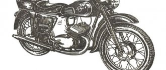
Two-wheeled motorcycle IZH Planet 5 engine, which developed only 22 hp. pp., throughout almost the entire period of its production, and from 1987 to 2008 it was considered one of the most common middle-class motorcycles among domestic buyers.
This motorcycle was developed and manufactured at the Izhevsk Machine-Building Plant (Izhmash), which is located in the capital of the Republic of Udmurtia. The main advantages that ensured the popularity of Izhevsk motorcycles, and not only in Russia, should be considered:
- Ease of use.
- Simplicity of design and maintenance.
- High overall reliability.
- Economical, repairable motors.
- Affordable prices.
In addition, Izhmash constantly sought to make changes and improvements in the design of its products, including the Izh Planet 5 motorcycle model and the Izh Planet 5 engine. At the plant itself, production was regularly modernized in order to improve quality. Thus, the assembly of power units, including the assembly of the IZH Planet 5 engine, was carried out at a specialized technological site.
Why is it worth ordering spare parts from us?
If you have already selected a suitable option, simply fill out the online form on the website, and if you can’t make a choice, call our consultants. Depending on the nature of the breakdown, we will help you decide on the purchase of rare spare parts for the Izh, Jupiter and Planet motorcycles. All specified components come with a quality guarantee. You will return your vehicle to working order with minimal investment of time and money.
The advantages of working with us are the extensive experience of our specialists in selecting components for Soviet motorcycles, the availability of even rare samples and the supply of only original and high-quality spare parts from reliable manufacturers.
MY MOTORCYCLE
The article concerns the front suspension of motorcycles IZH 7.107-015 (Planet -5-015) of newer modifications (before production closed), although the front suspension is not much different from previous models!
The front fork, as usual, consists of guide devices, elastic elements and vibration dampers. The guide devices ensure the specified movement of the wheels relative to the frame and transmit movement resistance forces and braking forces to it. Elastic elements perceive and soften impacts transmitted through the wheels to the sprung parts. Damping devices reduce the time of forced oscillations and turn! these oscillations are damped. Motorcycle front suspensions are usually made in the form of telescopic and lever forks. Telescopic forks are the most widespread - they are found on all IZh models. The licensed plug we are considering (manufactured in Japan) also belongs to this type.
It is based on two struts 17 (left) and 18 (right) of shock absorbers (Fig. 1), fixedly fixed in the upper 8 and lower 15 bridges, which are pivotally connected to the head part of the frame 12 using the steering column axis 16 and two ball bearings 11 This device allows you to rotate the fork (and with it the front wheel) relative to the frame, changing the direction of movement.
Shock absorber struts are stationary elements of guide devices. Each rack is secured in the upper and lower bridges with bolts 3 and nuts 4. In the areas between the bridges, the racks are covered with casings 1 and 2. The headlight is fixed to the brackets of the casings. The working part of a fixed pipe is called a cylinder. The outer, movable part of the fork leg slides along it, having a reservoir 22, a piston 21 with a ring 18 and a rebound spring 19. Inside the fixed pipe there are a large 8 and a small 12 spring. The tightness of the connection between the movable and stationary parts of the feather is ensured by a sealing unit, which consists of two cuffs 15, a retaining ring 17 and a protective cover 13, secured to the movable pipe with a clamp 14 and on the stationary pipe with a clamp 10. The role of the elastic element in each rack is performed by the already mentioned large and small springs with different stiffnesses: this provides the necessary nonlinearity of the suspension characteristics. In addition, compressed air is used as an elastic element in the suspension under consideration: it is pumped into each airfoil through spools 2. This is the first time this solution has been used on our motorcycles - and therefore we pay special attention to this! In order for the feathers to work equally, you need to strive to ensure that the pressure in the left and right feathers is as equal as possible. At least the difference should not exceed 0.1 kg/cm. If only one driver uses the motorcycle and his build is not very different from the average, the pressure in the feathers should be maintained at approximately 0.2 kg/cm3; if he travels with a passenger - 0.4 kg/cm3/cube; and when driving with a stroller - 0.6 kg/cm/cm. These are, of course, only approximate values. Each driver will very soon set the optimal ones for himself, based on specific conditions. The new struts are much stiffer than the old ones, since the outer diameter of the 20 cylinders has been increased to 38 mm. In addition, the suspension has an unprecedentedly long travel of up to 200 mm. And all this together allows us to say that the new front fork has significantly increased the comfort and safety of riding a motorcycle. A few words about the vibration damper. Extinguishing occurs due to the resistance forces that arise when the oil is throttled through a special valve device rolled in the lower part of the working cylinder 20, as well as due to the slow flow of the same liquid through the annular gaps between the piston 21 and the inner walls of the cylinder 20 and through the holes in the piston . Some tips regarding the operation and repair of a new fork . Practice has shown that the fork works quite stably, there are no major complaints about it. However, you need to ensure that the threaded connections are securely tightened, prevent fluid leakage, and systematically check the pressure in the pneumatic pumping system. Pay attention to the safety of protective covers. If you discover any malfunction, try to fix it as soon as possible, without delay: otherwise, a minor malfunction will certainly turn into a major one. Since motorcyclists do not have to rely on service, here are some tips on suspension maintenance.
- It is recommended to replace the hydraulic fluid for the first time after 2500 km - that is, immediately after the end of the break-in. This should not be neglected, since oil is not just a working fluid, but also a lubricant for the pen parts. If it is contaminated - and during the break-in period this process is especially active - the oil will contribute to increased wear of rubbing parts.
- The next oil change should be made after 6-7 thousand kilometers, using 300 cm3/cube of MGP-10 fluid (OST 38.1.54-74) or any other currently suitable fluid for each feather. Unfortunately, replacement can only be done when the stand is removed - this is not entirely convenient for the consumer. However, if you consider that the annual mileage of a motorcycle rarely exceeds 10 thousand km, then this operation, performed at the beginning and end of the season, will not seem so burdensome.
To remove and disassemble the rack, the following sequence of actions is recommended.
Place the motorcycle on a stand and remove the front wheel. Disconnect the front disc brake bracket, if equipped, from the moving pipe (applies to newer models). Remove the front fender together with the stamped bridge by unscrewing the bolts securing it to the bosses of the left and right movable pipes. Remove caps 3 from each stand (Fig. 2). By pressing spool valves 2, remove air from the upper cavity of the shock absorbers. Unscrew the nuts of the 4 working cylinders halfway. Loosen the coupling bolts in the lower and upper bridges, then knock the struts out of the bridges using a wooden spacer with light hammer blows on nuts 4 and remove them from the motorcycle.
To change the oil, all you have to do is unscrew nut 4 completely, remove large spring 8, bushing 11 and small spring 12 from the pipe. Be careful when you finally unscrew nut 4: springs press on it from below and it can “shoot”. Turn the rack over and drain the oil. Rinse the cylinder with clean unleaded gasoline and blow dry with compressed air. Assemble the racks and install them on the motorcycle in the reverse order. If it becomes necessary to replace seal 15, the rack should be completely disassembled. After draining the oil, remove the protective cover 13, unscrew the screw 25 and remove the cylinder 20 along with the piston 21 from the reservoir 22. By removing the retaining ring 17, you will be able to remove the cuffs 15 and replace them with new ones. To prevent oil leakage in the lower part of the rack before tightening screw 25, it is recommended to lubricate its threads with a thin layer of sealant.
I touched on only one unit of Izh motorcycles, but I don’t finish there - I will continue to publish information on configuration and repair. I hope this will help you in repair and maintenance.....
Air fork for Izh Planet 5
Content
To replace my previous publication, I present to you a new one with a more detailed description and photo. Continuing the repair of one of my motorcycles (hard workers) I got to the fork. In general, I’m starting to analyze it and this is how you see the state inside
In order for the oil seals to work in the proper order and remove oil, the working area of the feather on which the oil seals touch must be in the best possible ideal condition; any scratches (from dust, dirt) or cavities lead to inevitable leakage of oil (through the oil seal). A gas wrench for unscrewing the nuts on the feather (and not only) will help. Here is the state of the feathers BEFORE
I'm starting to polish! First, I started rubbing my hands with fine sandpaper, 800-grit for 20 minutes, I sweated and couldn’t stand it, I took the grinder in a circle with Velcro and set it to the lowest speed so as not to make holes, I put the pen on the wheel in my right hand, I rolled the grinder with my left hand like a rolling pin and + I drove the grinder to the right to the left. then the effect began. I grind carefully, no sparks should fly from under the wheel. And also ATTENTION! Don’t try to remove too deep shells, it will only make things worse. Here after the grinder
Then I glue felt onto the Velcro circle (cut from a felt boot with metal scissors) and rub it generously with GOI. Here it costs 35 rubles. There is no separate photo for the jar, there is this one
While polishing the nib, I rubbed the felt 3 times. To make it more convenient to rub on the fireplace, I heated it to the state of plasticine and took it out of the jar, then it hardens again and everything is GOOD!
I pointed the mirror now to slightly modify the cylinder itself, or rather, install the springs on the rebound, that is, so that the fork does not knock at the exit. Again a gas key and a 12 key
Last year I disassembled another fork and installed springs, but I don’t know what they were from, but here on the forum I found out that they come from the clutch. Well, when I measure it, it almost gets removed
I take it to the knife, slightly sharpen it in a circle, try it on several times, and now it fits freely. Now, in order to put it on the rod, you need to remove the cylinder nut (it does not go through the threads on the rod), I clamp the rod in a yew with a wrench, turn it to unscrew with my foot, hold the yew and pull the nut up. I assumed that it would be more difficult, but I didn’t bother too much and it was removed.
I put on the spring and assemble the cylinder
Now the seals! The glass was in this condition
I pick out the glass, or rather the old seals, away
I insert a new one and for an even fit I insert the ring that was standing, I set the head at 30, it is just the right size, then I remove the ring, insert the second one as well and it turns out that it fits a little on the first one and narrows even more, i.e. it turns out that the pen will squeeze tighter than the first one
And on top of the second oil seal I insert one ring, I save a strip of felt boots a little higher than the height that remained in the glass because... it will crimp during installation
Now I collect the pen and, in order not to mess up the direction of the seal, I put the glass through a plastic tube
And then I insert a strip of felt boots that I have stored, it can also be rubbed with goyi paste and you need to prepare it with a reserve length and cut it in place with a small addition to make the seam tighter
ATTENTION. If you push the felt with a screwdriver or something metal, try to do it so as not to nick or scratch the surface of the pen that was polished; it’s better to use some stronger piece of wood, such as birch. Now I fill in the oil at 175 g. I filled in 160. First, ATF for the automatic transmission after installation, during operation, I realized that I NEEDED EITHER to lengthen the rod by the length of the springs that I installed, OR fill in thicker oil, OR, as a last resort, cut the main springs to the same length because when the fork comes out, there is of course no knocking, but These springs can be reached easily and since I know that the fork is more than 25 years old and the wear on it is not small, I replaced the ATP oil with diesel oil and then everything became great, just really great. It works smoothly. I really like it. It’s been a while since I’ve ridden a good fork. A week has passed, no oil leaks, this is the most important thing. Well, this is also at your discretion, but on both Izhas I have it done like this. The fork casing is cut off right along the traverse and there are Voskhod corrugations in this case, complete insulation from dust and dirt. Well, I like the view better.
Engine for the fifth model.
The Izh Planet 5 engine contains the following main characteristics and indicators:
- execution type – two-stroke with one cylinder;
- working volume – 345 cubic meters. cm;
- piston diameter – 72 mm;
- power – 22.0 l. With. at 4800 crankshaft rpm;
- battery voltage – 12 volts;
- cooling option – air;
- ignition type – contactless;
- the ratio of the mixture of oil and gasoline (A 76) is 1/30.
Such engine characteristics gave it a very important feature, which was to provide high traction performance at low speeds, which is important in rural road conditions.
Izh P-5 engine design
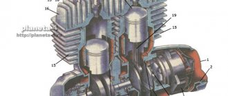
The design of the engine together with the clutch and gearbox and the general view of the engine are shown in the figure. The detailed design of components and parts is shown in catalog (detailed) drawings, and the designations of parts and components and their applicability are given in the corresponding tables.
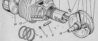
The engine cylinder consists of an aluminum jacket with cooling fins, inlet and outlet flanges for fastening the corresponding pipes, a reinforced cast-iron liner with windows, aluminum plugs that form the bypass channels, and fastening parts. The cylinder along the inner diameter of the liner has four size groups, according to which the pistons are manufactured. The new cylinder and piston are selected from the same groups. When replacing a piston, it is allowed to install it from the next group (larger diameter). An oval-barrel-shaped piston without piston rings must move in the cylinder under the pressure of its own weight, and a piston with a split skirt and piston rings must move with a force of 3-8 kg.
The aluminum alloy cylinder head has cooling fins, a spherical combustion chamber, and threaded holes for installing a spark plug and decompressor.
The piston is cast from a high-silicon, low-expansion aluminum alloy with three piston rings and grooved holes in the bosses for installing the piston pin and circlips. Pistons are used both with a split skirt and solid ones with an oval-barrel-shaped working surface.
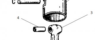
The crankshaft is designed to convert the reciprocating motion of the piston into rotational motion and consists of cast iron flywheels with pressed-in axle shafts, a crank pin, a connecting rod with a roller bearing and spacer washers. The bearing between the connecting rod and the piston pin is a bronze bushing.
The crankcase is the base on which and in which the engine parts, clutch and gearbox are assembled. The crankcase consists of several functional parts cast from aluminum alloy. In order to ensure alignment of the holes for the crankshaft bearings and the gearbox shafts, the crankcase halves and cover are processed as an assembly. Therefore, the use of crankcase parts from different engines (during repairs) is unacceptable.
Directly functionally related to the engine in the crankcase is the crank chamber, in which the crankshaft is mounted on rolling bearings. Since the crank chamber participates in the engine operating cycle as a scavenge pump, it must be sealed. This is ensured by high-quality assembly of the crankcase halves along the connection planes and the crankshaft oil seals (cuffs).
The right oil seal protects the crank chamber from the penetration of air from the cavity of the generator, and the left one protects air and oil from the cavity of the motor transmission and gearbox. The output end of the gearbox secondary shaft is also sealed with a rubber seal. The remaining holes in the gearbox shafts are plugged with special plugs and sealant. The crankcase halves, as well as the crankcase cover, are secured against mutual displacement by control bushings.
The transmission (power train) of a motorcycle ensures the transmission of torque from the engine crankshaft to the drive wheel of the motorcycle and changes it depending on road conditions and load. The transmission consists of a motor transmission, clutch, gearbox and transmission to the rear wheel.
General view of the engine and cylinder group
1 - gasket, 2 - pipe, 3 - bolt, 4 - washer, 5 - cylinder gasket, 6 - cylinder assembly, 7 - cylinder plug, 8 - gasket, 9 - gasket, 10 - screw, 11 - exhaust pipe, 12 - stud, 13 - vibration damper, 14 - cylinder head, 15 - vibration damper, 16 - cylinder head assembly with vibration damper, 17 - washer, 18 - nut, 19 - spark plug A23-1, 20 - decompressor assembly, 21 - washer , 22 — stud, 23 — carburetor, 24 — Engine assembly with carburetor and air filter, 25 — Air filter assembly
| Part designation | the name of detail | Quantity per motorcycle, pcs. | ||||
| PZ | P4 | P5 | P5-01 | |||
| 1 | 2 | 3 | 4 | 5 | 6 | 7 |
| 1 | IZhPZ. 1-3 | Pad | 1 | 1 | — | — |
| IZhP5. 1-26 | Pad | — | — | 1 | 1 | |
| 2 | IZhP4. 1-3 | Pipe branch | 1 | 1 | — | |
| IZhP5. 1-3 | Pipe branch. | — | — | 1 | — | |
| 3 | 360015-29 | Bolt M8 x1 -6gx22 | 2 | 2 | 2 | 2 |
| 4 | 252155-29 | Washer 8 | 2 | 2 | 2 | 2 |
| 5 | IZH56. 1-204-5 | Cylinder gasket | 1 | 1 | 1 | 1 |
| 6 | IZhPZ. Sat. 1-50-1 | Cylinder assembly | 1 | 1 | — | — |
| IZhP5. Sat. 1-5-2 | Cylinder assembly | — | — | 1 | — | |
| 7 | IZH56.1-260 | Cylinder plug left | 1 | 1 | 1 | 1 |
| IZH56.1-261 | Cylinder plug right | 1 | 1 | 1 | 1 | |
| 8 | IZH56.1-265 | Pad | 2 | 2 | 2 | 2 |
| 9 | IZhP5.1-25 | Pad | — | — | 1 | 1. |
| 10 | IZHV-122 | Screw M8-6ghx22 | — | — | 2 | 2 |
| 11 | IZhP5. 1-5 | Exhaust pipe | — | — | 1 | 1 |
| 12 | IZHSPI-1 | Hairpin 2M8-6gx95 | — | — | 2 | 2 |
| 13 | IZhP5. 1-37 | Vibration damper | — | — | 3 | — |
| IZhP5.1-38 | Vibration damper | — | — | 1 | — | |
| 14 | IZhP5. 1-1-1 | Cylinder head | 1 | 1 | — | — |
| 15 | IZhP5. 1-36 | Vibration damper | — | — | 2 | — |
| 16 | IZhP5. Sat. 1-28 | Cylinder head assembly with vibration damper | — | — | 1 | — |
| 17 | IZHSB-19-1 | Washer-10 | 6 | 6 | 6 | 6 |
| 18 | IZhG-103 | Nut M10-6N | 6 | 6 | 6 | 6 |
| 19 | A23-1 | Spark plug | 1 | 1 | 1 | 1 |
| 20 | IZH49. Sat. 1-27 | Decompressor assembly | 1 | 1 | 1 | 1 |
| 21 | IZHP. 1-332 | Washer | 1 | 1 | 1 | 1 |
| 22 | IZH56. 1-206-1 | Hairpin | 6 | 6 | 6 | 6 |
| 23 | K65I-1107010 | Carburetor | 1 | 1 | 1 | 1 |
| 24 | IZhP5. Sat. 1-0 | Engine complete with carburetor | — | — | 1 | — |
| IZhPZ. Sat. 1-0-3 | Engine complete with carburetor and air filter | 1 | — | — | — | |
| IZhP4. Sat. 1-0-3 | Engine complete with carburetor and air filter | — | 1 | — | — | |
| IZhP5. Sat. 1-0-3 | Engine complete with carburetor and air filter | — | — | 1 | ||
| 25 | IZhPZ. Sat. 9-0-1 | Air filter assembly | 1 | 1 | 1 | — |
Design of the Planet 5 engine with clutch and gearbox (sectional view)
1 - spark plug, 2 - cylinder head, 3 - cylinder, 4 - piston, 5 - piston ring, 6 - piston pin, 7 - crankcase, 8 - main bearing lubrication channel, 9 - roller bearing, 10 - left oil seal, 11 — left cover, 12 — motor chain, 13 — ball bearing, 14 — crankshaft sprocket, 15 — outer clutch drum, 76 — clutch disk, 17 — inner drum, 18 — pressure plate, 19 — spring, 20 — shaped nut , 21 — pusher, 22 — ball bearing, 23 — outer drum ratchet, 24 — gear shift lever, 25 — trigger lever, 26 — trigger shaft, 27 — gear shift shaft, 28 — trigger sector, 29 — spring, 30 , 31, 32, 39, 40, 42 - gearbox gears, 33 - gear shift fork, 34 - stop, 35 - gear shift shaft, 36 - gearbox cover, 37 - installation sleeve, 38 - right cover, 41 - intermediate shaft, 43 — ball bearing, 44 — roller bearing, 45 — secondary shaft, 46 — input shaft, 47 — clutch adjusting screw, 48 — worm ball, 49 — clutch worm, 50 — secondary shaft nut cap, 51 — oil seal, 52 — sprocket , 53 — generator, 54 — right oil seal, 55 — roller bearing, 56 — gasket, 57 — crankshaft, 58 — bypass channel, 59 — exhaust window, 60 — decompressor.
Crankcase
| Part designation | the name of detail | quantity per motorcycle, pcs. | ||||
| P3 | P4 | P5 | P5-01 | |||
| 1 | 2 | 3 | 4 | 5 | 6 | 7 |
| IZhPZ. S6.1-53 | Carter with details | 1 | — | — | — | |
| IZhP4.S6.1-1-2 | Carter with details | — | 1 | 1 | — | |
| 1 | IZHSB-27 | 5-fiber washer | 1 | 1 | 1 | 1 |
| 2 | Screw M6-6gX58 | 1 | 1 | 1 | 1 | |
| 3 | IZHV-117 | Screw MB-6gX58 | 5 | 5 | 5 | 5 |
| 4 | IZhPZ. S6.1-76-G | Left crankcase cover | 1 | 1 | 1 | — |
| 5 | IZH56.1-214 | Left crankcase cover gasket | 1 | 1 | 1 | 1 |
| 6 | IZH56.1-228-1 | Filler plug | 1 | 1 | 1 | — |
| 7 | IZHSB-124 | Washer 14-fiber | 1 | 1 | 1 | — |
| 8 | IZHV-25 | Screw B1.M5-6gX12 | 9 | 9 | 9 | 9 |
| 9 | IZH56.1-218-2 | Locking bar | 1 | 1 | 1 | 1 |
| 10 | IZHSB-114 | Adjusting washer | 2 | 2* | 2* | 2* |
| IZHSB-116 | Adjusting washer | 2 | 2* | 2* | 2* | |
| 11 | IZHSB-11-1 | Adjusting washer | 7 | 7* | 7* | 7* |
| IZHSB-11, | Adjusting washer | 3 | 3* | 3* | 3* | |
| 12 | IZHSB-24 | Adjusting washer | 4 | 4* | 4* | 4* |
| IZHSB-24-1 | Adjusting washer | 2 | 2* | 2* | 2* | |
| 13 | 203 | Ball bearing | 2 | 2 | 2 | 2 |
| 14 | 204 | Ball bearing | 1 | 1 | 1 | 1 |
| 15 | IZH49.1-39 | Drain plug | 1 | 1 | 1 | 1 |
| 16 | IZH49L-181 | Pad | 1 | 1 | 1 | 1 |
| 17 | IZH56.1-208-1 | Cylinder mounting stud | 4 | 4 | 4 | 4 |
| 18 | 252156-29 | Washer 10 | 4 | 4 | 4 | 4 |
| 19 | IZhG-103 | Nut M10-6N | 4 | 4 | 4 | 4 |
| 20 | IZhP4.1-41 | Breather | 1 | 1 | 1 | 1 |
| 21 | IZhP4.1-33 | Neutral contact | 1** | 1 | 1 | 1 |
| 22 | IZhP.1-209-2 | Left crankcase half | 1 | 1 | 1 | 1 |
| 23 | IZH49.1-27 | Crankcase bushing | 2 | 2 | 2 | 2 |
| 24 | IZHP. 1-210-1 | Right crankcase half | 1 | — | — | — |
| IZhP4.1-6 | Right crankcase half | — | 1 | 1 | — | |
| 25 | IZH49.1-159 | Gaskets | 1 | 1 | 1 | 1 |
| 26 | IZhP.1-213-3 | Transmission cover | 1 | 1 | 1 | — |
| 27 | IZH49.1-23 | Installation sleeve | 3 | 3 | 3 | 3 |
| 28 | IZH49.1-35 | Stub | 3 | 3 | 3 | 3 |
| 29 | IZH49.1-30 | Stub | 1 | 1 | 1 | 1 |
| 30 | IZH49.1-31 | Retaining ring | 1 | 1 | 1 | 1 |
| 31 | IZhP5.Sb.1-3 | Right cover assembly | 1 | 1 | 1 | — |
| 32 | 220086-13 | Screw M5-68HZO | 2 | 2 | 2 | 2 |
| 33 | IZhP4.1-32 | Generator cover | 1 | 1 | 1 | — |
| 31,32,33 | IZhP3. Sat.1-55 | Cover assembly • ~ | 1 | — | — | — |
| 34 | IZH49. Sat.1-28-1 | Oil seal assembly | 1 | 1 | 1 | 1 |
| 35 | IZHP.1-327 | Installation ring | 1 | 1 | 1 | 1 |
| 36 | IZHV-113 | Screw M6-6gX 30 | 2 | 2 | 2 | 2 |
| IZH49.1-23 | Installation sleeve | 3 | 3 | 3 | 3 | |
| 37 | IZHV-8 | Screw M6-6gX 37 | 3 | 3 | 3 | 3 |
| 38 | IZHV-5 | Screw M6-6gX 45 | 2 | 2 | 2 | 3 |
| 39 | IZHV-2 | Screw M6-6gX 65 | 8 | 8 | 8 | 8 |
| 40 | IZH49.1-188 | Installation sleeve | 2 | 2 | 2 | 2 |
| 41 | 252004-29 | Washer 6 | 2 | 2 | 2 | 2 |
| 42 | IZHP. 1-334 | Stub | 1 | 1 | 1 | 1 |
| 43 | IZHV-1 | Screw M6-6gX50 | 2 | 2 | 2 | 2 |
| 44 | IZHSHT-3 | Cylindrical pin | 1 | 1 | 1 | 1 |
* Largest quantity ** With modification of the crankcase (drilling and threading M12)
Transmission
The gearbox is designed to change the gear ratios of the motorcycle's power train (transmission) depending on the load, road and other driving conditions, as well as to disconnect the engine from the motorcycle's power train.
The gearbox consists of a gearbox and a gear shift mechanism.
| Part designation | the name of detail | Quantity per motorcycle, pcs. | ||||
| P3 | P4 | P5. | P5-01 | |||
| 1 | 2 | 3 | 4 | 5 | 6 | 7 |
| 1 | IZhPS. 1-40-2 | Primary shaft | — | — | 1 | 1 |
| IZhPS. 1-40-1 | Primary shaft | 1 | 1 | — | — | |
| 2 | IZhPS. 1-42-2 | 2nd gear | — | — | 1 | 1 |
| IZhPS. 1-42-1 | 2nd gear | 1 | 1 | — | — | |
| 3 | IZH49.1-41 | Thrust washer | 1 | 1 | 1 | 1 |
| 4 | IZh49.1-42 | Installation ring | 1 | 1 | 1 | 1 |
| 5 | IZhPS. 1-41-1 | 2nd and 4th gear gear | 1 | 1 | 1 | 1 |
| 6 | IZhPZ. Sat. 1-86-1 | Primary shaft assembly | — | — | 1 | 1 |
| IZhPZ. Sat. 1-80 | Primary shaft assembly | 1 | 1 | — | — | |
| 7 | IZHSB-34or | Washer | 1 | 1 | 1 | 1 |
| IZHSB-34-1 | Washer | 1 | 1 | 1 | 1 | |
| 8 | IZhP2. Sat. 1-92-1 | Secondary shaft with bearing | 1 | 1 | 1 | 1 |
| 9 | IZH56.1-282 | Secondary shaft sprocket | 1* | 1* | 1* | 1* |
| IZH49.1-128 | Secondary shaft sprocket | 1 | 1 | 1 | 1 | |
| 10 | IZH49.1-129 | Lock washer | 1 | 1 | 1 | 1 |
| 11 | IZH49.1-130 | Secondary shaft nut | 1 | 1 | 1 | 1 |
| 12 | IZhP2.1-416 | Cap • nuts of the secondary shaft | 1 | 1 | 1 | 1 |
| 13 | IZhP2:1-420 | Ring | 1 | 1 | 1 | 1 |
| 14 | IZhP4.1-56 | Intermediate shaft | 1 | 1 | 1 | 1 |
| 15 | IZhPS. 1-45-1 | 3rd gear | 1 | 1 | 1 | 1 |
| 16 | IZH49.1-48 | Installation ring | 2 | 2 | 2 | 2 |
| 17 | IZhPS. 1-44-1 | 1st and 3rd gear gear | 1 | 1 | — | — |
| IZhPS. 1-44-2 | 1st and 3rd gear gear | |||||
Reasons for repair.
Complete disassembly of the Izh Planet 5 engine during repair work is carried out if damage or breakdown of the following elements occurs:
- crankshaft;
- bearings;
- piston;
- connecting rod
Failure of these parts can occur due to engine jamming, general severe wear, which is accompanied by increased noise during operation, as well as various knocking noises in the crankcase. In addition, repair of the Izh Planet engine with its complete disassembly is carried out when the crankshaft seals are worn out.
The presence of such a breakdown is indicated by the following points: difficult starting of the internal combustion engine, loss of power, increased smoke.
At the initial stage of production of power units, the reed valve on the Izh Planet 5 had certain technological shortcomings associated with low strength. Therefore, it quickly collapsed, its elements fell inside the cylinder, which required further disassembly and, in most cases, replacement of the Izh Planet 5 piston. After a certain time, the manufacturer eliminated this defect.
If, when operating the engine, all routine and technical maintenance procedures established by the manufacturer were observed, and appropriate technological materials and fluids were used, then it was operated for a long time, while maintaining its technical parameters.
