Why is it worth ordering spare parts from us?
If you have already selected a suitable option, simply fill out the online form on the website, and if you can’t make a choice, call our consultants. Depending on the nature of the breakdown, we will help you decide on the purchase of rare spare parts for the Izh, Jupiter and Planet motorcycles. All specified components come with a quality guarantee. You will return your vehicle to working order with minimal investment of time and money.
The advantages of working with us are the extensive experience of our specialists in selecting components for Soviet motorcycles, the availability of even rare samples and the supply of only original and high-quality spare parts from reliable manufacturers.
About the advantages of a floating piston pin fit
The assembly process is the final stage of product manufacturing. The service life of the product as a whole depends on the quality of assembly. Poor assembly of even parts manufactured in compliance with all technical requirements will inevitably lead to a decrease in the service life of the unit. An example of poor-quality assembly can be: misalignment of assembled parts, reduced tension, damage to mating surfaces, which ultimately leads to increased noise and vibration during operation and reduced durability of the assembly. This article provides an overview of two methods for seating the piston pin in the piston bosses and connecting rod bushing:
1) A fit in which the pin is pressed into the bosses and rotates freely in the bushing.
2) Floating fit, in which the pin rotates freely in both the bosses and the bushing
The resource of a given connection when assembled using these methods will also be compared.
Description of the design of the unit, its service purpose, assembly features, accuracy indicators of parts
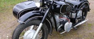
In the article, the object of consideration is the connection of the piston pin with the piston and connecting rod of the Izh Planet 5 engine. A general view of the power unit is shown in Figure 1:
Rice. 1. General view of the power unit
The Izh Planet 5 engine has the following technical characteristics:
– Engine type two-stroke single-cylinder
– Cylinder diameter, mm 72
– Piston stroke, mm 85
– Compression ratio 8.2–8.7
– Displacement: 346 cm3
– Maximum engine power, hp. 22 at 4850 rpm
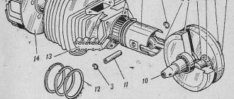
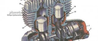
The piston pin serves to connect the piston to the connecting rod. This connection is shown in Figure 2:
Rice. 2. Connection of the piston to the connecting rod
The piston pin (1) is installed in the piston bosses (2) and in the bushing (4) of the upper head of the connecting rod (3). The pin is fixed in the bosses using locking rings (5). There are 3 ways to assemble this connection:
1) The pin is installed with an interference fit in the piston bosses, with a gap in the connecting rod bushing
2) The pin is installed with clearance in the piston bosses, but with interference in the connecting rod bushing
3) Floating fit, in which the pin is installed with clearance both in the piston bosses and in the connecting rod bushing
In this engine, the pin is installed with an interference fit in the piston bosses, with a gap in the bushing of the upper connecting rod head.
Assembling a pin that has an interference fit has some disadvantages. Firstly, assembly will require heating of the female part, since the use of cold pressing is highly undesirable (damage to the connecting rod is possible). Secondly, during an interference fit, the working surface of the pin wears unevenly, which leads to a decrease in the service life of the connection.
These disadvantages are eliminated by the floating pin fit, in which the pin is installed in the piston bosses and in the connecting rod bushing by hand, and there is no need to use the thermal assembly method. Also, with such a fit, the finger has the ability to rotate, while the working surface wears evenly.
Experiment
Two Izh Planet 5 engines were used in the experiment, 2 sets of spare parts produced by Izhmash OJSC were purchased - first repair pistons, piston rings, piston pins, retaining rings. Produced:
1) Boring of the cylinder with a thermal gap of 0.05 mm
2) Replacement of the bushings of the upper heads of the connecting rod, with subsequent modifications by deployment
3) Setting the gap in the piston ring lock to 0.3 mm
4) We expand the piston bosses from set 2 to ensure that the pin fits with clearance
The dimensions were measured with a micrometer and calipers and an analysis of the quality indicators of the assembled parts was carried out, which is presented in Table 1.
Table 1
Analysis of parts quality indicators
Thus, the dimensions are within the tolerance range, which allows us to judge the quality of the assembled parts.
Two engines were assembled, run-in was carried out in compliance with the manufacturer's recommendations for 2000 km, no extraneous knocks were detected.
Engine operating conditions
Motorcycles are operated under the same conditions:
– Motorcycles are used primarily on asphalt roads
– The cruising speed of motorcycles on the highway is 80–90 km/h, the engine speed is 2800–3200 rpm, in the urban cycle the speed range is 2000–2500 km/h. For the Izh Planet 5 engine, this operating mode is the most optimal in terms of service life
– Fuel consumption for both engines was 4–4.5 liters per 100 km, which shows the excellent overall technical condition of the engines
– The advance angle is set to 3.25 mm before TDC
– Engines are lubricated with a mixture of AI 92 gasoline and Lukoil 2T oil in a ratio of 1:25
– Maintenance every 5,000 km (changing gearbox oil, cleaning and adjusting the carburetor, cleaning the external surfaces of engines from dirt)
Experiment results
After 20,000 km, the engines were dismantled, followed by troubleshooting:
Engine No. 1 (pin fit with interference fit in bosses)
During operation, a slight metallic knocking sound was detected when the engine was running cold; when warmed up, the knocking noise disappeared. Allows you to indirectly judge the initial wear of the pin-bushing connection. 4 measurements were taken of the pin and bushing. The results are shown in Table 2.
table 2
| Detail | №measurements | Scatter field size | |||
| 1 | 2 | 3 | 4 | ||
| Finger | 14.856mm | 14.944mm | 14.953mm | 14.663mm | 0.088mm |
| Sleeve | 15.102mm | 15.354mm | 15.283mm | 15.424mm | 0.322mm |
Conclusions: the accuracy indicators exceed the permissible limits, the size dispersion field is quite large, which makes it possible to judge the uneven wear of parts.
Engine No. 2 (floating pin mounting)
No extraneous knocking noises were detected during operation. 4 measurements were taken of the pin, bushing and bosses. The results are shown in Table 3.
Table 3
| Detail | №measurements | Scatter field size | |||
| 1 | 2 | 3 | 4 | ||
| Finger | 15,002 | 15,002 | 15,003 | 15,001 | 0,002 |
| Sleeve | 15,01 | 15,012 | 15,011 | 15,01 | 0,002 |
| Lugs | 15,025 | 15,025 | 15,024 | 15,025 | 0,001 |
Conclusions: accuracy indicators are within the tolerance range, there is an insignificant size dispersion field.
Conclusion
Thus, analyzing the results of the experiment, the following advantages of a floating fit of the piston pin were revealed, compared to an interference fit:
– Simplicity of the assembly process
– Uniform wear of the working surface of parts
– Longer service life
Literature:
- K. P. Bykov, P. V. Grishchenko; ed. T. A. Shlenchik. Motorcycle "Izh". Operation, repair, parts catalog: repair manual. - Chernigov: PKF "Ranok", 2000. - 208 p.
- Tamarkin M. A., Davydova I. V., Tishchenko E. E. Assembly production technology. - Rostov-on-Don: Phoenix, 2007. - 270 p.
MY MOTORCYCLE
Everyone knows that: the power and “thrust” of the engine directly depend on the condition of the parts of the cylinder-piston group. You also know that the friction surfaces of these parts wear out due to dust, the use of low-quality oils, and simply from prolonged use. Since it is practically impossible to measure engine power in everyday conditions, many use an indirect indicator - maximum speed, while others measure compression in the cylinder. The second method of assessing power is more preferable, because the speed capabilities of the device may decrease, for example, due to the fact that the exhaust system is coked, the ignition control is disrupted, or the carburetor malfunctions. If the engine is really stuck, do not rush to immediately bore the cylinder to the repair size. Experienced people usually adhere to the following sequence of actions: the first time they change the rings, the second time - the rings and the piston (both times - to nominal sizes), then they change the rings again (also to nominal sizes) and only then bore the cylinder for the first repair with subsequent installation of a repair piston with rings. When to start these replacements depends mainly on the operating conditions. The first replacement of the rings may be necessary after six to seven (and up to 25 for large-capacity devices) thousand kilometers, and the piston after 15-40. The degree of wear can be assessed by disassembling the cylinder-piston group. When disassembling, you need to firmly remember two things.
First, don't drop the retaining ring into the crank chamber. To avoid this trouble, immediately cover the camera with, say, a rag.
And second, don’t bend the connecting rod when you start knocking out the pin with a hammer. It is best to use a puller. So, the piston is in your hands. Carefully remove the rings from it (use three or four shims (Fig. 1) and insert them into the top of the cylinder.
“Align” the rings with the piston - insert it into the cylinder from below and measure the gaps in the ring locks (Figure 2). If they exceed 3 mm, the rings must be replaced. Gaps in the locks of new rings should not exceed 0.2-0.4 mm.
Immediately evaluate the condition of the piston: if the gap between it and the cylinder is more than 0.3-0.4 mm, the piston requires replacement. When selecting a new piston, it is convenient to follow the “old-fashioned” method: a washed and lubricated cylinder lies on the table, and you lower the piston into it. A “good” piston should lower under its own weight for about one second. If it fails with a knock or, even worse, gets stuck “halfway,” look for another piston. Each motorcycle model has from two to four size groups of pistons; their difference in diameter can be from 0.01-0.025 mm. The group marking is usually stamped on the top of the piston and on the lower end of the cylinder. Make sure these numbers match. Pay special attention to the condition of the used piston. Inspect it for cracks and, if there are any, throw it in the trash. As a rule, cracks appear in the area of the bosses on the inner surface of the piston and in the corners of the purge ports. One way or another, cracks always form in places of increased stress concentrations (Fig. 3).
These include sharp internal corners remaining after machining the piston, or due to casting defects. Round such places with a file, a cutter and polish thoroughly. However, cracks are not the only danger that awaits the piston in its endless reciprocating movements. Piston rings can also present a surprise. Most often, it is necessary to clean the ring grooves from carbon deposits when the rings themselves lose mobility (“become stuck”). Do this with a piece of an old ring or a sharp object such as a scraper. It is highly undesirable to use needle files or hacksaw blades for cleaning: you can clean off the “meat” of the piston along with the carbon deposits. You can imagine the consequences: due to gas leakage between the ring and the piston, compression drops with all the ensuing consequences. Locking pins are installed in the same grooves. They fix the rings so that they do not rotate on the piston. If in a two-stroke engine, in the cylinder of which there are intake, exhaust and scavenge ports, the ring begins to rotate (which is what happens when the pin falls out), then at one terrible moment the joint of the ring will inevitably end up in the area of the intake (or exhaust) port. The ring tends to unclench, its ends straighten a little and enter the window. The next moment, the opposite edge of the window cuts off the ends of the ring that had protruded “free,” and the engine, with a clang and roar, spits out its fragments into the muffler. But don't look for pins on four-stroke pistons. On them, the rings are simply separated with joints in opposite directions, because there are no “dangerous” windows at all. Is the difference clear?! So, now we know that the locking pin in a two-stroke engine is a very important part. The “correct” pin orients the joint of the ring to the section of the sleeve without windows (Fig. 4)
The next object of study is the hole for the piston pin. In the grooves of this hole on each side of the piston there are retaining rings with curved antennae. The purpose of the antennae is to facilitate the installation and dismantling of retaining rings in the piston. This is the story with them: the design of such retaining rings has not taken root on sports engines - due to the danger that the tendrils will be cut by the piston pin and get into the cylinder. Therefore, on all modern highly accelerated engines, exclusively “mustless” retaining rings are used. And for the convenience of their dismantling, a special groove is provided on the piston. But whatever the shape of the retaining ring, it must be buried in the groove by at least half the diameter of the wire from which it is made. By the way, we recommend a proven method that prevents the circlips from being pushed out by the piston pin. Remove the antennae from the rings, and slightly increase the chamfers at the ends of the finger along the outer diameter (Fig. 5). Now the finger will more reliably lock the locking ring with such a chamfer.
When the engine heats up, the gap between the piston and the liner should be uniform along its entire perimeter. Therefore, the piston in a cold state has a very complex shape: conical, stepped or barrel-shaped in height, and oval in cross section. The greatest ovality is in the area of the hole for the piston pin (up to 0.03 mm). Therefore, when measuring the piston, do not be surprised that it is “wrong”. So, you have selected the piston to the cylinder, now look for a suitable pin. The diameters of fingers, like pistons and cylinders, are divided into several (up to four) size groups. Select the finger according to the factory instructions. Usually a dot is placed on the end of the finger with paint of a certain color. A mark of the same color is applied to the boss inside the piston. At room temperature, the piston pins of modern motorcycle engines generally engage the piston boss with little force. However, on older models, the fingers were pressed into the piston, for which the pistons were heated in boiling water... Again, carefully read the instructions for your motorcycle. We remind you again: when working with the locking rings, cover the crankcase with a rag. This simple operation will save you from having to shake an upside-down motor until you are blue in the face to remove a part that has fallen inside. When installing the locking rings (with or without whiskers), check that they are seated correctly: each ring should sit tightly in the groove, but scroll around the circumference when you press with an awl on one of its edges. As an anecdote, you constantly hear about “craftsmen” who install pistons “back to front.” An arrow stamped on all piston heads of domestic two-stroke engines, without exception, will help you avoid inevitable breakage of the rings - it indicates how the piston should be oriented. True, all Izh-Jupiters have an arrow pointing to the carburetor. If the arrow is missing or not visible, orient the piston according to the location of the locking pins: they should “look” at the vertical sectors of the liner without windows…….