Why is it worth ordering spare parts from us?
If you have already selected a suitable option, simply fill out the online form on the website, and if you can’t make a choice, call our consultants. Depending on the nature of the breakdown, we will help you decide on the purchase of rare spare parts for the Izh, Jupiter and Planet motorcycles. All specified components come with a quality guarantee. You will return your vehicle to working order with minimal investment of time and money.
The advantages of working with us are the extensive experience of our specialists in selecting components for Soviet motorcycles, the availability of even rare samples and the supply of only original and high-quality spare parts from reliable manufacturers.
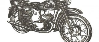
Operating principle of the IZH Jupiter 5 engine
The internal combustion engine of the Izh Jupiter 5 motorcycle consists of the following systems and mechanisms:
2. Gas distribution mechanism
. It supplies the working mixture to the combustion chamber at the required time and removes exhaust gases from it. In two-stroke engines, the role of such a device is played by the cylinder and piston.
3. Ignition system
necessary to ignite the compressed mixture in the engine cylinder.
4. Supply system
prepares the working mixture of fuel and air required for engine operation.
5. Lubrication
. In two-stroke engines IZH-P3, IZH-Yu3 there is no separate lubrication system. Oil is supplied to the cylinder at the same time as fuel.
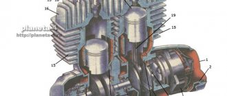
The main unit of the internal combustion engine is the CRANK MECHANISM (Fig. 10, 12, 13), consisting of a crankshaft 15, connecting rod 4, piston 2. The crankshaft in the engine crankcase is mounted on bearings. The lower head of the connecting rod rests through a roller ball bearing 7 on the crank pin b of the crankshaft. The crankshaft performs a rotational movement. The upper head of the connecting rod is pivotally connected to the piston through piston pin 11. It reciprocates simultaneously with the piston.
The gas pressure through the piston pin of the progressively moving piston passes to the connecting rod, starting from there to the crank pin of the crankshaft. Directly under the influence of this force, the crankshaft begins to rotate. In this way, the internal combustion engine processes the thermal energy of the fuel due to movement.
The motorcycle is equipped with a two-stroke engine. The role of the gas distribution mechanism (GRM) in it falls on the piston. The cylinder shell contains special windows connected to the carburetor, muffler and crankcase. Gas distribution is carried out using the movement of the piston, which, moving inside the cylinder, sequentially closes/opens these windows.
Top Dead Center (TDC)
, the position at which the piston is at its maximum distance during rotation from the crankshaft, respectively, the reverse position of the bottom dead center
(BDC)
. The distance that the piston travels in the cylinder from TDC to BDC is the piston stroke. In one stroke of the piston, the crankshaft rotates 180 degrees. The technical process that occurs in the engine during one stroke of the piston is called a stroke.
Process during the first cycle.
As the piston moves from bottom to top dead center, a vacuum is formed in the chamber of the crank mechanism, and after opening the inlet window, the combustible mixture from the carburetor enters the crank chamber (Fig. 11a).
The crank chamber is the space between the sealed engine crankcase and the cylinder, or rather, to the inner surface of the piston. When the piston goes up, the previously trapped combustible mixture is compressed above the piston, which, at the moment it approaches TDC, is ignited by a spark from the spark plug. At the same time, a vacuum occurs in the crank mechanism on the reverse side of the piston. Work in the second beat.
The working mixture ignites to a temperature of 2000 - 2500 degrees Celsius, which leads to expansion of gases and an increase in pressure in the cylinder to 25 kg/cm2. Due to the increase in gas volume, the piston moves sharply down to BDC. At this moment, the working stroke of the piston occurs. The piston presses on the connecting rod, causing the crankshaft to rotate. At this point in time, after closing the inlet window during the movement of the piston, compression of the working mixture in the crank chamber is observed (Fig. 11 b). The subsequent stroke of the piston opens the exhaust ports and the exhaust gases exit through the muffler. At the same time, the bypass windows come off, and a new portion of the combustible mixture from the crankcase enters the combustion chamber, simultaneously purging the cylinder of exhaust gases (Fig. 11c).
Gearbox mechanism; 37 – 38 gear shift forks; 39 – gear shift sector; 40 – axis of the gear shift mechanism; 41- bolt; 42 - right half of the engine crankcase; 43 – spring; 44 – clutch cam; 45 – gear shift shaft; 46 – clutch cable lever; 50 - sprocket mounting nut; 51 – automatic clutch release lever; 52 – clutch release shield; 53 – input shaft; 54 cap; 55 – secondary shaft; 56- roller bearing No. 192906; 57 – secondary shaft oil seal; 58 – secondary shaft sprocket; 59 central generator mounting bolt; 60 – breaker cam; 61 – generator cover; 62 – right engine crankcase cover; 63 - right axle shaft of the crankshaft; 64 – generator; 65 – right oil seal; 66- cylinder gasket; 67 – right crank chamber cover; 68 – flywheel; 60 – right cylinder; 70 – right cylinder head.
The internal combustion engine includes the following parts: bearings of the upper and lower heads with a connecting rod, a crankshaft with flywheels and axle bearings, a crankcase with oil seals (Fig. 12, 13).
32, 39, 40, 42 – gearbox gears; 33 – gear shift fork; 34 – gear shift stop; 35 – gear shift shaft; 36 – gearbox cover; 37 – installation sleeve; 38 – right cover; 41 – intermediate shaft; 43 – ball bearing No. 203; 44 – roller bearing No. 192906K1; 45 – secondary shaft; 46 – input shaft; 47 – clutch adjusting screw; 48 – worm ball; 49 – clutch worm; 50 – cap of the secondary shaft nut; 51 – secondary shaft oil seal; 52 secondary shaft sprocket; 53 – generator; 54 right oil seal; 55 roller bearing No. 2505K; 5b – crankshaft; 57 – gasket; 58 – bypass channel; 59- exhaust window; 50 – decompressor.
CONNECTING ROD is necessary to transmit force from the piston to the crankshaft. In the IZH-YUZ engine, the connecting rod is made of steel grade 12ХН2А; in the IZH-PZ engine, grade 45 steel is used. The outer race of the roller bearing of the connecting rod of the IZH-PZ engine is a bushing made of steel ШХ 15, having a hardness of HRC 58 - 62, achieved by heat treatment. The lower head of the connecting rod has special cutouts necessary for bearing lubrication. The pin of the crank mechanism serves as the inner race of the bearing. The material used for the bearing cage for IZH-YUZ and IZH-PZ engines is aluminum alloy D 16 T. In earlier models, this part was made of brass alloy. The use of aluminum increased the service life of the mechanism. A bronze bushing pressed into the upper head of the connecting rod is used as a bearing for the piston pin.
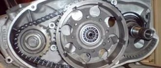
CRANKSHAFT. In the IZH-PZ and IZH-YUZ engines, the crankshafts are structurally different. The IZH-PZ crankshaft includes a connecting rod 4 (Fig. 10), cast iron flywheels 5 and 9, pins of the crank mechanism 6, axle shafts 8 and 10, a bearing of the lower part of the connecting rod 7. The drive sprocket is installed on the left axle shaft, and the electric generator armature is installed on the right one . The crank pin connects the halves of the flywheel. The tightness of the connection is achieved by pressing the mechanism components. The IZH-YUZ motorcycle engine consists of right and left crankshafts (Fig. 88). The shafts are fixed with keys and connected by a special remote flywheel. The axle shafts are attached to the flywheel with a coupling bolt, and after tightening they form a single part. After assembly, the crankshafts undergo a static balancing procedure. This operation reduces the impact of vibration and runout on the crankshaft bearings. Assembly and disassembly of the crankshaft of IZH-PZ, IZH-Yu3 engines may only be performed in a specially equipped workshop or in a factory environment. CYLINDER HEAD. All processes directly related to the operation of an internal combustion engine occur in the engine cylinder. Externally, the cylinders of motorcycles IZH-YUZ, IZH-PZ and earlier models consist of an aluminum jacket inside of which a special cast iron liner is inserted. Visually, the jacket is made with fins, the purpose of which is to cool the engine. The “jacket” design has special inlet and purge channels, which are connected to the carburetor and muffler using pipes. The lower part of the cylinder is attached to the engine crankcase using four studs. The cylinder head itself is attached directly to the cylinder with six studs. The inner surface of the sleeve is polished to a mirror finish on machines with an accuracy of 0.01mm. To seal the connection between the crankcase and the cylinder, a sealing paronite gasket is installed. The combustion chamber has a spherical shape. The cylinder head of the IZH-PZ engine has two holes intended for a spark plug and a decompressor. The IZH-YUZ engine has one hole for a spark plug. The tightness between the head and the cylinder is achieved through careful processing of the mating planes. There is no spacer between them.
PISTON (Fig. 14) The design of the piston includes a bottom 1, grooves for the piston rings 2, a skirt 3 and bosses 5 of the piston pin. To prevent rotation of the piston rings during engine operation, special pins are installed in the grooves under the rings. The design of the piston includes an oblique cut, the purpose of which is to give the skirt spring properties and to provide the necessary clearance between the piston and the walls of the cast iron liner. When the gap decreases, the piston may jam, and when it increases, knocking noises appear. An aluminum alloy with a high thermal conductivity coefficient and a low linear expansion coefficient is used as a material for the manufacture of the piston. PISTON RINGS. The main task of piston rings is to seal the gap between the piston and the cylinder walls, preventing the breakthrough of burnt gases. Piston rings are made of special gray cast iron and are heat treated. The ring has a cut called a lock. The design of the lock includes a groove for a pin, which prevents the ring from turning during operation. When installing a piston ring into a cylinder, it is necessary to control the gap in the lock to avoid shorting the ring under high temperature conditions when the engine is running. For smooth operation of the motor, several rings are needed. Therefore, there are 3 rings installed in the IZH-PZ engine, and two in the IZH-YUZ motorcycle engine. The piston ring locks are offset relative to each other. When the piston rings wear out, the ring grooves wear out and the gap between the piston and the cylinder walls increases. As a result, fuel consumption increases and engine power decreases. When using low-grade oils, the piston rings may burn and coke. The ring stops springing and performing its functions. Most often, the upper piston rings that come into direct contact with the combustion chamber burn. PISTON PIN. It is a hinge connecting the piston to the connecting rod. Material for production – steel grade 15X. After manufacturing the piston pin, it undergoes a carburization and hardening procedure. To reduce wear on the rubbing surfaces of the piston pin, the clearances must be such that the pin can rotate in the piston bosses and in the connecting rod when the engine is running. The piston pin is secured in the bosses with retaining rings inserted into grooves in the holes of the bosses. CASE (Fig. 12, 13) Combines parts of the internal combustion engine, clutch and gearbox. A motorcycle engine crankcase must be sealed, since processes associated with engine operation occur not only in the cylinders, but also in the crank chamber. Motorcycle crankcases are structurally made of two halves, which additionally include a clutch cover on the left and a generator compartment cover on the right. The IZH-PZ motorcycle crankcase is also supplemented with a gearbox cover. The crankcase halves are connected to each other with screws using bushings. The machining of the holes for the crankshaft bearings, as well as the gearbox bearings, is carried out in a crankcase assembled on control bushings. The tightness of the crankcase halves is achieved by treating the surfaces before assembly, followed by applying bakelite glue to them. The glue can be replaced with nitro paint or nitro varnish. The right crankcase cover has a hatch for access to the motorcycle generator. In the left cover of the IZH-YUZ engine there is a hatch for the clutch mechanism, which provides for filling oil into the engine crankcase. During operation, it is necessary to promptly remove carbon deposits from the surfaces of the cylinder heads and piston. This operation is performed every 8-10 thousand kilometers. Failure to carry out such maintenance in a timely manner leads to knocking in the engine and overheating.