Domestic motorcycles of the IZH brand, despite their age, are still popular in various parts of our country. This simple and unpretentious transport is especially popular among residents of rural areas. Not every imported motorcycle can start at +40 or -30, run on any gasoline, and when modified with a sidecar, it turns into a universal transport for a hunter or fisherman. Unfortunately, these motorcycles also have a significant drawback - low engine life. It’s rare that an IZh can work for several seasons and not fail. That is why below you will find step-by-step instructions on how to disassemble and reassemble the IZH Planet 5 engine.
Engine assembly IZH Planet 5
The engine assembly process occurs in the reverse order, with the obligatory condition that all technological features of the process are observed. When restoring the motor, do not forget that this is a precise mechanism and its main characteristics will depend on how carefully you approach the fitting and installation of all parts.
- All dismantled spare parts and engine elements are washed with solvent and an inspection is carried out. If serious chips, scuffs or other defects are found, these parts are replaced. If the left half of the crankcase or the right is damaged, then they are replaced in pairs.
- The joining surfaces are cleaned of traces of sealant or gaskets.
- The elements of the gear shift assembly are polished to a shiny surface.
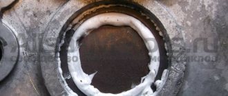
- We fill the left oil seal with grease and install it in place with the bearing ring, followed by a shaped washer.
- We install the retaining ring, after checking the accuracy of installation, proceed to the next steps.
- Next we mount the main bearing rollers and lubricate them.
- We put on the crankshaft and place a ball bearing lubricated with grease on it.
- We install spacer washers and follow them with a retaining ring.
- Let's see how easily the crankshaft rotates after lubricating it with engine oil.
If assembly at this stage does not cause any complaints, the following steps correspond to the reverse order of engine assembly. Please note that you need to purchase a complete set of new gaskets, and additionally lubricate the connecting surfaces with heat-resistant sealant.
Source
Preparing for assembly
Preparation for assembly can be divided into two main stages: measuring and, if necessary, eliminating the axial play of the tracer shaft and checking the suitability of the secondary shaft bearing for further operation.
The first stage is measuring and eliminating the axial play of the copy shaft
We put adjusting washers on the tracking shaft from the locking side. In my case, there were four adjusting washers, but you may have more or less, or maybe not... We move the locking bar to the side and install the copy shaft in its place. We put a standard thrust washer on the second end of the tracing shaft.
We place a new gasket (required) on the plane of the gearbox cover connector, on which you will later finally assemble the gearbox, and tighten the gearbox cover fastening screws with the required force.
We turn the engine over and measure the axial play of the copy shaft, the norm is 0.2-0.4 mm, but it will be better if you can ensure the axial play at a level of no more than 0.2 mm. Adjustment of axial play is accomplished by simply adding or removing shims.
I measure the play with an indicator. If you don’t have one, try measuring the backlash with a caliper; if you don’t have a caliper, so be it - measure by eye...
Second stage: checking the suitability of the secondary shaft for further use
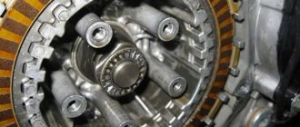
Under normal operating conditions, the secondary shaft bearing runs for quite a long time. But no matter how much we want and try, it wears out. It would be nothing if it weren’t for safety: if your secondary shaft bearing falls apart while driving, and it will certainly fly apart if you don’t change it in time, the gearbox sticks together with the rear wheel, and it’s tight and you’re grinding the asphalt with your butt...
Carefully, take out the secondary shaft over some tray and carefully inspect the shaft bearing raceway, the races and the rollers themselves. The working surfaces of the bearing and rollers should be free of holes, edges, signs of wear or overheating
The path must have a perfectly flat working surface.
Example of a secondary shaft race and race in perfect condition.
To facilitate reassembly, apply some kind of lubricant, such as lithol, to the treadmill and carefully place the rollers on the track and, turning it a little, insert the shaft into the cage. As soon as the sprocket splines rest against the edge of the oil seal, use a thin screwdriver in a circle to straighten the edge of the oil seal and push the shaft until it stops. And immediately, so that the shaft does not fall out, put the sprocket on it and secure it with a nut.
Tuning the IZH Jupiter engine
Before you start, you need to decide how much power you would like to give to your engine. If you are quite satisfied with the average power, then you will need a ZiD-200 resonator. But if you want to make the IZH Jupiter 5 motorcycle fast and powerful, start tuning the engine by installing a resistor from the SMB-5 “motoblock”.
Replacing the air filter plays a big role in engine modification. The better the air is cleaned, the more horses the engine will be able to produce. After all, the degree of engine overheating depends on the amount of incoming air. It is best to use imported air filters. They provide improved cleaning and longer service life.
Next you should work hard on the injection system. An excellent option is to install a “Planet” carburetor with a diffuser diameter of 0.32 cm. Two carburetors will provide much greater acceleration and good dynamics. We take the flanges securing the cylinder from the standard tube, grind out the aluminum studs, and cut off the flange from the carburetor from the inlet tube from the Planet.
We grind the ends of the cylinder heads on a machine, and press the cylinders themselves. The maximum permissible volume of PIC is 18 cubic meters. see Install factory copper layers under the cylinder heads. And we adjust the ignition advance angle to increase compression.
We use the second flange from the old carburetor. Then we weld the parts using “cold” welding. And finally, we modify the assembly to be compatible with the inlet channels. We fill all the cracks with epoxy liquid. Voskhod carburetors will ensure uniform traction. In this simple way, you can add not only a couple of extra horses to your pet, but also provide more lively dynamics, giving a good riding experience. The motorcycle is very reliable for everyday use, and if you provide good care, then breakdowns will occur very rarely.
In what cases is ignition adjustment necessary?
During the operation of the vehicle, the owner faces many problems. The most serious failure is related to the engine. In order to spend significant funds on major repairs, it is necessary to monitor the technical condition of the motorcycle and carry out preventive work, including adjusting the valves and valves (video author - Hana Rulyu).
If you do not monitor the SZ, then the motorcycle engine may not reveal its full potential and will not work at full capacity. This can lead to a reduction in its service life. An ignition adjustment is necessary if the engine is running poorly, the muffler or carburetor is firing. True, before setting up the SZ, you should make sure that the cause of the malfunction is in it.
It happens that the flywheel bolt, which connects the two halves of the crankshaft, comes loose, begins to play and does not work well. Sometimes he even cuts the key.
Setting up the SZ may be necessary after repairing the ignition switch Izh Jupiter 5. The installation and connection itself are carried out according to the diagram.
SZ diagram of the IZh motorcycle
Installation of bearings and seals
We install a retaining ring in the left half of the crankcase.
Depending on the model of the main oil seal, we install a spacer sleeve in the mounting hole of the main bearing, or, if the oil seal was initially wide (there are some), we heat the crankcase and, on the inside of the crankcase, place the oil seal until it stops against the retaining ring.
My engine had a regular narrow oil seal, so I put in a bushing.
Using a mandrel, install the main oil seal into the preheated crankcase.
Quickly, before the crankcase cools down, place the oil guide washer on the oil seal. The oil guide washer has a saucer-shaped profile. We place it on the oil seal so that the concave side faces us, and the curved side faces the clutch basket.
While the crankcase has not cooled down, we press the outer race of the main bearing into it using a mandrel.
If you are going to replace the main bearings with new ones, don’t be lazy: find a sheet of iron 7-8 mm thick, cut a wedge in it for the connecting rod, pass the sheet of iron between the cheeks of the crankshaft and use a mandrel to drive the main bearing onto the axle.
This way you will protect yourself from damage to the crankshaft. The main bearing has a very high interference and fits into the axle with a very large force. It is not uncommon for people to simply knock out the axle (the axle on the planetary crankshaft is pressed into the cheek) inside the crankshaft, but they were never able to put the bearing on.
Native made in USSR 2505 KM
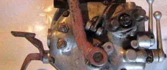
Purpose of the IZH Planet coupling
Clutch. the name of this node indicates the work it does. In our case, the crankshaft meshes with the gearbox of the IZH planet engine. The clutch should move smoothly, without jerking, which is necessary to start the motorcycle and smoothly change speed. In case of heavy loads, it protects engine parts from damage.
The clutch is located in the left half of the crankcase, under the left engine cover. To get to it, you need to drain the oil and remove the cover before removing the arms and unscrewing the mounting bolts. The clutch is always in working condition, the discs are tightly compressed by springs. The engine transmission consists of two sprockets. The small wire is located on the crankshaft. The big star led the drum. The connection is made by the motor circuit. The engine's gear ratio is 2.17 for all single-cylinder IZ models. Switching off occurs using a special device. The shutdown mechanism is installed in the right engine cover. The adjustment is made using this mechanism.
Photo report: Repair (repressing) of the crankshaft of the Izh-Planet motorcycle - SCOOTERS AND MOTORCYCLES
Due to a gross design miscalculation, the crankshaft of the engine of the Izh-Planet (SZD) motorcycle, having traveled some measly 5,000 km, successfully “grunted” (knocked). Even Chinese plasticine goes through many times more, but here is “Planet”. How so? Of course, to clarify the picture, it’s worth making a little reservation: The crankshaft, the repair of which will be discussed in this article, is slightly different in design from the original “planet” one, since it is from the SZD (motorized sidecar) engine. But in essence, there is practically no difference between these shafts and engines. The reason for the rapid failure of the crankshaft was that the bearing of the lower head of the connecting rod, due to a gross design flaw, was not at all lubricated with oil during operation.
Here, that same depression in the cheek, of unknown purpose. But the oil channel (ordinary chamfer) on the “native” connecting rod, the channel must be said: it was made to “fuck off”, and it’s not a channel in essence, but another Soviet bullshit ( Even the Chinese don’t allow themselves to do this). Through such a channel, lubricant cannot even theoretically flow to the bearing. Now look, if you put a new connecting rod with developed channels for lubrication, then all the same, the channels are blocked by the walls of the recess. Our task for today: Install a new connecting rod, instead of the old one, in the crankshaft, having previously taken care of its normal lubrication. And then, the whole thing must be carefully aligned using special measuring tools. First, the crankshaft must be disassembled.
We place the crankshaft on the sheet. We lay the sheet on some powerful beams so that the crankshaft journal hangs freely in the air, take a suitable mandrel, place it on the finger and use a heavy sledgehammer to knock the finger out of the cheek. After removing the finger from one cheek, take the second cheek, place it on the sheet and knock out the finger in the same way. Before removing the finger, remember the main rule: Never try to knock out a worn finger all the way through the second cheek! During engine operation, the working surface of the bearing pin of the lower connecting rod head takes on an elliptical shape, so if you decide to knock out the pin with a worn surface through the cheek, the result will be the same - you will violate the geometry of the hole for the pin in the cheek. Because of this, the new finger will no longer stay in such a hole! Previously, a new connecting rod was purchased from the online store (factory-made, not 100% made in China). We are looking for the thinnest and most worn-out diameter cutting disc for the grinder, prepare a container with water in advance, install the disk on the grinder and proceed to finalizing our connecting rod
Such a groove is quite enough to lubricate the bearing; as you can see, due to the timely cooling of the part with water, there are completely no traces of blue. After cutting the groove, we take the files and carefully sand all the burrs, sharp corners, “other jambs” both inside and outside. The connecting rod is modified, now you can start assembling. We lay any cheek on some flat surface (preferably wooden) and Using a mandrel, a heavy hammer or a small sledgehammer, we drive the bearing pin into the cheek. Be careful that your finger does not stick out of your cheek. We put the support washer on the finger, then we put the connecting rod with the pre-washed bearing there and put the second washer on top.
You shouldn’t push the cheeks together too much; bring them together so that there is a small gap (0.15-0.2 mm) between the connecting rod and the cheek. The final stage in all this work will be the final alignment of the crankshaft.
In case of any discrepancies in the thickness of the crankshaft, we either move the cheeks in the desired direction or compress them. Until the thickness of the crankshaft in all measurement locations is absolutely the same.
After we have equalized the thickness, we place the crankshaft on the prisms, install the indicator on the stand and proceed to the final one. We turn the crankshaft so that the indicator arrow shows maximum runout. We take a chalk and put a mark along the axis of the indicator. We take a metal plate, cover it with a sheet of some non-ferrous metal, in our case the role of the non-ferrous metal is played by a piece of lead. And lightly hit (where the mark is) with the marked cheek on the slab. Afterwards, we install the crankshaft on the prisms and check the runout, and repeat this until we can reduce the runout of the axles to the minimum possible value (no more than 0.03 mm).
Maintenance and repair
5.18 Reinstalling the crankshaft and measuring the radial clearance of the main bearings
Reinstalling the crankshaft and measuring the radial clearance of the main bearings
Selecting new bearing shells
Inspection of main bearings and connecting rod lower end bearings
Measuring the radial clearance of the main bearings
EXECUTION ORDER
1. Clean the backs of the bearing shells and their beds in the cylinder block and in the main bearing caps. 2. Insert the bearing shells into place, making sure that the protrusion on each shell matches the notch in the cylinder block or main bearing cap. Try not to touch the working surface of the earbuds with your fingers. 3. Radial clearance can be measured by two methods. 4. The first method (which is more difficult to implement as it requires the use of an internal micrometer set or an internal/external flaring caliper) involves installing the main bearing caps into the cylinder block/crankcase with the bearings installed in them. After tightening the mounting bolts to the required force, the inner diameter of each pair of bearing shells is measured (the crankshaft does not need to be installed). After measuring the diameter of each corresponding crankshaft journal, to obtain the radial clearance, it is necessary to subtract the second from the first result. 5. The second (more accurate) method involves using a product called a plastic gauge (Plastigauge). The gauge is a thin plastic thread of absolutely circular cross-section, which is crushed between the bearing shell and the crankshaft journal. After removing the lid and liner, the width of the crushed thread can be measured using a special scale printed on the kit packaging. The gap is determined by the width of the crushed thread of the meter. The measuring set can be purchased from a Saab dealer or vehicle repair shop. When using a plastic meter, proceed as described below. 6
Once the upper main bearing shells are in place, carefully reinstall the crankshaft. Do not use any lubricants at this stage; The crankshaft bearing journals and the surfaces of the bearing shells must be absolutely clean and dry.
7
Cut several pieces of plastic thread to the required size (the length of each piece should be slightly less than the width of the main bearing), and lay each piece on the corresponding crankshaft journal coaxially with the journal. A piece of plastic thread should be laid approximately 6 mm to one side of the center line of the neck.
8. After installing the lower main bearing shells, reinstall the main bearing caps and tighten the bolts in a progressive order to the required torque. Be careful not to move the gauge thread or rotate the crankshaft during the measurement procedure.
9. Loosen the bolts and remove the main bearing caps, being extremely careful not to disturb the crushed gauge threads or rotate the crankshaft.
10. Compare the width of the crushed plastic thread on each neck with the scale printed on the kit packaging. The measured value indicates the amount of clearance in the bearing. Compare the measured gap with the values given in the Specifications at the beginning of this Chapter.
11. If the clearance is significantly different from what is expected, the bearing shells may be the wrong size (or excessively worn if old shells are installed). Before you decide that you need to install liners of a different size, make sure once again that when measuring, no dirt or oil gets on the crankshaft journal or liners. If the crushed plastic thread of the meter is wider at one end than at the other, then this indicates the presence of a taper in the crankshaft journal. 12. If the gap value is outside those established by the Specifications
limits, select the thickness of the liners to ensure the required clearance. When calculating the required clearance, remember that it is always better to err on the side established by the Specifications
lower limit, since as the liner wears out, the thickness of the gap will increase. 13. If necessary, install bearings of the required size and repeat the procedure for measuring the bearing clearance. 14. Finally, carefully scrape the crushed plastic gauge thread from the crankshaft journals and bearing shells. To do this, use your fingernail or a wooden or plastic scraper that will not damage the bearing surface.
Final installation of the crankshaft
Assembling the crankcase halves
We degrease the connector of the halves, knock out the guide bushings a little so that they extend 5-6 mm above the plane. Depending on your desire, we assemble the checkpoint. Personally, I assemble the gearbox only after assembling the engine, it’s more convenient for me.
We apply any automotive sealant to the connector, install the second half of the crankcase, tap it with a mallet, install the gearbox cover and tighten the crankcase with bolts.
We do not pull the bolts anyhow, but strictly according to Feng Shui: we pull about a third of the force, first the middle crosswise, then the periphery, and gradually increasing the force over several circles, we tighten the bolts as much as is sufficient.
Installation of the cylinder-piston group
It is not advisable to remove the gearbox cover until the sealant has dried; there is no need to rush in this matter. It’s better not to rush things and install the cylinder while the sealant dries.
Add some motor oil:
To improve lubrication, it is advisable to drill holes in the piston bosses. But you don’t have to drill - it depends on your desire.
Install the piston pin retaining ring into the boss. Before installation, it is advisable to bend the locking ring a little and be sure to check how it fits after installation:
We heat the piston with a hairdryer and, using a mandrel, drive the finger into the piston so that it comes out no more than 5-6mm.
We look for an arrow-shaped mark on the bottom of the piston.
We orient the piston with the arrow towards the exhaust port of the cylinder (“towards the exhaust”), put the piston on the connecting rod, hammer in the piston pin and install the second retaining ring.
We insert the rings into the cylinder and measure the gap between the locks with a feeler gauge:
To improve the wearability of the rings and reduce noise from engine operation, it is advisable to chamfer the edges of the rings. If hunting gets too much trouble: place the ring on a flat surface and use a file to slightly round the edges.
We put the rings on the piston, fill the piston with the rings with oil, install a gasket under the cylinder (preferably with sealant), tighten the rings with a clamp. We cut the clamp out of tin and from the same tin we bend the bracket with which we will fix it.
After the rings go into the cylinder, unfasten the clamp, lower the cylinder and screw it to the crankcase.
We turn the crankshaft several times and if the piston moves in the cylinder easily and without grinding, lower it down a little, pour a little engine oil into the cylinder, install a new gasket on the cylinder and screw the head on.
We install the additional crankshaft support bearing in its place, place the required number of adjusting washers on top and secure it with a retaining ring. The adjusting washers must ensure axial play of the crankshaft within 0.1 mm.
Before installation, sealed bearings must be opened! Here goes the usual 304.
On the other side of the crankshaft we install a flange with a main oil seal. Pay attention to the oil channel through which oil flows to the right main bearing of the crankshaft. According to the good old collective farm tradition, this channel is sealed with sealant and the lubrication of the bearing stops. To avoid this trouble, place the flange dry without sealant and everything will be fine.
After the sealant has dried, you can begin adjusting and assembling the gearbox and replacing the clutch basket.
Numbers of bearings and oil seals for the Izh-Planet motorcycle engine 2, 3, 4 and fifth model.
Source
Engine IZH Planet 3, 4 and 5, disassembly, assembly for repair and tuning
When disassembling the engine, you must first drain the oil from it and remove it from the motorcycle frame; you must wash the engine thoroughly. To do this, it is advisable to use a high-pressure apparatus (car wash) with car shampoo. Having washed the engine and protected it from getting dirt inside, we proceed to disassembly.
We remove the right engine cover, remove the generator (by unscrewing the mounting bolts). Be careful not to damage the paronite gasket; remove the cover and disassemble the box. We take out the gears with the shafts and disassemble the shift mechanism, remove the control levers from the engine, and remove the clutch cover. We completely disassemble the clutch and remove the motor chain. We disassemble the piston, remove the cylinder head (by unscrewing the fastening nuts), then remove the cylinder. After this, remove the piston from the crankshaft, having previously removed the retaining rings and carefully knock out the piston pin. We place the engine on its left side and carefully, without damaging the heads, unscrew the connection bolts, using a powerful screwdriver. Then we knock out the centering halves of the crankcase half the length of the bushing.
Disassembled parts must be washed in gasoline and carefully inspected; damaged and faulty parts must be replaced with new ones. Clean the junction of the crankcase halves from old glue
On the oil seals (cuffs), pay attention to cracks and springs. Bearings should rotate easily without jamming and should not have any play
Having prepared serviceable parts, we begin assembly. We assemble the engine in the opposite order of disassembly. Be sure to heat the crankcase half to the same temperature, which makes assembly easier and preserves the crankcase surface from damage during pressing. The connection of the crankcase halves must be coated with BF-4 glue. When installing the piston on the crankshaft, it is advisable to heat it to a temperature of 60 degrees, this will help when inserting the piston pin. During assembly, you also need to lubricate the cylinder mirror and piston pin with engine oil.
How to adjust a motorcycle clutch?
As always, we delve into theory.
Junker's clutch type is multi-disc in an oil bath. On the left, on the gearbox shaft, sits a basket with alternating disks, thin steel and thick getinaks. They are pressed against each other using 5 (or 6) powerful springs. Getinaks disks are connected to the basket (and, through the motor chain and 2 sprockets with the crankshaft), and steel ones are connected to the gearbox shaft (and, through the gearbox, actually to the wheel). The springs are so powerful that the entire power of the engine, without slipping (and the disks are all in oil) is transmitted to the rear wheel. Next, when you press the clutch lever, the cable pulls the lever (it sits on the right engine cover - look), which pushes the steel rod (it passes through the axis of the drive sprocket, you can take it out and turn it in your hands), and this rod rests on that part a basket with disks, which is connected to the getinax disks, and they, overcoming the resistance of the pressing springs, move away from the metal disks. That's it, the clutch is loose. The engine with its getinaks disks rotates on its own, the steel ones with the gearbox stand still. Attention! There is more than one push rod. There are 2 of them, and between them there is a ball from the bearing (eliminates rotational force). Easily lost! Be careful when disassembling, otherwise you will end up with a failed clutch.
Now about the adjustments.
The clutch is adjusted NOT ON THE HANDLE, but by changing the force of pressing the discs against each other. The free play of the cable is simply selected on the handle. The force of pressing the disks against each other is regulated by preloading the springs, on which, for adjustment, “fungi” with a groove for a large flat-head screwdriver are put on. Access to these “fungi” appears by unscrewing the cap on the left engine cover (the hole through which you pour oil into the engine). And not to all of them at once, but only to a part – i.e. to adjust everything you will have to rotate the crankshaft with a kickstarter
IMPORTANT! All springs must have the same preload! Those. all mushrooms twist at the same number of revolutions
Or rather, half a turn - a turn is too large an adjustment step.
What to do if the clutch slips?
1. Make sure that the clutch handle has free play and that you have not unscrewed the adjuster on the handle so that the clutch is constantly depressed. 2. Open the left cover (no need to drain anything, at the same time check the oil level in the engine on the dipstick - it should be between the marks) and evenly, carefully tighten all the fungi half a turn. We start the engine, check the clutch operation, if it still slips, turn it off and repeat the procedure. At the same time, we look at the condition of the teeth on the textolite disks - if they break off on some disk, then it begins to rotate with the steel disks and the clutch operates. Good official Hyundai dealers will help you make the right decision. For an office move, movers are indispensable, I recommend Best-Loader.Ru. Wheel storage in Moscow. What to do if the clutch does not disengage?
1. See paragraph 1. higher. 2. See point 2 above, only the fungi are unscrewed half a turn. Well, the reasons for a driven clutch are natural wear of the discs, weakening of the springs, breaking of the protruding teeth on the getinaks discs, pulling out of the cable and LOSS OF THE BALL when repairing a motorcycle.
Now about what a semi-automatic clutch is.
When you change the speed, the shaft on which the gear shift paw sits turns, and with its fork protruding into the right cover, it presses on the clutch lever (the same lever to which the clutch cable fits and which presses on the steel rod), and thereby duplicates the pressure on the clutch handle by hand. And don’t blaspheme the semi-automatic in vain! A very necessary and useful thing! Firstly, your clutch cable has simply never broken on the road - it’s impossible to get going without a semi-automatic vehicle. Secondly, on the road, starting from 2nd speed, I never used the manual clutch at all - there was no need. When changing the speed, I simultaneously disengage the clutch, change the speed and smoothly engage the drive! (You make one move, oh IT makes 3!
) The only thing is that it’s inconvenient to get going with a semi-automatic vehicle if you’re not used to it, but it’s quite possible.
Assembly and disassembly of the IZH Planet 5 engine
Domestic motorcycles of the IZH brand, despite their age, are still popular in various parts of our country. This simple and unpretentious transport is especially popular among residents of rural areas.
Not every imported motorcycle can start at +40 or -30, run on any gasoline, and when modified with a sidecar, it turns into a universal transport for a hunter or fisherman. Unfortunately, these motorcycles also have a significant drawback - low engine life. It’s rare that an IZh can work for several seasons and not fail.
That is why below you will find step-by-step instructions on how to disassemble and reassemble the IZH Planet 5 engine.
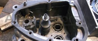
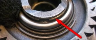
Following the diagram below, you can get to all engine elements in order to inspect or replace them. It makes sense to completely disassemble the engine if you need to get to the crankshaft or left oil seal.
Failure of the latter leads to a decrease in driving characteristics and smoking due to the presence of a large amount of oil inside the crank chamber.
Step-by-step disassembly diagram:
- Unscrew the spark plug and nuts from the top of the cylinder. We remove the cylinder with the piston.
- We drain the remaining oil in the engine and remove the engine from the frame (mounts in the front and rear), having first disconnected and numbered all the wires.
- We unscrew the left cover and remove as much as possible the gearbox and other accessible elements.
- From under the right cover we remove the generator, the final drive sprocket and the crankshaft oil seal.
- We remove all accessible parts related to the gearbox.
- On the right we find the screws that tighten the crankcase parts. We unscrew them together with the nuts of the two bolts.
- Use a rod of suitable diameter to push out the installation sleeves so that they partially remain in the grooves.
- Using a mallet, lightly tap along the entire plane of contact between the crankcase parts. If the parts do not move away from each other or come off partially, try inserting a mounting blade into the groove and tapping it without much force.
- Unscrew the locking plate and remove it.
- We take out the ring-washers, simultaneously noting their order.
- The left side of the crankcase can now be removed from the crankshaft. If the element does not give in, you can use light blows with a rubber hammer to help the parts separate.
- Using pliers, remove the retaining ring. To remove ball bearings, you will need a pipe or similar element, the end of which coincides with the outer race of the bearing. We lean it against the bearing and little by little knock it out of its mounting position.
- By lightly tapping, remove the guides of the gear shift units.
- We take out the retaining ring installed inside, and behind it the split remote ring.
- Press in the left oil seal. Similarly, we take out the main bearing ring installed on the right.
Engine disassembly is complete, now you can repair the IZH Planet 5 engine.
Engine assembly IZH Planet 5
The engine assembly process occurs in the reverse order, with the obligatory condition that all technological features of the process are observed. When restoring the motor, do not forget that this is a precise mechanism and its main characteristics will depend on how carefully you approach the fitting and installation of all parts.
- All dismantled spare parts and engine elements are washed with solvent and an inspection is carried out. If serious chips, scuffs or other defects are found, these parts are replaced. If the left half of the crankcase or the right is damaged, then they are replaced in pairs.
- The joining surfaces are cleaned of traces of sealant or gaskets.
- The elements of the gear shift assembly are polished to a shiny surface.
- We fill the left oil seal with grease and install it in place with the bearing ring, followed by a shaped washer.
- We install the retaining ring, after checking the accuracy of installation, proceed to the next steps.
- Next we mount the main bearing rollers and lubricate them.
- We put on the crankshaft and place a ball bearing lubricated with grease on it.
- We install spacer washers and follow them with a retaining ring.
- Let's see how easily the crankshaft rotates after lubricating it with engine oil.
If assembly at this stage does not cause any complaints, the following steps correspond to the reverse order of engine assembly. Please note that you need to purchase a complete set of new gaskets, and additionally lubricate the connecting surfaces with heat-resistant sealant.
Adjusting the clutch on a motorcycle
The clutch is regulated by changing the force of pressing the discs against each other, which, in turn, is regulated by preloading the springs. To do this, special “fungi” are put on the springs, which can be accessed after removing the cover on the left engine cover (oil hole). It is worth saying that in this way you can not get close to all the “fungi”, but only to some of them. All “mushrooms” can be adjusted by rotating the crankshaft using the starter
It is worth noting that absolutely all springs must be equally tensioned, i.e. each “mushroom” is twisted the same number of half turns
Thus, if the clutch is slipping, there are only two steps to follow:
- Make sure there is free movement of the handle. If it is not there, the clutch will be constantly depressed.
- Open the left cover, without draining any liquids, and tighten all the “fungi” evenly. After this, you should check the operation of the clutch. If slippage continues, it is worth repeating the procedure.
During adjustment, you should be careful and pay attention to various details, for example, the oil level in the engine, the condition of the teeth on the discs, etc. If after adjusting it there is no improvement, then you can begin the process of replacing the clutch
If after adjusting it there is no improvement, then you can begin the process of replacing the clutch.
It is worth noting that the malfunction of this element of the motorcycle should not be neglected, because if at the beginning of the day the clutch begins to slip, then after just a few hours of intensive motorcycle riding, it can completely die, thereby causing harm to the vehicle as a whole. After all, small particles of burnt clutch discs get into the oil, along with which they are sent to the precision joints of the liners, connecting rods and pistons, thereby damaging the engine
Therefore, if the time has come to replace the clutch, it should be done immediately.
With constant use of the motorcycle and long mileage, the basket itself wears out along with the clutch - wear appears on the edges of its longitudinal slots. Its appearance in these places makes it very difficult for the clutch discs to move. A shallow hole can be corrected using a regular file, however, this is a completely extreme case; still, if it appears, it is better to install a new basket.
So, there are different types of motorcycle clutch, however, the most common type is the multi-plate clutch in an oil bath. This is what is most often installed on motorcycles. Therefore, we will consider replacing the clutch using the example of a multi-disc clutch.
Crankshaft alignment
The crankshaft has been assembled, all that remains is to eliminate the runout of the shafts (balance), many people think that you can’t do this without a lathe, but everything ingenious is simple.
Measure each neck with a caliper as shown in the photo below, usually they are the same size, but sometimes they are slightly different in size. This dimension must be taken into account when aligning the crankshaft.
Photo. We measure the crankshaft cheeks.
All that remains is to attach the rod to the crankshaft cheek as shown in the photo below. It will be like this, first place the barbell on one cheek and press it with your finger, the barbell will lie perfectly flat on the cheek, if this cheek is shifted upward, a gap will appear between the barbell and the second cheek. If the cheek is lower, the bar will lie slightly obliquely.
Photo. A motorcycle crankshaft with a rod is shown; the arrow shows the gap between the rod and the cheek.
Your task is to achieve alignment of the crankshaft cheeks without gaps by applying the bar alternately to each cheek. The photo below shows how you can move the crankshaft cheek with a hammer blow. Just be sure to take into account the strength of the crankshaft cheeks, the crankshaft on which I am showing from a cross-country ChZet, it is hardened and is not afraid of impacts. But most of the crankshafts from road motorcycles have soft metal, so you can only hit the place where the bar is not applied.
Photo. This way you can move the crankshaft cheek.
If one cheek of the crankshaft turns out to be larger in diameter than the other, then when centering the crankshaft, take into account the gap between the cheek and the rod; this gap should be visually the same when applying the rod to the larger cheek on both sides.
Photo. The crankshaft of the motorcycle is centered, the rod lies without gaps on the crankshaft cheeks.
If you do everything right, everything will be correct, you will save money on a new crankshaft by replacing only the connecting rod on the old one, for this you only need your hands and a smart head.
Main stage
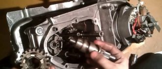
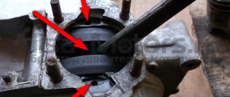
As noted in the assembly diagram of the Izh-Planet 5 box, further disassembly operations are carried out above the insides of the roof of the unit, since the secondary shaft and sector could remain in it. If it is necessary to remove them, you need to straighten the petals of the lock washer, unscrew the nut, remove the star and washer. Holding the gear very carefully to prevent the shaft from jumping out, the cover is moved to a clean and flat surface with the gear facing up.
It is worth noting that the bearing of this part of the assembly does not have a retaining ring. Therefore, when removing the shaft with bearing, the rollers may fall out, so be careful. If the specified element has exhausted a decent service life, there is a risk that when dismantling the secondary shaft, the outer ring may jump out of the seat and remain on the rollers. Next you need to start pressing out the oil seal. To do this, the installation rings are removed from the hole in the cover, after which the outer ring of the bearing is removed.
Required Parts
In order for the ignition system to work correctly, a number of auxiliary parts are required. They are listed below:
- Switch for BSZ VAZ cars. You should not choose exclusively from the low price segment. The Astro switch has a lot of positive reviews;
- Hall Sensor. The best option for Jupiter 5 is a similar manufacturer VAZ. By purchasing it in branded packaging, you protect yourself from counterfeits;
- Ignition coil with two terminals. You should choose between the gazelle engine number 406 or Oka with an electronic ignition system;
- A pair of silicone armor wires with rubber caps;
- The modulator is a butterfly-shaped plate made of iron.
Modulator
The most difficult stage is the production of the modulator
It is important to maintain the required shape. The more reliably the required dimensions are observed, the lower the likelihood of problems occurring after implementing the system, that is, there will be no need to adjust it using a file
The ignition timing must match on any cylinder used.
The bolt hole must be located in the middle. Otherwise, the engine operation will not be synchronized. It is also recommended to check the integrity of the crankshaft bearings. If you find defects, you should immediately replace it.
The contact ignition is not able to work normally if the bearings are damaged. The thickness of the part should not exceed one and a half millimeters. If it is thin, it will not be possible to avoid deformation, and if it is thick, it will come into contact with the surface of the hall sensor housing.
To create the plate, it is allowed to use any material except steel. Aluminum and others should not be used as they are not magnetic. The drawing that must be followed can be found in the public domain. The presented diagram will be useful to those people who decide to modernize the vehicle ignition device. Below are methods for installing electrical ignition devices in Jupiter.
It must be turned by a professional turner. He will make a simple disk and draw on it the markings of elementary distances between the corners. Then, in accordance with it, you will cut out the necessary sectors at home. The cost of the modulator is seventy rubles.
It is not advisable to use an ordinary plate, since its width is less than twelve millimeters. This will not be enough to fully accumulate the energy resource in the coil. Of course, it can be installed, but achieving four thousand revolutions per minute will become impossible.
In addition to the above you will need:
- A stud with an applied thread of seven millimeters, pitch 1, as well as a pair of nuts with washers of the corresponding parameters. The priority material for these components is brass. This is explained by the least magnetization of the plate from the generator rotor. If you use a standard bolt, then difficulties may arise with the introduction of ignition. The bolt tends to follow the modulator as it is tightened. However, it is necessary to observe the leading indicator, maintain the same position of the rotor and modulator, and tighten the bolt. It is advisable to use a pin, since many are not able to perform all the necessary actions in total;
- A set of wires with connectors for ignition without contact from VAZ. This part can be purchased or made with your own hands.
Retro style
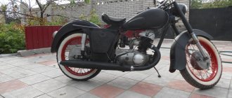
Nowadays the fashion for old and vintage cars and motorcycles is actively developing. Models from 30 to 50 years ago are kept in barns and distant villages to be restored to their original form. The idea of this style is a complete or partial restoration of the motorcycle to its factory appearance. The closer and better the work is done, the better the tuning of IZH Planet 5 with your own hands looks photo:
Do not think that it is so simple, because even for such a relatively new model, it is becoming increasingly difficult to find original spare parts. Particularly expensive are fragile dashboards, original trunks and dented gas tanks. You'll have to hunt for these details. It will be very expensive to restore Soviet chrome and paint all chips and scratches. This style is suitable for true connoisseurs of the brand and those who prefer to spend hours and days in the garage.
Other faults
It happens that disassembling/assembling the Izh-Planet 5 box may be necessary if the fourth speed disappears. This is often due to broken bearings on the output shaft. Such a nuisance occurs due to the presence of axial play, displacement of the bearing assembly, or its failure. You can try to fix the problem in the same way as repairing the second gear. If this does not help, you will need to completely disassemble the unit.
When the speed switch jams from a high range to a low mode, the spring system of the switching mechanism has failed. It needs to be replaced. Strained operation of the unit after assembling the Izh-Planet 5 gearbox indicates incorrect installation of the adjusting washers. To avoid this, it is necessary to mark and record the previous placement of these elements during the process.
Recovery process
When the euphoria of the purchase wears off, a lot of questions arise regarding its repair and restoration with your own hands.
The main task of the new owners:
- Restore the electrical system - and there are no particular problems with this, since the electrical wiring of IZ Jupiter 2 and Planet of the second and third generations is identical and interchangeable;
- Starting the engine is a more difficult task due to the need to overhaul the power unit and the availability of spare parts;
- Return the motorcycle to its original appearance. It is also quite complex and, perhaps, the most painstaking work of the entire project.
The video below shows the restored models.
Factory layout for several generations of motorcycles
- Whether to switch to contactless ignition or change the voltage from 6 to 12V is up to you to decide.
- If you have such a desire, and you manage to get your hands on a native Izhevsk generator 281.3701, then the replacement process will be much easier.
- The publication IZ Jupiter 3 wiring diagram will familiarize you with the details of the alteration.
central locking
Let's consider the process of restoring the central lock, since in most surviving models it is faulty.
Appearance of the headlights and controls of IZH Planet 2
The difficulty is that finding the original lock is very difficult, almost impossible. Moreover, at 6V, since later the Izhevsk Motor Plant transferred all subsequent models to 12-volt equipment.
This is what the filling of the original 6V ignition switch looks like
Therefore, many motorcycle owners adapt parts from later versions of Planets and Jupiters.
The difficulty of installation in this case is as follows:
- Uncertainty about whether the lock will work;
- How to properly connect wires.
Wiring diagram for IZH Planet 2 to the lock
Headlight
Many owners do not attach importance to adjusting the head light, believing that a working light bulb and intact glass are enough for “driving” during daylight hours.
Using this scheme it will be easy to connect all consumers
In fact, this is not so, and adjusting the light is not only desirable, but also mandatory, especially since it can be easily done independently, spending no more than half an hour of personal time on it.
Scheme for adjusting the angle of luminous flux
We recommend reading:
Tips, instructions, important features of the process
Hello reader, before you start reading this, I recommend stocking up on more than one cup of tea and a lot of cookies, because the article, in my opinion, is included in the “dull” group because there is a lot to write, and I would like not to miss anything in order in the future, the person who read this did not make the mistakes that I made. So, let's begin. I didn’t write about all this in the description, because there’s a lot to write, and there’s no point, it doesn’t fit into the description, but it’s in a separate article, and so, as was written earlier, the motorcycle was “revived” after a long 5 -year-long downtime, as I remember now, the weather was bad, it was raining, in general it was early spring, my friend and I remembered it, and something became interesting, is it true that our motorcycle industry is as bad as they say, that motorcycles are not reliable, they say, as long as you ride, you lie under it. However, closer to the point, the motorcycle started up almost immediately, it was necessary to do basic things, pour fresh gasoline, blow out the spark plug, check the ignition and electrics in general, because the downtime was not short, and anything could happen, and he got up to this downtime not just like that, I knew about it too. But strangely enough, the motorcycle started up immediately, without problems or complaints, it worked smoothly, and it smelled, truly smelled like our two-stroke engine smell, I think everyone who lived in a village or region knows what our Planet or Jupiter smells like when passing by , this is a smell that takes you somewhere to childhood or something, but let’s return to the topic. They started the motorcycle, I rode literally 2 kilometers and it stopped, the coil got hot and eventually burned out, I had to roll it, I struggled with it for about a week or two, took it to mechanics and just knowledgeable people, but no one could understand what was wrong, but there was a person who could still do it. The problem was in the wires on the generator, they were mixed up in phases, anyone who knows the structure of the generator on the Sovki will understand what I mean. Because of this, the ignition coils (popularly called "women") burned, and often also the spark plugs. Then the season went on, the whole season without a single breakdown or a single complaint, the motorcycle surprised me more and more every day, and completely
Improved ride quality
The icing on the cake, and in our case the final touch of tuning, is the improvement in driving performance. Some of the tuners approached this issue earlier when they sawed the frame of their motorcycle or raised the tail of a future crossover. For the rest, first of all, you should get rid of your original tires. Among its advantages, only wear resistance can be noted, for which you pay with your safety. It is both universal and useless. The lugs are practically useless; if they get into a mess, under normal conditions on the highway it is noisy, but relatively holds the road, turning into a killer on a wet highway.
Therefore, without hesitation, we throw it away and purchase road, cross or all-purpose tires, based on your requirements. The second point is the suspension. If everything is generally clear with the rear shock absorbers, they are extremely reliable and, in addition, have stiffness settings, then the front fork does not leak only for those who have chosen a different brand. There are two ways to get out of this situation. The first is to add thicker oil. The second is to carry out a complete overhaul of the feathers and replace all parts. Both options do not last long, so the most demanding owners simply change the fork to an imported one, while the rest endure all the shortcomings of their iron horse.