There are quite a few models and varieties of Minsk motorcycles, but they are all equipped with similar generators that operate on the same principle and also provide an automatic ignition system. Therefore, most often, if the engine does not start, the problem lies there. Setting up the ignition of a Minsk motorcycle is not particularly difficult for an experienced driver or mechanic, but those motorcyclists who are encountering this problem for the first time will need some advice. With their help, you can easily adjust the ignition of your Minsk motorcycle and put it in order, so that your iron horse can again carry you along the road with the breeze.
The main thing in working with ignition in Minsk is to determine what the problem is and whether you can help the motorcycle with your own hands. Most often, the problem occurs in the breaker or due to an insufficiently strong spark of the outline. We will look at these points in more detail.
We adjust the contact gap in the breaker:
- By turning the rotor, we achieve the maximum distance between the contacts.
- Unscrew the screw securing the contact stand to the cover.
- We turn the eccentric until we get a gap of 0.35 - 0.40 mm. We measure the gap using feeler gauges.
- We set the ignition timing.
To do this, raise the piston to a distance of 3 mm from TDC. Next we look for the moment of rupture. Slightly unscrew the bolts in the stator. Then we place a small sheet of paper between the contacts. When the sheet falls out, the breaking point has been found. We tighten the bolts into place and check the distance between the contacts again.
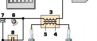
Scooter ignition
Ignition from a scooter on the Izh Jupiter can work without a battery. Before setting it up, we need three details:
- Scooter switch;
- Ignition coil;
- Inductive original sensor (must have a single wire output).
The DC switch is powered from a 12 W network, also the on-board network of the motorcycle is 12 W, the switch has 4 wires, the first of which is plus, the second is minus, the third is to the coil, the fourth is to the inductive sensor. We reliably connect the negative wire from the switch to the negative wire from the motorcycle (ground), and connect the positive wire that goes to the standard coil to the positive wire of the switch.
Ignition coil connection:
- We connect the negative wire to the ground of the motorcycle;
- we stretch the second wire to the switch and connect it to the output under the coil
In order not to pull an additional wire to the inductive sensor through the entire engine, you can use the wire that connected the contact group and the standard ignition coil.
To do this, you need to take the wire from the switch that goes to the inductive sensor and connect it to the wire that went to the standard coil. Next, remove the capacitor and connect the inductive sensor
Particular attention must be paid to positioning the generator cover. It needs to be installed properly and not touch anything when rotating.
To do this, you need to shorten the cam a little and also make notches on it that prevent the modulator itself from turning. It is also worth observing the parameters of the gap between the modulator and the inductive sensor, which should be within 1-1.5 mm. When installing the ignition, you need to know that the spark strikes when the modulator leaves the sensor, and not at the input.
Once electronic ignition from a scooter is installed on a motorcycle, its performance will improve significantly. In particular, it will start much better (this will be especially noticeable when the battery charge level is low). Speed gain will also improve noticeably. The motorcycle will idle smoothly, which indicates proper engine operation.
Adjusting the outline
A correctly adjusted outline will allow you to get maximum spark during ignition. Adjusting the outline is quite a complex and time-consuming task , so if you are not sure that the problems in the ignition are related to it, you should not disassemble it.
After adjusting the contacts, it is necessary to determine the size of the spark. If it does not change during the contact adjustment process, the adjustment can be considered completed. But, provided that the spark changes, we continue to work.
To adjust the outline you need:
- Unscrew the outline bolts, but not completely.
- If the spark increases with increasing distance between the contacts, turn the outline plate clockwise; if it decreases, turn it counterclockwise.
- Check the distance between the contacts.
- Install the ignition and check the spark.
- We perform these actions until we get a strong spark that will not change when the distance between the contacts changes.
The process of ignition control is quite complex and it may not be possible to do everything well the first time. Therefore, it is worth seeking advice from more experienced drivers who will not only tell you how to do it better, but also show you.
Motorcycle Minsk, operation and repair.
>> ELECTRICAL EQUIPMENT, IGNITION SYSTEM Next >>
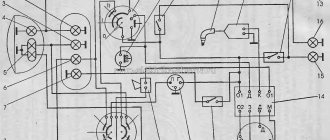
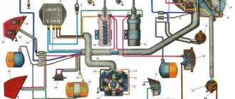
Rice. 3.12. Ignition system.
On motorcycles M103-M106 and 3.111 a contact (mechanical) ignition system was used.
The ignition system consists of a generator ignition winding, a breaker, a capacitor, an induction coil, a high voltage wire, an anti-interference device, a spark plug, a central switch and low voltage wires (Fig. 3.12).
When the breaker contacts are closed, the ignition winding is short-circuited to ground and the current flows through circuit 1: ground - generator winding - breaker - ground. When the contacts open, the current flows through circuit 2: ground - generator winding - terminal A - red wire - terminal H - primary winding of the induction coil - ground. If the ignition is turned off, then terminal 4 in the central switch is connected to terminal 3 and the current, bypassing the primary winding of the coil, which has resistance, goes to ground through terminals 4 and 3 of the switch.
Ignition system devices. The B-300 induction coil consists of a core, primary and secondary windings, a housing, a cover, coupling screws and terminals.
The coil is installed in a metal bracket, which is attached with two bolts to the frame bracket. The ground terminal is connected to one of these bolts, so the frame bracket must be well cleared of paint where it connects to the coil bracket. The high voltage wire is secured to the coil output terminal using a rubber sealing sleeve and nut.
A faulty coil cannot be repaired and must be replaced. The only exception is a wire break from the low voltage terminal inside the coil, which can be eliminated by soldering. Do not allow water to come into contact with the reel, as this may cause interruptions or failure of its operation. If water does get in, the coil should be dried in the sun or in a warm room for several hours.
Failures of high voltage wires include damage to the insulation and destruction of the core, especially at the ends. If the end of the wire is damaged, it should be carefully cut off with a knife.
Rice. 3.13. Spark plugs: a - hot; b - cold; c - with a protruding thermal cone (skirt); 1 - length of the threaded part; 1 - protruding part of the skirt; 2 - sealant; 3 - side electrode; 4 - central electrode; 5 - skirt; 6 — body; 7 — insulating heat sink washer; 8 - glass sealant; 9 — mesh knurling on the contact rod; 10 - insulator; 11 — contact rod.
The spark plug (Fig. 3.13) consists of a housing, an insulator and electrodes.
For uninterrupted operation of the spark plug, the temperature of the lower part of the insulator (skirt) must be within 500 - 600 ° C. In this case, carbon deposits burn on the insulator (self-cleaning), and the color of the insulator changes from light gray to light brown. If the temperature of the skirt is below 500 °C, then carbon deposits are deposited on it, causing current leakage to ground (carbon deposits - conductor) and interruptions in operation. If the temperature exceeds 700 °C, then premature ignition of the mixture from the hot insulator occurs - glow ignition.
The correct selection of spark plugs improves engine performance, makes it easier to start and increases power. A well-chosen spark plug, removed from an engine running under load (at least 2 km of driving at a speed of 80 - 85 km/h), should be dry and have a skirt color from light gray to light brown. Since an engine in operation necessarily has deviations from the norm (even if insignificant), at the moment it may be better suited not to a factory-installed spark plug, but to another one that is close to it in thermal characteristics.
Malfunctions of the spark plug include heavy deposits of soot and soot on the skirt, shorting of the electrodes with soot or melted metal (bridge), an increase in the gap due to burnout of the electrode, pitching or cracking of the insulator. When eliminating a bridge or soot on an insulator, the causes of the malfunction must also be eliminated. If there are cracks or movement of the insulator, the spark plug is replaced with a new one. Sometimes cracks in the insulator may be invisible and without a load (when checking for ground), such a spark plug can produce a normal spark, but under load (in the cylinder) it will work intermittently. If there is any doubt about the serviceability of the spark plug, it is necessary to install a rubber plate between its electrodes and check for a spark. For a working spark plug, the spark will jump between the central electrode and the body, and for a faulty spark plug, through the insulator outside or inside the spark plug.
Radio interference protection device SE-12 or A-14 is used to reduce radio and television interference created in a high voltage circuit.
It is based on a resistance of 12,000 - 14,000 Ohms, mounted in the body of the spark plug tip. Shielding the tip with a metal casing (A-14) additionally reduces the level of radio interference. The device improves the performance of the spark plug and its installation on a motorcycle is mandatory.
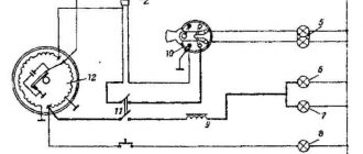
The central switch VK-863 (Fig. 3.14) is installed together with an audio signal on the bracket of the upper bridge. Has three working positions:
0 - the motorcycle and the entire electrical system do not work;
1 - the ignition circuit is turned on, the braking signal and the direction indicator circuit are on (when switch P201 is turned on);
2 - the side light lamp turns on when driving on illuminated streets, the speedometer and rear light are illuminated (through the throttle) and the high/low beam lamp turns on when the P200 switch lever is moved to the right/left.
To remove the central switch, disconnect the cover, remove the plastic cover and unscrew the round nut. To remove the cylinder, you need to insert the key and turn it all the way to the left (counterclockwise). Insert a needle into a small groove on the perimeter of the cylinder and press the end of the lock washer down 2 - 2.5 mm, turn the cylinder all the way to the left and remove it along with the key. To remove the rotor, unscrew the screws securing the arms and, carefully, so as not to lose the balls and the retainer spring, remove it from the housing.
During assembly, the rotor must be rotated so that its leads connect terminals 1 - 2 and 5 - 6 (Fig. 3.12). The cylinder is installed together with the key. First, place the lock washer and align the groove in the bottom of the cylinder with the protrusion in the body, and then insert the cylinder and, lightly pressing it down, turn the key all the way to the right, and then to the left.
Rice. 3.14. Central switch VK-863: 1 — locking ball; 2 - rotor; 3 — clamp spring; 4 — rotor driver; 5 — contact plates; 6 — cover; 7 — bracket; 8 - wire; 9 - terminal; 10 - panel; 11 — protective cover; 12 — locking plates; 13 - groove in the body; 14 - cylinder; 15 — lock washer; 16 - nut; 17 — body; 18 — fixing protrusion in the body
Maintenance of the switch consists of tightening the threaded connections and periodically (once a season) lubricating the cylinder and retainer balls with lithol or consalin. After 2000 km, you can, without disassembling the switch, pour a few drops of autol into it through the key hole.
The following switch malfunctions are possible:
1. Stiff cylinder rotation caused by lack of lubrication or sand. The malfunction can be eliminated by flushing the switch and lubricating it.
2. Weak fixation due to weakening of the clamp spring or1 development of grooves in the housing. The spring should be stretched or the groove in the housing should be filed.
3. Sticking of the cylinder as a result of wear of the lock plates or 1 key. It is necessary to remove the cylinder along with the key and carefully file away all protruding plates. If the locking plate breaks, it should be removed. Jamming can be caused by the rotor arms being loosened or the contact plates being bent, causing the arm to rest against the end of the plate. The driver screws should be tightened or the contact plates should be straightened.
4. Fuzzy switching - the ignition does not turn on, the lights do not turn off, etc. - may be caused by loosening of the leash or contact plates that need to be riveted. The panel may break (usually with the terminal, which can be fixed with glue).
If you lose the ignition key, you can get to the garage by disconnecting the red wire from terminal 4 (Fig. 3.6) and insulating it.
Some tips for setting up the ignition on a Minsk motorcycle
- Before you move on to setting up the ignition, you should make sure that this is the problem. It is better to start repairs by checking the elements, the setup of which is much easier, and which more often fail. Even experienced specialists will not immediately determine whether the problem is in the ignition or the carburetor is clogged.
- Study the ignition mechanism thoroughly.
- Check the condition of the spark plug. Perhaps that is where the problem lies.
- When adjusting the ignition, it should be remembered that when the crankshaft rotates clockwise, the ignition interval increases, and counterclockwise, it decreases accordingly. Before adjusting the outline, the ignition timing is set.
Using these instructions and recommendations, ignition control will no longer be a problem. You can see the setup procedure in more detail in the video.
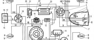
Operating principle of the electronic ignition system
The latest generation of Minsk generators significantly increases the power of the electricity source.
This ensures uninterrupted functioning of all elements of the system. In all speed modes, electricity consumers have reliable supply. New generators differ not only in their functionality, but also in their structure. Different motorcycle models have different types of alternators. But they are similar in appearance, which allows you to attach them without matching the model.
The only thing to remember is that when changing the generator to another type, it is necessary to regulate all other elements.
Electronic ignition is non-contact. The design features of Minsk do not provide for the presence of a battery. The ignition system operates on the basis of GPT. The work uses a switch unit - stabilizer and an induction sensor.
A voltage stabilizer is used to regulate the amount of current supplied to lighting and sound signals. The switch and the stabilizer are not interconnected in their functions.
The Minsk ignition system works through the connection of such elements as:
- candle,
- voltage transformer;
- induction sensor;
- resistance;
- indicator lamps;
- wires
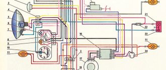
A properly configured ignition system is the key to ensuring that the motorcycle will start even in winter. The absence of a battery makes life easier for a motorcycle owner to some extent. There is no need to think about periodically recharging the battery. The Minsk motorcycle wiring diagram shows the relationship between individual elements.
How to set up a pakko carburetor
The carburetor ensures engine operation in all modes with its four systems. Let's look at them.
The float mechanism is shown in Fig. 1. The floats 1 are connected to each other and, through a lever 2 fixed on the axis 3, act on a steel needle 4, which locks the hole in the valve seat 5. The two floats create sufficient lifting force, which increases due to the lever connection of the floats with the needle - and this guarantees reliable valve closure.
Another feature: the axle is located behind the floats, and therefore when the motorcycle moves uphill, the fuel level automatically increases slightly, which improves traction characteristics, and when moving downhill, it decreases.
The starting device (Fig. 2) serves to enrich the mixture when starting a cold engine. To turn it on, you need to press lever 2. Then fuel from the float chamber through the nozzle 6 of the starting device is sucked into the well and emulsion tube 5, where it mixes with air and passes into cavity 3 under the piston. Here, air is added to the emulsion, entering through hole 4 on the inlet pipe of the carburetor, and the mixture of the required composition enters the outlet pipe. The device operates automatically. There is no need to manipulate the throttle handle when starting: to avoid temptation, it is better not to touch it at all. After a short warm-up, lift the starter lever to its original position. In this case, piston 1 will go down, and the rubber sealing washer on it will block the system.
The idle system (Fig. 3) is not much different from the generally accepted one. In this mode, the throttle is almost completely lowered - there remains a gap of only about 0.8 mm under it. The amount of air passing through it is insignificant; its speed in the nozzle zone is low and therefore does not cause fuel leakage. The vacuum near the gap reaches its greatest value - and therefore channels 2 and 3 of the idle system are brought out here. Fuel enters through jet 5, and air through the hole on the inlet of the carburetor, the well of the idle speed adjustment screw 4 and the well of jet 5. Here the fuel and air are mixed, air is added to this mixture through channel 2, and through channel 3 it flows to the outlet carburetor Mixing with the air passing through the throttle slot, the air-fuel emulsion becomes suitable for idling the engine. The quality of the mixture (degree of enrichment) is regulated by screw 4, and its quantity by a screw that limits the movement of the throttle.
The design and principle of operation of the carburetor
The main purpose of a carburetor in any internal combustion engine is to mix fuel with air in certain proportions. If they are violated, the engine starts to work incorrectly or stops completely.
Chainsaw carburetors of different brands have some differences in design, but the main components of this part, as well as the principle of their operation, are approximately the same:
- The base (body) is a wind tube with an air damper located across it. Its purpose is to regulate the air supply to the inner chamber.
- The float chamber is a container that holds the fuel mixture in a stable state.
- The atomizer is the area where air and fuel come into contact. Fuel enters the atomizer from the float chamber through a nozzle.
- A diffuser is a part that increases the speed of air flow, with the help of which the required pressure is maintained. The diffuser is located in the narrowed part of the tube.
The operating principle of the carburetor is as follows:
- After the engine starts, the damper opens and air enters the channel.
- The flow rate and the level of the float in the chamber are regulated by the position of the damper, due to the difference in pressure in the float chamber and the air channel.
- Fuel from the float chamber is sucked into the nozzle and then into the diffuser. Moving through it, the air captures the incoming fuel.
- The resulting mixture is fed into the cylinder cavities through the intake channels.
Engine tuning Minsk
An important principle of increasing motorcycle power is increasing cylinder volume . Since the motorcycle discussed in our article has a light, small-capacity engine, a couple of horses can be raised by boring the cylinder walls and replacing the piston with a larger size. At the same time, it will be useful to use new rings coated with chrome, as they minimize friction on the surface of the cylinder, thereby increasing engine life. The next step to increase power is to replace the fuel system. The standard carburetor has a primitive design and does not allow the engine to get maximum power, so you can replace it with a Keihin PWK flat-choke carburetor .
Compared to analogues, its flat throttle allows you to speed up the flow of the intake mixture by 30%, as well as an additional jet that comes into operation when the gas is fully opened, which, together with a good air filter, is an excellent do-it-yourself Minsk motorcycle tuning. In order not to disrupt the operation of the new carburetor, it will be useful to treat all intake channels from rough deposits and roughness that impede air flow.
It is worth paying attention to two main ways of tuning a Minsk motorcycle:
Firstly , the intake system can be significantly improved by installing a reed valve at the inlet of the cylinder after the carburetor. The reed valve will prevent the mixture from being pushed back into the fuel system when the piston makes its power stroke.
Secondly, replacing the standard muffler with a resonator made of sheet steel will not only allow you to lose weight, but also very significantly increase the power at medium and high engine speeds of the Minsk 125 motorcycle. Such tuning of the Minsk will not only improve power, acceleration and maximum speed, but and will make your faithful friend much more economical!
A good preventative measure for the engine would be to replace all its bearings with imported analogues. Due to the increased power of the motorcycle, the load on them will increase. Any Japanese bearing company has decent workmanship and a huge selection.
Motorcycle parts of all models
In the section with spare parts for a motorcycle, you can buy everything that a motorcycle might need - from light bulbs for the dashboard to a motorcycle engine. All advertisements for sale:
- accompanied by several photos of spare parts;
- must contain the price;
- provide the seller's contact information.
New and used motorcycle parts are offered by both individuals and companies - choose from more than 30,000 offers for all famous brands: Yamaha, Suzuki, Honda, BMW and other motorcycle vehicles.
Initial adjustment and starting to use the saw
Most instruments come pre-configured by manufacturers.
During the running-in process, the correct operation is checked:
- When starting up for the first time, you need to ensure that the chainsaw operates in a gentle mode. A few hours after the start, it is recommended to cut small branches and trunks up to 10 cm thick.
- The chainsaw must start correctly, ensure a stable rotation speed of the sprocket and a smooth increase and decrease in power.
- Fuel consumption must correspond to the power used and in practice the saw should not go out, “sneeze”, smoke or run jerkily.
- There should be no extraneous knocks, pops or noises when the engine is running.
The following rules will help you stay safe:
- Mix gasoline and oil in accordance with the proportions specified by the manufacturers.
- Do not prepare the mixture in advance. The properties of gasoline and oil in a mixed state change over time. The exception is fuel for intensively used tools, however, even here the norm of 7 days should not be exceeded.
- Use oil designed for the chainsaw brand engine. A fuel mixture with a non-standard composition will damage it.
- When preparing the fuel mixture, take into account the influence of climatic conditions on the components.
Painting a motorcycle at the car service center "Painting Auto Minsk"
Painting a motorcycle is not a simple and lengthy technological process. Sometimes car enthusiasts, trying to reduce the cost of repairs, paint the motorcycle themselves. But often this leads to a sad result. The motorcycle part is damaged, and correcting the errors increases the cost of painting the motorcycle. Also, if there is minor damage, it is not always necessary to completely paint the motorcycle; partial painting can be done using computer-assisted enamel selection, which will ensure the correct shade of paint.
Motorcycle frames are painted in specialized painting booths. Where the temperature regime is maintained and the surface is protected from dust and debris. All these conditions provide excellent results in painting a motorcycle.