11/25/2021 6,556 IZH
Author: Ivan Baranov
In any vehicle, ignition affects the overall performance of the engine. Moreover, if the settings are incorrect, starting the engine as a whole will be difficult. In this article we will talk about such legends of the domestic automobile industry as IZH motorcycles. How to correctly set the electronic ignition on the IZH Planet 5 motorcycle and what you will need for this - read below.
[Hide]
Installation and configuration instructions
In IZH Planet motorcycles, be it version 3, 4 or 5, the ignition installation in accordance with the diagram must be carried out using the device that came with the motorcycle.
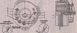
But since it is not so easy to find this device today, we will make do with improvised means. Non-contact ignition is configured by adjusting and setting the gap of the distributor contacts. An equally important nuance is the correct setting of the moment of sparking. Diagram and designation of parts of the IZH distributor
If your IZH Planet 3 is equipped with a single-cylinder internal combustion engine with a G-36 M generator device, then in this case the procedure for setting the gap is carried out by turning the eccentric, marked in the diagram with the number 1. In this case, bolt 2 according to the diagram must be loosened, and the eccentric itself is turned or right or left. Before setting the BSZ on products from the IZHMASH plant, the crankshaft must be turned. It rotates until the moment of greatest divergence of contacts occurs. It is in this position that the ignition of the IZH Planet 5 is adjusted - you need to ensure that the maximum gap on the contacts is around 0.35-0.45 mm.
According to experts, the ignition system should be adjusted with the cylinder head removed. In this case, the piston itself must be located in a position where it does not reach the dead center; to find out what the clearance should be in this case, you need to use the instruction book. For example, in versions 3 this parameter should be 3.5-4 mm, in Planets 4 - from 3 to 3.5 mm, and in Sports versions - from 3.5 to 3.8 mm. It is in this position that the spark will appear. The adjustment procedure in this case is performed by turning the interrupter assembly, while the bolts marked in the diagram as number 10 must be loosened.
Assembly diagram for IL
, in particular, setting the gaps between the contacts of the interrupting device should be done in the following order:
- First of all, the crankshaft is turned by the kick starter.
- One of the interrupting elements is set to the contact opening position. In this case, the bolt marked number 4 in the diagram must be loosened.
- Next, using the eccentric number 3, the gap is set; this figure should be from 0.4 to 0.6 mm. After this, the same actions are carried out with the second pair of contacts.
It should be noted that the entire procedure must be carried out with the candles unscrewed. When you place the dipstick in the corresponding hole for the spark plug in the right cylinder, you need to turn the crankshaft with the kick starter. You need to find the top dead center and having found it, you should make several marks on the dipstick - one of the marks should be placed at the level of the hole, and the other should be located slightly higher - about 2-3 mm. After this, the crankshaft must continue to be turned, this is done until the upper mark reaches the position in which the first mark at top dead center was set (video author - Garage in the USSR).
Setting up the Izh Planet ignition
In this position, the elements of the interrupter assembly, which is located on the lower surface, will begin to open. It should be noted that the procedure for setting the contact opening is done by turning the base, but to do this you need to loosen the bolts numbered 2 and 7. And when you can make the adjustment correctly, these screws will need to be tightened. As for directly determining the moment of rupture, it can be detected thanks to a light bulb, which must be connected in advance to the body ground and the distributor terminal.
After the torque on the right cylinder has been set, the same procedure is performed in a similar way only on the left cylinder. In general, the situation is similar, only in this case it is not the lower, but the upper base that rotates, and in this case, bolts 1 and 7 should be loosened.
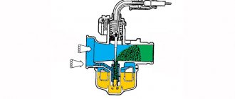
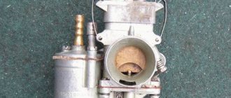
Adjusting the K-68 carburetor on the IZH Planet-5 motorcycle
The K-68I carburetor was installed on the Izh Planet-5 motorcycle more often than others. With proper setup and proper care, the motorcycle starts quickly, runs smoothly and without complaints.
To adjust the K-68I carburetor you will need a flat-head screwdriver, pliers, and a ruler. For clarity and ease of adjustment, use the K-68 carburetor diagram.
Algorithm for adjusting the Izh Planeta-5 carburetor:
- The first step is to check the fuel level in the float chamber. Unscrew the camera cover bolts with a screwdriver and remove it. Turn the carburetor over and use a ruler to measure the distance from the carburetor body to the top edge of the floats. It should be 26 ± 5 mm. If the parameters deviate, the tongue of the floats is bent in the appropriate direction using pliers. At the same time, in no case should the parallelism of the floats be disrupted.
- Set a gap of 2 mm between the throttle valve and the bottom of the mixing chamber by adjusting screw 11. Then check the position of the throttle needle. The required needle position is the middle groove. The remaining grooves are made to move the needle lock and adjust the appropriate fuel quality depending on climatic conditions.
- After all the above steps, we proceed to the most important stage - setting the idle speed. The idle quality adjusting screw 15 (located vertically on the left side of the carburetor) is screwed in until it stops, and then unscrewed 1-1.5 turns. Start the engine and warm up for 5 minutes. Using the mixture quantity adjustment screw 11 (located horizontally on the left side of the carburetor), we set the minimum stable engine speed. At the same time, slowly unscrew screw 15 until the engine speed stops increasing. It is the moment of reducing the crankshaft speed that will be optimal for determining the position of the adjusting screw 15. We again reduce the engine speed with screw 11 and unscrewing screw 15, we find a new optimal position of the throttle valve. This operation must be repeated until the minimum, but at the same time stable, engine crankshaft speed is established.
- By sharply turning the throttle lever at idle, we check the correctness of the adjustment (the quality of the mixture). If, when the throttle is opened sharply, the engine stalls or picks up speed poorly, screw 15 needs to be tightened a little, thereby enriching the mixture. If the engine stalls when the throttle is closed, screw 15 should be unscrewed slightly.
- You can also check the correctness of the adjustment by the color of the central insulator of the spark plug. After adjusting the carburetor, drive a motorcycle for a distance of 5-10 km and remove the spark plugs from the cylinder head. Dark carbon deposits indicate that the mixture is too rich. A light color (whitish or sandy) indicates that the mixture is poor. The normal recommended candle color is brown or brick.
- It is also worth remembering that the free play of the throttle cable is 1-3 mm. If it is not there, the throttle adjustment will be incorrect. The free play is set by adjusting a special bolt located under cap 18.
Recovery process
When the euphoria of the purchase wears off, a lot of questions arise regarding its repair and restoration with your own hands.
DIY BSZ on IZH Planet 5
The main task of the new owners:
- Restore the electrical system - and there are no particular problems with this, since the electrical wiring of IZ Jupiter 2 and Planet of the second and third generations is identical and interchangeable;
- Starting the engine is a more difficult task due to the need to overhaul the power unit and the availability of spare parts;
- Return the motorcycle to its original appearance. It is also quite complex and, perhaps, the most painstaking work of the entire project.
The video below shows the restored models.
Izh Planeta 2
Factory layout for several generations of motorcycles
- Whether to switch to contactless ignition or change the voltage from 6 to 12V is up to you to decide.
- If you have such a desire, and you manage to get your hands on a native Izhevsk generator 281.3701, then the replacement process will be much easier.
- The publication IZ Jupiter 3 wiring diagram will familiarize you with the details of the alteration.
central locking
Let's consider the process of restoring the central lock, since in most surviving models it is faulty.
Appearance of the headlights and controls of IZH Planet 2
The difficulty is that finding the original lock is very difficult, almost impossible. Moreover, at 6V, since later the Izhevsk Motor Plant transferred all subsequent models to 12-volt equipment.
This is what the filling of the original 6V ignition switch looks like
Therefore, many motorcycle owners adapt parts from later versions of Planets and Jupiters.
The difficulty of installation in this case is as follows:
- Uncertainty about whether the lock will work;
- How to properly connect wires.
Wiring diagram for IZH Planet 2 to the lock
Headlight
Many owners do not attach importance to adjusting the head light, believing that a working light bulb and intact glass are enough for “driving” during daylight hours.
Using this scheme it will be easy to connect all consumers
Correct ignition settings for Izh Jupiter 5
In fact, this is not so, and adjusting the light is not only desirable, but also mandatory, especially since it can be easily done independently, spending no more than half an hour of personal time on it.
Scheme for adjusting the angle of luminous flux
Setting the appropriate options
Setting up the BSZ on Izh Jupiter 5 also requires special attention. The ignition is turned on with the tachometer connected. After thirty seconds, indicators of 3000, 4000, 5000 rpm should appear on the device panel. If they are present, then the switch is working correctly.
In other cases, you should pay attention to previously grounded candles. We insert a screwdriver into the hall connector, and then pull it out
A spark should appear on the spark plugs. If it was not possible to cause a spark using the steps described above, then the reason for the incorrect operation is incorrect connections.
The setup looks like this. The dial indicator is unscrewed and the cylinder piston is adjusted. Having connected the voltmeter to the second and third connectors, you need to start rotating the modulator axis. After a jump from 7 to 0.1 volts is detected, the modulator must be secured with a nut. Usually the required advance angle is set.
The test run should be successful if you install the components yourself according to the instructions. Now you can use BSZ.
The main problem with the Izh Jupiter motorcycle engine is the standard contact ignition system. Any owner of Jupiter sooner or later faces the problem of failure of one of the cylinders due to a change in the gap in the contacts or failure of the capacitor. Adjustment helps, but usually not for long. This problem can be radically solved by installing a contactless ignition system on a motorcycle.
Single-channel BSZ.
There are probably many options for BSZ design, but we won’t consider them all. Let's focus on the simplest, and probably the most common option in our country. There is no motorcycle market or motorcycle store nearby where you can buy a factory-made BSZ, and there is no turner with a machine nearby either. We will proceed from this.
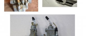
Minimum set for installation
But we can’t do without a minimum set, so before you start work, you need to stock up on the following components, which are sold in any auto shop or car market in our country:
Ignition circuit Izh Planet 4 12 volts. Izh Planet bike of the fifth model: what should you know about its wiring? explanations for the diagram
1. Switch from VAZ 2108
2. Hall sensor from VAZ 2108
3. Set of wires for BSZ from VAZ 2107 (from distributor (Hall sensor) to switch)
4. Two-terminal ignition coil (from an Oka or Gazelle car with a ZMZ 406 engine)
5. Two automotive silicone high-voltage wires of the required length with caps for spark plugs (you can buy a kit for a VAZ and take it from there, you can simply find used wires, after first making sure they are working)
Next, in addition to the components, we will need a small flat piece of sheet steel 1-1.2 mm thick to make a modulator and a plate for the Hall sensor. I warn you right away that stainless steel or non-ferrous metals are not suitable for the manufacture of the modulator, since they are not magnetic materials. To make a plate for the Hall sensor, you can use any material of sufficient strength.
Tools you may need are a drill with drills, files, a chisel, a hammer and other tools that, as a rule, are found in any garage.
Rework process
We dismantle the old ignition system. We remove the plate with contacts, capacitors, ignition coils with high-voltage wires from the motorcycle. We install the switch in the right glove compartment.
We attach the ignition coil to the frame under the tank. We connect the wiring connector to the switch, connect the black ground wire from the connector to ground. We connect the wire from terminal No. 1 of the switch connector to one of the coil terminals. We connect the second terminal of the coil to the old wiring, to the wire to which “+12V” is supplied when the ignition is turned on. In the old wiring, this wire connected both ignition coils. From it we pull an additional “+12V” wire to the switch, which we connect to the 4th wire in the connector. We carefully isolate everything. We insert the wire with the connector to the Hall sensor into the cavity of the generator.
You can check the functionality of the system. We connect the Hall sensor to its connector, connect the high-voltage wires to the coil and to the spark plugs. We provide reliable weight to the candles. Turn on the ignition and pass a metal object (you can use a flat screwdriver) through the Hall sensor slot. The spark plugs should spark. The scheme is working. (If there is no spark, then something is connected incorrectly and everything needs to be checked again.) Now it remains to supply a spark at the right time to the cylinders, for this:
Required Parts
In order for the ignition system to work correctly, a number of auxiliary parts are required. They are listed below:
- Switch for BSZ VAZ cars. You should not choose exclusively from the low price segment. The Astro switch has a lot of positive reviews;
- Hall Sensor. The best option for Jupiter 5 is a similar manufacturer VAZ. By purchasing it in branded packaging, you protect yourself from counterfeits;
- Ignition coil with two terminals. You should choose between the gazelle engine number 406 or Oka with an electronic ignition system;
- A pair of silicone armor wires with rubber caps;
- The modulator is a butterfly-shaped plate made of iron.
Modulator
The most difficult stage is the production of the modulator
It is important to maintain the required shape. The more reliably the required dimensions are observed, the lower the likelihood of problems occurring after implementing the system, that is, there will be no need to adjust it using a file
The ignition timing must match on any cylinder used.
The bolt hole must be located in the middle. Otherwise, the engine operation will not be synchronized. It is also recommended to check the integrity of the crankshaft bearings. If you find defects, you should immediately replace it.
The contact ignition is not able to work normally if the bearings are damaged. The thickness of the part should not exceed one and a half millimeters. If it is thin, it will not be possible to avoid deformation, and if it is thick, it will come into contact with the surface of the hall sensor housing.
To create the plate, it is allowed to use any material except steel. Aluminum and others should not be used as they are not magnetic. The drawing that must be followed can be found in the public domain. The presented diagram will be useful to those people who decide to modernize the vehicle ignition device. Below are methods for installing electrical ignition devices in Jupiter.
It must be turned by a professional turner. He will make a simple disk and draw on it the markings of elementary distances between the corners. Then, in accordance with it, you will cut out the necessary sectors at home. The cost of the modulator is seventy rubles.
It is not advisable to use an ordinary plate, since its width is less than twelve millimeters. This will not be enough to fully accumulate the energy resource in the coil. Of course, it can be installed, but achieving four thousand revolutions per minute will become impossible.
In addition to the above you will need:
- A stud with an applied thread of seven millimeters, pitch 1, as well as a pair of nuts with washers of the corresponding parameters. The priority material for these components is brass. This is explained by the least magnetization of the plate from the generator rotor. If you use a standard bolt, then difficulties may arise with the introduction of ignition. The bolt tends to follow the modulator as it is tightened. However, it is necessary to observe the leading indicator, maintain the same position of the rotor and modulator, and tighten the bolt. It is advisable to use a pin, since many are not able to perform all the necessary actions in total;
- A set of wires with connectors for ignition without contact from VAZ. This part can be purchased or made with your own hands.
Improving the standard system
The ignition system can be improved in other ways. To do this, you need to identify what problems there are with the wiring. They can occur in the primary circuit between the coil and the 12V battery or due to operating conditions. A visual inspection of the primary circuit can reveal problems with connections, contacts and the ignition switch.
But when dirt and dust get into the circuit, the resistance at the contact points increases, which entails a decrease in voltage from 12 Volts to 7-8 Volts. This voltage is not enough for a powerful discharge to appear in the secondary winding of the coil. As a result, a charge of less than 12 V appears on the spark plug, which poorly ignites the combustible mixture in the cylinders. Burnt contacts, oily spark plugs and batteries with a charge of less than 12 V further worsen sparking.
The following measures help solve these problems:
- The plug connectors are removed and each wire is soldered using traditional soldering and then insulated.
- An additional toggle switch is installed that turns off all consumers when the engine starts. Thus, the coils are supplied with 12 volt voltage from the battery (diagram 1).
- Remake the ignition switch (IZ) (diagram 2). You need to take a wire and solder one end of it to the connector of lock 4, which is free, and the other to the positive terminal of the coil. The standard wire should be re-soldered from terminal 5 to terminal 6. After turning on this position of the key, power is supplied from the battery to the primary circuit according to a simplified scheme.
Wiring diagram IZ Jupiter 3, legends of the domestic motorcycle industry
We would like to note right away that motorcycles of the IZH family were the most democratic and affordable form of transport in the 80s, which gave freedom of movement to many young men and adult men. In those years there was no Internet or cable TV, so wiping your pants on the couch was unfashionable. But the wiring diagram for the IZH Jupiter 3 was read to the gills by these same young men, which many adult aunts and uncles recall with nostalgia today. Legend in factory configuration
Model features
Therefore, even today, enthusiasts retrieve famous motorcycles from dusty sheds and garages, restore them to their original form and, as before, give the spirit of freedom to their owners. Taking a motorcycle out of the woodshed, there is hope that it will return to service again
What is especially pleasing is the interest of modern youth in domestic technology. This article is intended for them and their parents who had the opportunity to drive Izhaks, Jupiters and Planets.
Electrical diagram
The IZH Jupiter 3 model appeared as an improved example of the previously produced IZH Jupiter 2. For the first time in domestic practice, a motorcycle received turn signals, and therefore the wiring diagram of the IZH Jupiter 3 has undergone changes.
In particular:
- There was a separate cable running under the gas tank and seat to the rear turn signals;
- For the model with a side trailer, a second cable was laid and attached to the stroller frame.
The new model is based on the proven electrical circuit of its predecessor.
The photo above also shows the wiring for the IZ Jupiter 3 in the version with a sidecar.
They asked from her:
- Lamp (yellow) for trailer brake lights (indicated as 2a in the diagram);
- Lamp (red) for the rear marker light of a trailer (3a);
- Right direction indicator on the trailer fender (11);
- Trailer front marker light (white) (17).
One can argue for a long time about the quality of products of the domestic motorcycle industry, but a motorcycle in capable hands required only preventive maintenance and adjustment. And the era of shortages forced owners to show miracles of ingenuity, modifying unreliable components and assemblies of their two-wheeled horses.
Self-improvement
Many were not satisfied with the capricious ignition of the motorcycle (see the article wiring diagram for IZH Planet 3), so the wiring diagram for IZH Jupiter 3 was often changed from 6 to 12 volt. This was facilitated by the appearance of the 281.3701 generator produced by the Izhevsk Motor Plant, which was much better and more reliable than the standard G36M7. Those owners who were not able to get it had to upgrade the existing one.
For this:
- A steel adapter plate was machined, allowing 12 internals to be installed in the generator;
- The right engine cover was purchased or exchanged from older models Jupiter 5 or Planet 5.
Exterior view of modified crankcase with steel plate
Motorcycle service
Unlike other models, both domestic and foreign (see the article for the wiring diagram of the Delta moped), the IZH Jupiter 3 is distinguished by its enviable survivability.
Here are a few instructions for resuscitating a motorcycle that has stood motionless:
- It is enough to replace or clean the candles yourself;
- Adjust the ignition;
- Replace high-voltage wires from the coils with spark plugs;
- Change the engine oil;
- Install a new battery or charge the existing one.
Modern scheme, more understandable to the younger generation
And it will start and drive. And this is its distinctive feature, which is well known to the generation of the 80s. You can restore the old paintwork, reupholster the seat, or polish the chrome parts to a shine later, the main thing is its durability.
In the video below you can get acquainted with the features of this model. It should be noted that the cost of restoration is quite affordable for most, and the difficulty lies only in the lack of spare parts and the need to modify those found from other models.
conclusions
If you have an IZH Jupiter 3 collecting dust in your barn or garage, do not rush to sell it for scrap. Bringing it back to life will give you a feeling of youth and give you the opportunity to travel across the expanses of the country again. Even if it’s just a fishing trip or a picnic, the main thing is that you will save a real legend.
Motorcycle Izh Jupiter 5 - technical specifications and photos
Soviet motorcycles today are considered valuable transport, because back then they produced really high-quality and fast equipment. The Izh Jupiter 5 motorcycle is considered one of these legends of the USSR.
The Izhevsk plant produced several models, including Planet 5 and others. But Jupiter 5 was remembered primarily for its unpretentiousness on roads and maneuverability. With its small dimensions, the model was able to achieve low fuel consumption.
pros
- powerful engine;
- sharp at start;
- spare parts for Izh Jupiter 5 are inexpensive and available;
- soft suspension;
- low cost;
- has 2 cylinders.
Minuses
- weak front fork;
- requires good ignition settings;
- high fuel consumption;
- Motorcycles today require frequent repairs.
Technical characteristics of Izh Jupiter 5
The design of the motorcycle was created in such a way that in the end Izh could ride equally comfortably both on the highway and on uneven roads. Unlike its brother IZH Planet 5, this model had 2 cylinders, which means more power. Also, the owner of the motorcycle could start the engine more easily, which is explained by the absence of the leg returning when started.
Review
Classic transport has always been valued since the USSR, and 20 years ago Jupiter 5 was one of the best.
Today, most riders ride foreign fast motorcycles, but occasionally you can meet a former legend of the 80s and 90s.
In those years, only his brother Planet 5 competed with Jupiter, but he could not compare with the motorcycle in terms of characteristics. Their main difference was the difference in cylinders, and therefore power.
If we continue to compare these two competitors, we can highlight the fact that both models had almost the same data.
For example, they had one tubular frame, and a special subframe was installed to better secure the rear wheel.
In general, the entire design of Jupiter 5 was quite standard and simple, the engine was attached to the frame, the fuel tank was located above, and the headlight and dashboard were installed on the steering wheel.
There were also 2 exhaust pipes installed that ran through the entire motorcycle. Sometimes the pipes got hot and could cause a burn, but the manufacturer installed them below the footpegs to keep the passenger as safe as possible.
Even the first models of the Izh Jupiter 5 motorcycle had simple drum brakes with a mechanical drive, but subsequent modifications received a front disc brake with a hydraulic drive.
Motorcycle appearance
When the Jupiter 5 model came out, its design was already well-known, because it was inherited from the Jupiter 4 motorcycle. But soon the Izh Planet 5 appeared on sale, and the developers saw that they could borrow several design elements.
The first modification had a square-shaped dashboard, which consisted of several indicators, an ignition switch and a speedometer. But soon its appearance was redesigned, and instead of one dashboard there were two. On the first part they placed warning lamps, and on the second part they decided to put a speedometer.
The design of the fuel tank has also been slightly redesigned, with rubber pads on the knees and the shape of the tank itself has become slightly different. Accordingly, in the new modifications of the Moto Izh Jupiter 5, it received a different, longer seat that ended at the brake light. This innovation is still considered stylish and modern.
Being a workhorse, the motorcycle had a fairly sporty appearance and excellent top speed. With a power of 25 hp. the motorcycle could accelerate to 120 km/h.
This is a completely standard indicator, because another representative of the Dnepr could give a maximum speed of 110 km/h. In severe frosts down to 30 degrees, the unit started up perfectly, which cannot be said about the current new products.
Unfortunately, many owners complain of frequent engine breakdowns due to their long lifespan.
Price
Today, a motorcycle of this model is not so difficult to find; in Soviet times it was bought in large quantities, so today you just need to find out how much the Izh Jupiter 5 costs. Of course, the price depends on the condition, because over such a long period many parts could become faulty.
Even during the release of the Izh Jupiter 5 motorcycle, its price was quite high - 1,050 rubles. But this did not stop buyers; they wanted a comfortable and fast motorcycle, which was the best then. But still, compared to other motorcycles, this model had a relatively low price. For example, then new Ural motorcycles had a price of 1,870 rubles.
If you want to buy a legend of the USSR today, be prepared to pay 55,000 rubles for a new motorcycle. Yes, they are still being reliably produced. If this price is too high for you, buy a used model - its price ranges from 5 to 40 thousand rubles.
Maintenance Features
Often during operation it is necessary to correctly set the gap between the contacts of the breaker. To do this, you need tools and a diagram to see which elements need to be dismantled.
The algorithm of actions is as follows:
- place the motorcycle on the stand;
- turn on neutral;
- unscrew the spark plug from the cylinder;
- remove the engine crankcase cover;
- turn the crankshaft until the contacts are as open as possible;
- using a screwdriver, loosen the locking screw;
- using a special feeler gauge, set the gap to 0.35-0.45 mm and fix it with a screw;
- we collect everything in reverse sequence;
- turn on the ignition and start the engine. Its stable operation at idle indicates that the adjustment has been correctly performed.
In general, all the wiring of IZH Planet 5 is very easy to do with your own hands.
The need for such work often arises when operating a motorcycle:
- in wet weather, driving in the rain for a long time (oxidation or dampness of electrical contacts);
- when traveling over rough terrain, replete with vegetation and bushes (mechanical damage to wiring);
- when used in winter (snow and slush stick to the wires and can damage them).
Often the sound signal suffers during operation. Its malfunctions manifest themselves in the form of deterioration in sound quality.
To restore its functionality, you must perform the following procedure:
- loosen the locknut using an open-end wrench;
- turn on the ignition;
- press the button to turn on the sound signal;
- use a screwdriver to adjust the tone;
- repeat the procedure until we get a clear and loud sound;
- tighten the control nut.
Conclusions: we are confident that this article will help you in servicing motorcycles of the IZH family (see also the article about). Both the attached diagrams and description will help you avoid making mistakes during operation.
While easily fixing mechanical failures, motorcyclists experience difficulties if the electrics fail. It’s completely in vain, the wiring diagram of the planet Izh 5 is not complicated, it’s easy to figure out.
There is no need to have special stands and equipment for repairs. A minimum knowledge of electrical engineering and a simple avometer (tester) is enough; even often you can get by with just a test lamp.
We will tell you in more detail about the main electrical wiring components and possible malfunctions. The Izh Planet wiring diagram makes it easy to find a broken wire or damaged insulation (for example, a bad contact always gets hot).
In this case, we look to see if there is a spark at the coil output and at the output at the spark plug contact. Let's take a closer look at the main wiring components of the Izh Planet.
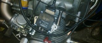
Switch Voskhod - electronic KET-1
The electronic switch KET-1 is designed to work in the ignition system complete with the G-427 generator and the B-300B high-voltage transformer. Allows you to obtain a secondary voltage of up to 18 kV, at a generator rotor speed of 250 to 7500 rpm. The switch is installed in the right toolbox. The base of the commutator is connected to the ground of the motorcycle. If the switch fails, it can be disassembled and repaired
The electronic switch has three output terminals with letter markings on the body >, > and >. The ground terminal is the base of the switch.
Maintaining the switch during operation comes down mainly to tightening the threaded connections, while avoiding stripping the threads. It is necessary to protect the switch from moisture getting inside it and onto the terminals from sudden shocks and exposure to high temperatures. You should also systematically check the reliability of the electrical connection of the switch base with >, because If this condition is violated, sparking on the spark plug stops.
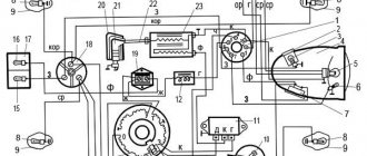
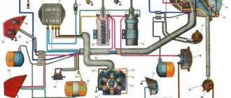
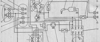
Electrical circuit of the Voskhod motorcycle
Central switch. 2. speedometer. 3. Speedometer light. 4. Headlight. 5. Headlight lamp. 6. City driving lamp. 7. Sound signal. 8. Direction indicator lamp. 9. Direction indicators. 10. Direction indicator switch. 11. Electronic switch. (D - sensor terminal, K - ignition coil terminal, G - generator terminal.) 12. Throttle. 13. Relay breaker. 14. Generator. 15. License plate lamp. 16. Brake signal lamp. 17. Rear light. 18. Wire connection block. 19. Brake light switch. 20. Shielded spark plug cap. 21. Spark plug. 22. High voltage wire. 23. Ignition coil. 24. Light switch.
Wire colors: sn. - blue, cf. - gray, g. - blue, g. - yellow, h. - green, k. - red, kor. - brown, op. - orange, f. - violet, h. - black.
The generator is good, but it needs to be rewound to 12V, otherwise the wiring will have to be redone a lot and the battery will not be able to be made into the lighting circuit; all the lamps except the neutral lamp and the 12V control lamp are easier to find than original ones. The faceplate was made according to drawings by Dmitry67:
The generator flywheel was not mounted as in the article, but as it should be - on a key. Of course, the rotor is 3 millimeters deeper than it should be, but everything works as it should
Article - “Does the Planet Need a Battery?” - have already been posted. This is right. It all started with this article for the majority of current users of such modifications.
However, there were earlier versions. I'll post one more to complete the collection. From the book of Boris Fedorovich Demchenko »
There are some mistakes there.
I converted several IZh motorcycles to Voshodov ignition (IZH 56, IZH P 3, IZH P 5, IZH PS, IZH Yu 3, IZH Yu 5.)
In the process of this work, optimized drawings of adapters were developed. The preferred material is alloy D 16. It does not rust - it is easy to process and holds the thread normally. If there are no suitable aluminum alloys, plain steel will do. The only negative is that it can rust. I don’t recommend stainless steel - it’s difficult to process it later on site. Drilling is also vicious. I tried to make one adapter from hot stainless steel - I did it but cursed everything.
Briefly speaking. The installation of the IZH generator 6 volt and 12 volt is different. Accordingly, different adapters are needed, depending on the motor model.
Drawings of blanks for a turner:
During manufacturing, it is advisable to sharpen the adapter from one installation. That is, at the end of processing it should be like a ready-made adapter - attached with the narrow end to the blank. And then they cut it off from the blank and trim the cut edge. This will create a part without compromising the wall thickness.
A little later there will be a continuation. This is not all I wanted to write yet.
Tuning the Izh motorcycle. BSZ on Izh Jupiter
The main problem with the Izh Jupiter motorcycle engine is the standard contact ignition system. Any owner of Jupiter sooner or later faces the problem of failure of one of the cylinders due to a change in the gap in the contacts or failure of the capacitor. Adjustment helps, but usually not for long. This problem can be radically solved by installing a contactless ignition system on a motorcycle.
Single-channel BSZ.
There are probably many options for BSZ design, but we won’t consider them all. Let's focus on the simplest, and probably the most common option in our country. There is no motorcycle market or motorcycle store nearby where you can buy a factory-made BSZ, and there is no turner with a machine nearby either. We will proceed from this.
Minimum set for installation
But we can’t do without a minimum set, so before you start work, you need to stock up on the following components, which are sold in any auto shop or car market in our country:
1. Switch from VAZ 2108
2. Hall sensor from VAZ 2108
3. Set of wires for BSZ from VAZ 2107 (from distributor (Hall sensor) to switch)
4. Two-terminal ignition coil (from an Oka or Gazelle car with a ZMZ 406 engine)
5. Two automotive silicone high-voltage wires of the required length with caps for spark plugs (you can buy a kit for a VAZ and take it from there, you can simply find used wires, after first making sure they are working)
Next, in addition to the components, we will need a small flat piece of sheet steel 1-1.2 mm thick to make a modulator and a plate for the Hall sensor. I warn you right away that stainless steel or non-ferrous metals are not suitable for the manufacture of the modulator, since they are not magnetic materials. To make a plate for the Hall sensor, you can use any material of sufficient strength.
Tools you may need are a drill with drills, files, a chisel, a hammer and other tools that, as a rule, are found in any garage.
Rework process
We dismantle the old ignition system. We remove the plate with contacts, capacitors, ignition coils with high-voltage wires from the motorcycle. We install the switch in the right glove compartment.
We attach the ignition coil to the frame under the tank. We connect the wiring connector to the switch, connect the black ground wire from the connector to ground. We connect the wire from terminal No. 1 of the switch connector to one of the coil terminals. We connect the second terminal of the coil to the old wiring, to the wire to which “+12V” is supplied when the ignition is turned on. In the old wiring, this wire connected both ignition coils. From it we pull an additional “+12V” wire to the switch, which we connect to the 4th wire in the connector. We carefully isolate everything. We insert the wire with the connector to the Hall sensor into the cavity of the generator.
You can check the functionality of the system. We connect the Hall sensor to its connector, connect the high-voltage wires to the coil and to the spark plugs. We provide reliable weight to the candles. Turn on the ignition and pass a metal object (you can use a flat screwdriver) through the Hall sensor slot. The spark plugs should spark. The scheme is working. (If there is no spark, then something is connected incorrectly and everything needs to be checked again.) Now it remains to supply a spark at the right time to the cylinders, for this:
We make a plate for mounting the Hall sensor.
There are no requirements for the shape of the plate as such. It must ensure that the Hall sensor is mounted at a certain distance from the armature axis.
The approximate markings of the central hole and cutouts for the mounting screws to the generator can be copied from the old, removed contact mounting plate. We mark the Hall sensor mount in such a way that the distance to the rear wall of the sensor through the magnet slot from the center of the armature is around 60-65 mm. You can machine additional grooves in the plate being manufactured in the attachment to the generator to ensure slight rotation of the plate around its axis (to facilitate setting the ignition timing), but you don’t have to do this, but simply attach the plate tightly to the generator. We drill, sharpen, adjust in place, install the plate with the Hall sensor on the generator.
Setting up the ignition of IZH Planet 5
Published May 24, 2018
I apologize if something is not clear. Write me and I will answer all your questions. I often see that such questions as “Ignition” are very relevant, alas, there are very few video reviews. So, I decided to help in any way I could)
Here is an excellent article about setting up the ignition https://www.motovelosport.ru/cat/izh_d.
PS Subscribe, there will be more videos soon. Next review and setup of the “K62I Carburetor”
Thank you very much for the video
Somehow it worked strangely for you, but everything is clear.
It's a pity that you only have one video.
thank you very much for the video. works well))
Do your fog lights work and make a video about installing them.
for those who don’t know it will do))
Thank you, it works. And he almost doesn’t kick)
the arcs are welded to the frame. tin.
ha, I’m 17, I’ve never watched or read anything, and I learned this myself through trial and error. This is my first time watching a video like this
Even though I learned this myself, I still give it a “like” Well done guys!
Vlad, I have a question. I tried to set up the ignition as in your video, but I ran into a problem. In general, the light comes on no matter what position the ignition caliper and cam itself are in. Closed, open, no use, it still burns. I set it up at random, spun it, the motorcycle started up, but it started sneezing from the carburetor. What to do?
what to do if the ignition seems to be turned on, I start it and the crankshaft first turns forward and then sharply back... I can’t solve the problem in any way
Regarding the TDC, how to set the TDC, I don’t understand something at all, and where exactly should I connect the +contact, I’m a beginner rider and that’s why I have such questions)))
You didn't explain it exactly enough. First, the breaker and its connections are adjusted to the maximum opening and a gap of approximately the thickness of two razors is set and adjusted with one bolt. And only after that the piston is brought 3.5 mm before the Top Dead Center and the ignition timing is set through the light bulb and tightened with two bolts
people and a spark can run on fists, such a good spark is as bright as a candle. You can also use the condenser. yaksho, why does the stench burn in me. I've already changed 2.
Guys, tell me the engine of the pislya overhaul repair, the ignition is on the light bulbs, a shat appeared in Bigunkov, and it affects the ignition.
Conder breaks through. I've been driving for many years and never had any complaints about it.
First, the gap between the cams is set from 0.3 to 0.4 mm (If memory serves) and then, as you show in the video
they wrapped you up, you'll understand
Either the microphone is like that or they set it up like crap
I do it as in the video, I can’t find on the generator when the light comes on (it just + constantly sparks and that’s it)
Guys, help me when starting it sneezes through the mufflers. WHAT COULD BE??
With such an ignition, the engine will not reach the maximum speed on the highway, you will feel it, you need to set it a little ahead so that it stops every ten times, it starts just as well and does not go back)))
on planet 4 I can’t adjust the TDC because there’s a spark plug on the side
How evil is the video of the ignition adjustment. no where on planet 4
the video is not complete.. you didn’t show how the eccentric (cam) opens the contact.. then there would be a complete tutorial)) correct it if it’s not difficult
I'm freaking out, light bulbs are crap, there are fewer problems to regulate on Jupiter than on the planet, but with a light bulb only children can adjust it
40% is wrong
https://www.youtube.com/watch?v=L3G7axG3nIg watch and subscribe
on the bracket the Conders are eternal if it is Savetky of course I have the ability to have a 92 year old planet on the generator and everything is marked with red paint for the ignition they have never been changed
But how to set the lead? How to rotate the platform?
Sorry, there was a question, I set the ignition (lowered the piston 3mm from top dead center and adjusted the gap on the contacts) and it began to kick back very hard, it hits every 3 or even 2 times when I try to start it, sometimes it hits even when the leg only slightly goes down, this happens a strong blow (is this normal or does it need to be reconfigured, I tried to do it a little later, it still hits) and the cam is from 6 volt Izh had to be sawed in another place to be chamfered (previously there was an ignition from Minsk and it never struck back, wasn’t it the same system, mskra in both cases strikes at the moment of advance)
Cheerful tuners, the light came on, tightened everything up and listen to how it works? Well done.
Hello guys, I would like to find a Planet 4.5 motorcycle to take home, I am from Tajikistan and I have an old one at home from different planet Jupiter, we use it for agricultural work, we repair it almost every year, but it is very tired. I want to pick it up from Russia here you can find almost none left, but they gave me scrap metal, if I find it, I’ll pick it up, I’ll hand it over to the guys here, they load it on a truck for 1 kg 50 rubles. I’m in Moscow, sorry, I’ve blabbed so much like this.
For contact 89991147194 89250205527 Zh Botir thank you
how to make a light for a headlight, I redid everything, nothing works
Source
How to install electronic ignition on IZ Jupiter 5
To improve their motorcycle, many drivers install an electronic ignition system on it. Which in turn has a positive effect on the operation of the productive element. Its dynamics are improved, the unit operates much smoother without interruptions. At idle speed, changes for the better will be immediately visible. Also, the converter element will respond better after applying gas to the handle. And starting the engine will not be difficult even with a weak battery charge. That is why most drivers are so willing to purchase electronic ignition for IZ Jupiter 5.
Installation process
It won’t take much time to replace the ignition, maybe a day. The necessary parts can be removed from the Oka vehicle. Electronic ignition is a set of wires, a generator, a two-terminal ignition coil, a Hall sensor and a switch.
There is no need to make any changes directly to the generator itself. You just need to remove the cams and where there is space, attach the Hall sensor
It is very important that the modulator plate passes through the slots of the sensor itself. Thanks to the modulator plate, smooth ignition operation is ensured
Unstable sparking is often caused by an incorrect design of the so-called magnetic flux contactor. In this case, you need to carefully study its placement in relation to the sensor. Overlapping of the magnetic circuit or magnet is unacceptable in the open state of the contactor, while the closed state of the contactor implies complete overlap of these two elements. If this is not the case, then most likely the sensor will emit weak signals to the switch. As a result, unstable engine operation will be observed.
To make a modulator you will need a steel disk with a cutout of 0.8-1 mm
It is important to maintain a ratio of closed to open periods of 2:1. The angle of the cutout in the modulator depends on the type of main power unit
If the main power unit is 1-cylinder, then the angle is 120 degrees. On 2-cylinder engines, an angle of 60 degrees is maintained. The width of the cutout starts from 11 mm and more, but not less. You should also know: a spark occurs when the modulator “opens” the sensor. This is very important when setting the ignition timing.
Before installing electronic ignition on the IZH Jupiter 5 motorcycle, check that there are no large plays on the generator shaft. If they are, you should replace the generator bearings in order to get rid of the “bumpiness”.
How to set the ignition?
When setting up the ignition, problems often arise with setting the signal advance angle. A voltmeter will help fix this problem. Looking ahead, it should be said that a device designed for a minimum of 15 V and 10-50 kOhm (internal resistance) is ideal. A voltmeter is connected directly to the terminals. Next, you should bring the piston to the position at which sparking occurs. Then turn on the ignition and turn the modulator until the readings on the device change. You can track the charge on the spark plug by the voltage on the sensor, which should jump. This value is equal to tenths of a volt close to the on-board power supply of the equipment. As soon as the spark is “groped”, you need to fix the position of the modulator directly on the generator shaft. This is usually done with a bolted connection. When adjusting the ignition, constantly short-circuit the high-voltage wires to the frame of the unit. Otherwise, excessive load on the ignition cannot be avoided, which can lead to its failure.
how to set the ignition on Jupiter 5 | Topic author: Valentina
Features of self-adjustment of headlights on a gazelle
Diana According to the instructions.
Maria According to the instructions. Do you think someone wants to copy two printed sheets with instructions here for you?!
Vadim 2.6 mm to TDC opening of the contacts - the 12 V light bulb is on - this means the beginning. You need to connect the light bulb to the breaker contact and turn on the ignition and turn the crankshaft if I remember the key is 11
Alexandra First, you set the gap on the Liliya breakers; to do this, you turn the crankshaft by the head of the Egor rotor mounting bolt. You determine the maximum opening of the contacts and set the gap to 0.6-0.8mm. Next, you will need the Stepan bushing and wrench from the Anastasia motorcycle key set. You start adjusting the timing from the right cylinder Anatoly. You install Stanislav instead of the spark plug of the right cylinder!), lower the knob into it, and turning the same rotor bolt you find TDC Inna That's it, stop! By turning the sleeve to unscrew, you align the cut of the sleeve with the notch on the collar. Now you need to lower the piston two notches below TDC Anton You return to the breaker. You unscrew the three screws on the crossbar securing the breakers and move them slightly counterclockwise, the contact opens. If you have a battery, you can connect a 12v 1sv light bulb directly to the wire on Valery’s breaker; if you don’t have a battery, we use *tissue paper*. So the piston is lowered below TDC by two notches, i.e. 2.5 mm, if memory doesn’t fail us, don’t turn it anymore!) The moment has come to find the beginning of the breaker break, and the light bulb will tell you about it. By moving the lower joint of the breaker traverse clockwise, the light goes out and lights up counterclockwise. So you need to capture that moment when the light bulb lights up! Lights up, fix the lower screw of the traverse. The left cylinder is adjusted in the same way. Now about the tissue paper. It is used as an indicator to determine the beginning of a rupture. We install it between the contacts of the breaker and determine the beginning of the break by free movement when the traverse moves.
I always set Victor by eye) 2mm to top dead center with a feeler gauge, and the contact gap by eye is a third of a millimeter. It worked flawlessly, the cylinders did not fail, I set it up and drove it for a year until I sold it. but it depends on experience. try to set it in different ways, gain experience, then you can also set it by eye when you get better at it) in the days of Jupiters there was no Internet, they set the ignition by trial and error
Installing a contactless ignition system on Izh Jupiter-5 is a fairly current topic. When setting up a BSZ on Izh Jupiter-5 BSZ, it is necessary to take into account a number of nuances that can significantly affect the operation of the equipment used.
What advantages open up to users who decide to install electronic ignition on the Izh Jupiter are described below.
Most modern motorcycles are not equipped with cams, that is, breakers. Why did the manufacturer consider them unnecessary for currently sold models? The answer is quite simple. This system is not very reliable.
Many parts used in the system are sources of trouble. The most common ones are listed below:
- The ignition gaps change their original position while driving a few days after adjustment;
- A spark occurs every once in a while, since the contacts regularly burn out;
- Capacitors are constantly damaged;
- Low spark power;
- If you add two or three volts to the battery, it is quite difficult to start it. Such ignition is the reason for constant repairs while driving.
This is noticeable at idle. The speed of their passage has noticeably increased and the unnatural twitching has disappeared. The characteristic knocking sounds of iron components in the crankcase and accompanying detonations also disappeared. The handling of the Jupiter 5 motorcycle will improve simultaneously with the time it takes to gain speed.
Wiring diagram IZH Planet 5
Detailed color wiring diagram for motorcycle IZH Planet 5
Explanations for the diagram
The numbers on the electrical diagram correspond to the following elements:
- Light switch, dimensions/low.
- Light switch, direction indicators and horn buttons.
- Front turn signals.
- Instrument panel lighting.
- Indicator lamp for generator operation.
- Oil pump operation indicator.
- A light indicating the operation of the neutral gear in the gearbox.
- Direction indicators.
- High beam headlight indicator.
- Front parking light bulb.
- Headlight lamp.
- Sound signal.
- Hall Sensor.
- Generator.
- Egnition lock.
- Turn signal interrupter relay.
- Neutral gear warning lamp sensor.
- Block BPV 14-10.
- Switch.
- Battery.
- Fuse.
- Relay block.
- Ignition coil.
- Foot brake light sensor.
- Rear direction indicators.
- Rear light with lamps.
Description of the symbols for the terminals on the rectifier-regulator block BPV 14-10:
- –x1 — “minus” of the generator excitation winding;
- –x2 — “minus” of the battery (“ground”);
- x2 - “positive” wire to the control lamp of the instrument panel;
- x3 - “positive” wire to the panel indicator;
- x4, x5, x7 - phases of the stator winding;
- x8 - “plus” of the battery.
Electrical equipment IZH Planet 5
The motorcycle uses 12-volt electrical equipment. The electrical wiring of the IZH Planet 5 motorcycle is single-wire, the role of the negative wire is performed by a metal frame.
Among the main components are:
- Power supplies;
- Ignition system;
- Headlight;
- Side lighting and turns.
For reference: as is customary in auto and motorcycle construction, modification of components and assemblies allows you to reduce the cost of products. For consumers, the advantage is that the price is low and a number of parts are interchangeable.
Generator
The motorcycle is equipped with a three-phase alternating current generator with an electromagnetic excitation circuit.
The principle of its operation is as follows:
- Electric current from the windings located on the stator is supplied to the rectifier;
- It converts it to direct current;
- And supplies it to consumers through the ignition switch.
The instructions provided include the following items:
- Voltage regulator with rectifier BPV-14-10;
- Generator rotor;
- Generator stator with windings;
- Current collector brushes;
- Ignition system cam (battery);
- Ignition system contact unit
For reference: on three-phase generators of the IZH Planet 5 motorcycle, the windings are connected according to a “star” or “delta” circuit. The rectifier is installed as a separate unit, and the IZH Planet 5 electrical wiring is connected to it.
Headlight
Unlike European countries, where there is a requirement that motorcycles with permanent magnet generators must be equipped with a battery - since a motorcycle with a non-working engine must have side lights - there are no such restrictions in Russia (see also about the Ural motorcycle wiring diagram).
For reference: with such a generator, IZH Planet 5 did not need an external current source when starting the engine. Therefore, the battery was not included in the electrical equipment.
The head light circuit includes:
- headlight lamp (35W);
- blue indicator lamp (2W);
- headlight parking light (4W);
- rear brake light lamp (15W).
Control devices
The following control devices are installed on the motorcycle:
- speedometer with daily and total mileage counters;
- tachometer with indicator lamps for direction indicators and headlights;
- engine temperature indicator;
- voltmeter.