Installing a contactless ignition system on Izh Jupiter-5 is a fairly current topic. When setting up a BSZ on Izh Jupiter-5 BSZ, it is necessary to take into account a number of nuances that can significantly affect the operation of the equipment used.
What advantages open up to users who decide to install electronic ignition on the Izh Jupiter are described below.
Most modern motorcycles are not equipped with cams, that is, breakers. Why did the manufacturer consider them unnecessary for currently sold models? The answer is quite simple. This system is not very reliable.
Many parts used in the system are sources of trouble. The most common ones are listed below:
- The ignition gaps change their original position while driving a few days after adjustment;
- A spark occurs every once in a while, since the contacts regularly burn out;
- Capacitors are constantly damaged;
- Low spark power;
- If you add two or three volts to the battery, it is quite difficult to start it. Such ignition is the reason for constant repairs while driving.
Many people mistakenly believe that it is very difficult to implement BSZ Sovek on Izh Jupiter 5. As a rule, it takes more time to purchase the necessary spare parts than to install the BSZ on Izh. Of course, after implantation, performance changes significantly in the best direction.
This is noticeable at idle. The speed of their passage has noticeably increased and the unnatural twitching has disappeared. The characteristic knocking sounds of iron components in the crankcase and accompanying detonations also disappeared. The handling of the Jupiter 5 motorcycle will improve simultaneously with the time it takes to gain speed.
Generator
The heart is the generator (sometimes called a magneto, but they were never used on Izh Planet).
Three windings produce alternating current. For excitation, an additional coil is used instead of a permanent magnet. Therefore, it is impossible to jump start a motorcycle with a completely dead or missing battery. Possible breakdowns in this unit:
- It is checked by measuring their resistance of current-carrying conductors and insulation. If the generator is damaged, it will become noticeably hot.
- — the output voltage will differ significantly from the nominal level or be absent.
- Although the electrical circuit includes short circuit protection, it happens that the automation does not work and most often the output transistor burns out.
In what cases is ignition adjustment necessary?
During the operation of the vehicle, the owner faces many problems. The most serious failure is related to the engine. In order to spend significant funds on major repairs, it is necessary to monitor the technical condition of the motorcycle and carry out preventive work, including adjusting the valves and valves (video author - Hana Rulyu).
If you do not monitor the SZ, then the motorcycle engine may not reveal its full potential and will not work at full capacity. This can lead to a reduction in its service life. An ignition adjustment is necessary if the engine is running poorly, the muffler or carburetor is firing. True, before setting up the SZ, you should make sure that the cause of the malfunction is in it.
It happens that the flywheel bolt, which connects the two halves of the crankshaft, comes loose, begins to play and does not work well. Sometimes he even cuts the key.
Setting up the SZ may be necessary after repairing lock 5. The installation and connection itself are carried out according to the diagram.
Installation and configuration instructions
In IZH Planet motorcycles, be it version 3, 4 or 5, the ignition installation in accordance with the diagram must be carried out using the device that came with the motorcycle. But since it is not so easy to find this device today, we will make do with improvised means. Non-contact ignition is configured by adjusting and setting the gap of the distributor contacts. An equally important nuance is the correct setting of the moment of sparking.
If your IZH Planet 3 is equipped with a single-cylinder internal combustion engine with a G-36 M generator device, then in this case the procedure for setting the gap is carried out by turning the eccentric, marked in the diagram with the number 1. In this case, bolt 2 according to the diagram must be loosened, and the eccentric itself is turned or right or left. Before setting the BSZ on products from the IZHMASH plant, the crankshaft must be turned. It rotates until the moment of greatest divergence of contacts occurs. It is in this position that the ignition of the IZH Planet 5 is adjusted - you need to ensure that the maximum gap on the contacts is around 0.35-0.45 mm.
According to experts, the ignition system should be adjusted with the cylinder head removed. In this case, the piston itself must be located in a position where it does not reach the dead center; to find out what the clearance should be in this case, you need to use the instruction book. For example, in versions 3 this parameter should be 3.5-4 mm, in Planets 4 - from 3 to 3.5 mm, and in Sports versions - from 3.5 to 3.8 mm. It is in this position that the spark will appear. The adjustment procedure in this case is performed by turning the interrupter assembly, while the bolts marked in the diagram as number 10 must be loosened.
In particular, setting the gaps between the contacts of the interrupting device should be done in the following order:
- First of all, the crankshaft is turned by the kick starter.
- One of the interrupting elements is set to the contact opening position. In this case, the bolt marked number 4 in the diagram must be loosened.
- Next, using the eccentric number 3, the gap is set; this figure should be from 0.4 to 0.6 mm. After this, the same actions are carried out with the second pair of contacts.
It should be noted that the entire procedure must be carried out with the candles unscrewed. When you place the dipstick in the corresponding hole for the spark plug in the right cylinder, you need to turn the crankshaft with the kick starter. You need to find the top dead center and having found it, you should make several marks on the dipstick - one of the marks should be placed at the level of the hole, and the other should be located slightly higher - about 2-3 mm. After this, the crankshaft must continue to be turned, this is done until the upper mark reaches the position in which the first mark at top dead center was set (video author - Garage in the USSR).
In this position, the elements of the interrupter assembly, which is located on the lower surface, will begin to open. It should be noted that the procedure for setting the contact opening is done by turning the base, but to do this you need to loosen the bolts numbered 2 and 7. And when you can make the adjustment correctly, these screws will need to be tightened. As for directly determining the moment of rupture, it can be detected thanks to a light bulb, which must be connected in advance to the body ground and the distributor terminal.
After the torque on the right cylinder has been set, the same procedure is performed in a similar way only on the left cylinder. In general, the situation is similar, only in this case it is not the lower, but the upper base that rotates, and in this case, bolts 1 and 7 should be loosened.
Guide to setting up BSZ on a motorcycle
How to install electronic ignition on Izh Jupiter 5
To configure the system on a motorcycle, it is advisable to use devices with a scale of up to 15 volts and an internal resistance of up to 0 kOhm. Thanks to the electronic device, adjusting the unit will not take much time and effort. The terminals from the device must be connected to the Hall sensor. The procedure for setting up contact ignition without using auxiliary devices is shown in more detail in the video below (the author of the video is the Han Rulyu channel).
So, for proper tuning, place the cylinder piston in a position that provides the most optimal spark formation. Any cylinder can be used. Then the ignition is activated, and the modulator device must be turned in the direction of movement of the rotor with the crankshaft. Rotation is carried out until changes are visible on the voltmeter screen. At the moment when you can catch a spark, the position of the curtains should not be changed. As for the modulator device, it must be securely fastened to the generator shaft; a fastening screw is used for this.
During setup, you should in any case short-circuit the high-voltage circuits to the motor housing. This is done so that when using a short circuit, the system does not overload, which can ultimately lead to failure of the BSZ. In addition, the engine cannot be stopped when removing the spark plug caps.
After the adjustment is made, the performance of the system must be checked. If you place the cable being tested approximately 7-8 mm from the power unit and then try to start the engine, a spark should jump out. As you can see, in general, the procedure for setting up a node is not particularly complicated, but it requires care and the right approach, so the above recommendations are still worth considering. In addition, one should not forget about safety precautions, since incorrect actions can lead to a short circuit in the wiring and failure of the unit as a whole.
Required Parts
In order for the ignition system to work correctly, a number of auxiliary parts are required. They are listed below:
- Switch for BSZ VAZ cars. You should not choose exclusively from the low price segment. The Astro switch has a lot of positive reviews;
- Hall Sensor. The best option for Jupiter 5 is a similar manufacturer VAZ. By purchasing it in branded packaging, you protect yourself from counterfeits;
- Ignition coil with two terminals. You should choose between the gazelle engine number 406 or Oka with an electronic ignition system;
- A pair of silicone armor wires with rubber caps;
- The modulator is a butterfly-shaped plate made of iron.
Modulator
The most difficult stage is the production of the modulator
It is important to maintain the required shape. The more reliably the required dimensions are observed, the lower the likelihood of problems occurring after implementing the system, that is, there will be no need to adjust it using a file
The ignition timing must match on any cylinder used.
The bolt hole must be located in the middle. Otherwise, the engine operation will not be synchronized. It is also recommended to check the integrity of the crankshaft bearings. If you find defects, you should immediately replace it.
The contact ignition is not able to work normally if the bearings are damaged. The thickness of the part should not exceed one and a half millimeters. If it is thin, it will not be possible to avoid deformation, and if it is thick, it will come into contact with the surface of the hall sensor housing.
To create the plate, it is allowed to use any material except steel. Aluminum and others should not be used as they are not magnetic. The drawing that must be followed can be found in the public domain. The presented diagram will be useful to those people who decide to modernize the vehicle ignition device. Below are methods for installing electrical ignition devices in Jupiter.
It must be turned by a professional turner. He will make a simple disk and draw on it the markings of elementary distances between the corners. Then, in accordance with it, you will cut out the necessary sectors at home. The cost of the modulator is seventy rubles.
It is not advisable to use an ordinary plate, since its width is less than twelve millimeters. This will not be enough to fully accumulate the energy resource in the coil. Of course, it can be installed, but achieving four thousand revolutions per minute will become impossible.
In addition to the above you will need:
A stud with an applied thread of seven millimeters, pitch 1, as well as a pair of nuts with washers of the corresponding parameters. The priority material for these components is brass. This is explained by the least magnetization of the plate from the generator rotor.
If you use a standard bolt, then difficulties may arise with the implementation of the ignition. The bolt tends to follow the modulator as it is tightened. However, it is necessary to observe the leading indicator, maintain the same position of the rotor and modulator, and tighten the bolt. It is advisable to use a pin, since many are not able to perform all the necessary actions in total;
A set of wires with connectors for ignition without contact from VAZ. This part can be purchased or made with your own hands.
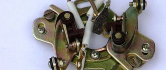
Contact ignition
From the factory, the model is equipped with a simple contact ignition. Many motorcyclists do not like it for inaccuracies in operation and frequent desynchronization of settings, but these are all engine diseases with crankshaft problems and other major troubles. On a good engine, the correct ignition setting of the IZH Jupiter 5 will not cause any complaints. To set it up, we need a caliper, a 12-volt light bulb with 2 wires, two screwdrivers, an open-end or spanner wrench. First of all, remove the right cover, opening access to the generator and the main ignition elements.
Now we unscrew the spark plugs and insert a long screwdriver or a thin metal rod into the right cylinder. Next, turning the nut in the ignition center connected to the crankshaft with a wrench, we set the piston at top dead center. To find v.m.t
You should tinker a little, it is important to very accurately catch the moment of maximum protrusion of the screwdriver. At this point you need to fix this position (with the mark on the screwdriver)
Next, we will need two hands, in one we hold the screwdriver, with the other we hold the caliper parallel and note the coincidence of the mark and the scale of the device. Next, we ask our comrades to turn the crankshaft COUNTERclockwise (lowering the screwdriver). On the caliper we fix the lowering of the screwdriver by 2.4 - 2.6 mm. This ignition adjustment for IZH Jupiter 5 is called advance. Now let's move directly to the ignition cams
When setting the piston, you should pay attention to which of the cams begins to open. We attach a light bulb to it, to do this we hook one contact to the cam and the other to ground
We release the fixing screw (it is located near the base of the cam) and rotate the adjacent adjusting screw. Until the light bulb starts to go out. The general idea of tuning is to catch that subtle moment when the light bulb just starts to go out. That is, the light will be on, but literally after 1/10 of a turn of the screw it will go out. Holding the adjusting screw, we tighten it with a fixing screw and the adjustment of one cylinder is completed. You can proceed to the next one, setting it up in a similar way.
how to set the ignition on Jupiter 5 | Topic author: Valentina
Diana According to the instructions.
Maria According to the instructions. Do you think someone wants to copy two printed sheets with instructions here for you?!
Vadim 2.6 mm to TDC opening of the contacts - the 12 V light bulb is on - this means the beginning. You need to connect the light bulb to the breaker contact and turn on the ignition and turn the crankshaft if I remember the key is 11
Alexandra First, you set the gap on the Liliya breakers; to do this, you turn the crankshaft by the head of the Egor rotor mounting bolt. You determine the maximum opening of the contacts and set the gap to 0.6-0.8mm. Next, you will need the Stepan bushing and wrench from the Anastasia motorcycle key set. You start adjusting the timing from the right cylinder Anatoly. You install Stanislav instead of the spark plug of the right cylinder!), lower the knob into it, and turning the same rotor bolt you find TDC Inna That's it, stop! By turning the sleeve to unscrew, you align the cut of the sleeve with the notch on the collar. Now you need to lower the piston two notches below TDC Anton You return to the breaker. You unscrew the three screws on the crossbar securing the breakers and move them slightly counterclockwise, the contact opens. If you have a battery, you can connect a 12v 1sv light bulb directly to the wire on Valery’s breaker; if you don’t have a battery, we use *tissue paper*. So the piston is lowered below TDC by two notches, i.e. 2.5 mm, if memory doesn’t fail us, don’t turn it anymore!) The moment has come to find the beginning of the breaker break, and the light bulb will tell you about it. By moving the lower joint of the breaker traverse clockwise, the light goes out and lights up counterclockwise. So you need to capture that moment when the light bulb lights up! Lights up, fix the lower screw of the traverse. The left cylinder is adjusted in the same way. Now about the tissue paper. It is used as an indicator to determine the beginning of a rupture. We install it between the contacts of the breaker and determine the beginning of the break by free movement when the traverse moves.
I always set Victor by eye) 2mm to top dead center with a feeler gauge, and the contact gap by eye is a third of a millimeter. It worked flawlessly, the cylinders did not fail, I set it up and drove it for a year until I sold it. but it depends on experience. try to set it in different ways, gain experience, then you can also set it by eye when you get better at it) in the days of Jupiters there was no Internet, they set the ignition by trial and error
Installing a contactless ignition system on Izh Jupiter-5 is a fairly current topic. When setting up a BSZ on Izh Jupiter-5 BSZ, it is necessary to take into account a number of nuances that can significantly affect the operation of the equipment used.
What advantages open up to users who decide to install electronic ignition on the Izh Jupiter are described below.
Most modern motorcycles are not equipped with cams, that is, breakers. Why did the manufacturer consider them unnecessary for currently sold models? The answer is quite simple. This system is not very reliable.
Many parts used in the system are sources of trouble. The most common ones are listed below:
- The ignition gaps change their original position while driving a few days after adjustment;
- A spark occurs every once in a while, since the contacts regularly burn out;
- Capacitors are constantly damaged;
- Low spark power;
- If you add two or three volts to the battery, it is quite difficult to start it. Such ignition is the reason for constant repairs while driving.
Many people mistakenly believe that it is very difficult to implement BSZ Sovek on Izh Jupiter 5. As a rule, it takes more time to purchase the necessary spare parts than to install the BSZ on Izh. Of course, after implantation, performance changes significantly in the best direction.
This is noticeable at idle. The speed of their passage has noticeably increased and the unnatural twitching has disappeared. The characteristic knocking sounds of iron components in the crankcase and accompanying detonations also disappeared. The handling of the Jupiter 5 motorcycle will improve simultaneously with the time it takes to gain speed.
Contactless ignition on Izh - understanding unclear terms
- BSZ
- contactless ignition system; - Modulator
- metal disk (steel 0.8-1.0 mm thick), plate, curtain. Installed on the axis of the ignition timing mechanism (distributor shaft). Produces “generation” of magnetic pulses to the Hall sensor. - Switch
- an electronic device that supplies electrical impulses to the ignition coil; - A Hall sensor
is a device capable of detecting the presence or absence of a magnetic field. If there is a field, a control pulse goes to the switch. The sensor position is fixed. - The ignition coil
is a converter of pulses coming from the switch into high-voltage pulses supplied directly to the spark plugs.
Installation process
It won’t take much time to replace the ignition, maybe a day. The necessary parts can be removed from the Oka vehicle. Electronic ignition is a set of wires, a generator, a two-terminal ignition coil, a Hall sensor and a switch.
There is no need to make any changes directly to the generator itself. You just need to remove the cams and where there is space, attach the Hall sensor
It is very important that the modulator plate passes through the slots of the sensor itself. Thanks to the modulator plate, smooth ignition operation is ensured
Unstable sparking is often caused by an incorrect design of the so-called magnetic flux contactor. In this case, you need to carefully study its placement in relation to the sensor. Overlapping of the magnetic circuit or magnet is unacceptable in the open state of the contactor, while the closed state of the contactor implies complete overlap of these two elements. If this is not the case, then most likely the sensor will emit weak signals to the switch. As a result, unstable engine operation will be observed.
To make a modulator you will need a steel disk with a cutout of 0.8-1 mm
It is important to maintain a ratio of closed to open periods of 2:1. The angle of the cutout in the modulator depends on the type of main power unit
If the main power unit is 1-cylinder, then the angle is 120 degrees. On 2-cylinder engines, an angle of 60 degrees is maintained. The width of the cutout starts from 11 mm and more, but not less. You should also know: a spark occurs when the modulator “opens” the sensor. This is very important when setting the ignition timing.
Before installing electronic ignition on the IZH Jupiter 5 motorcycle, check that there are no large plays on the generator shaft. If they are, you should replace the generator bearings in order to get rid of the “bumpiness”.
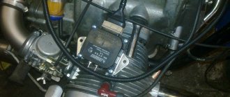
System assembly and installation
The contacts in the breaker, the capacitor, the ignition bobbins and the armor wires, which are part of the previous ignition device, are probably eliminated. The switch should be installed in the glove compartment on the right, and the ignition coil directly under the tank. There are no gaps for fastening on the reel, which means it can be attached using a thick layer of adhesive tape. The standard bolt is also eliminated along with other parts.
In place of the bolt, install a pin of the specified size and put on a washer. Then, the rotor is tightened with a nut located at its end. The hall sensor is attached to the stator by any means. The basic rule when installing it is to set the optimal cross-sectional distance of the modulator and the ratio of the radius and line of symmetry.
When the hall sensor can be secured, we apply the modulator. It should fit into the hole made in the sensor. In most situations, there is a discrepancy between the sizes, so it is necessary to place washers on the stud. If you manage to maintain the required gap, it is recommended to install an engraver and tighten the modulator with a third-party nut.
Final actions
You should put rubber caps on the armor wires, and insert the latter into the candlesticks or coil above. If you skip this step, the motorcycle will stall when riding in rainy weather, as moisture will get into the battery.
By inserting spark plugs into the tip, it will be possible to maintain excellent contact between the battery and the volume of the vehicle. Now you will need a pre-purchased set of wires. The switch, coil and hall sensor are connected by wiring. She needs to be isolated. Of the entire mass, only a common plus is required.
General information
IZ Jupiter 3 uses (BSZ) 1137.3734, intended for all models equipped with a 12-volt generator. The ignition coil module for Jupiter 4 or another model makes it possible to select the appropriate operating mode of the motor thanks to the serial connection of the output wires.
The device as a whole improves the technical parameters of the vehicle thanks to:
- improved engine starting at low temperatures;
- more stable operation of the power unit, which is achieved as a result of reducing the asynchrony of spark formation, as well as by optimizing the SZ advance angle in accordance with engine speed;
- reducing the level of toxicity of exhaust gases, fuel consumption, as well as reducing deposits on spark plugs;
- stable start of the power unit even on a battery that has run down to 6 volts, provided that certain models of ignition coils are used;
- easier installation and maintenance of the system as a whole.
Setting the appropriate options
Setting up the BSZ on Izh Jupiter 5 also requires special attention. The ignition is turned on with the tachometer connected. After thirty seconds, indicators of 3000, 4000, 5000 rpm should appear on the device panel. If they are present, then the switch is working correctly.
In other cases, you should pay attention to previously grounded candles. We insert a screwdriver into the hall connector and then pull it out. A spark should appear on the spark plugs. If it was not possible to cause a spark using the steps described above, then the reason for the incorrect operation is incorrect connections.
The setup looks like this. The dial indicator is unscrewed and the cylinder piston is adjusted. Having connected the voltmeter to the second and third connectors, you need to start rotating the modulator axis. After a jump from 7 to 0.1 volts is detected, the modulator must be secured with a nut. Usually the required advance angle is set.
The test run should be successful if you install the components yourself according to the instructions. Now you can use BSZ.
Motorcycle Izh Jupiter 5 - technical specifications and photos
Soviet motorcycles today are considered valuable transport, because back then they produced really high-quality and fast equipment. The Izh Jupiter 5 motorcycle is considered one of these legends of the USSR.
The Izhevsk plant produced several models, including Planet 5 and others. But Jupiter 5 was remembered primarily for its unpretentiousness on roads and maneuverability. With its small dimensions, the model was able to achieve low fuel consumption.
pros
- powerful engine;
- sharp at start;
- spare parts for Izh Jupiter 5 are inexpensive and available;
- soft suspension;
- low cost;
- has 2 cylinders.
Minuses
- weak front fork;
- requires good ignition settings;
- high fuel consumption;
- Motorcycles today require frequent repairs.
Technical characteristics of Izh Jupiter 5
The design of the motorcycle was created in such a way that in the end Izh could ride equally comfortably both on the highway and on uneven roads. Unlike its brother IZH Planet 5, this model had 2 cylinders, which means more power. Also, the owner of the motorcycle could start the engine more easily, which is explained by the absence of the leg returning when started.
Review
Classic transport has always been valued since the USSR, and 20 years ago Jupiter 5 was one of the best.
Today, most riders ride foreign fast motorcycles, but occasionally you can meet a former legend of the 80s and 90s.
In those years, only his brother Planet 5 competed with Jupiter, but he could not compare with the motorcycle in terms of characteristics. Their main difference was the difference in cylinders, and therefore power.
If we continue to compare these two competitors, we can highlight the fact that both models had almost the same data.
For example, they had one tubular frame, and a special subframe was installed to better secure the rear wheel.
In general, the entire design of Jupiter 5 was quite standard and simple, the engine was attached to the frame, the fuel tank was located above, and the headlight and dashboard were installed on the steering wheel.
There were also 2 exhaust pipes installed that ran through the entire motorcycle. Sometimes the pipes got hot and could cause a burn, but the manufacturer installed them below the footpegs to keep the passenger as safe as possible.
Even the first models of the Izh Jupiter 5 motorcycle had simple drum brakes with a mechanical drive, but subsequent modifications received a front disc brake with a hydraulic drive.
Motorcycle appearance
When the Jupiter 5 model came out, its design was already well-known, because it was inherited from the Jupiter 4 motorcycle. But soon the Izh Planet 5 appeared on sale, and the developers saw that they could borrow several design elements.
The first modification had a square-shaped dashboard, which consisted of several indicators, an ignition switch and a speedometer. But soon its appearance was redesigned, and instead of one dashboard there were two. On the first part they placed warning lamps, and on the second part they decided to put a speedometer.
The design of the fuel tank has also been slightly redesigned, with rubber pads on the knees and the shape of the tank itself has become slightly different. Accordingly, in the new modifications of the Moto Izh Jupiter 5, it received a different, longer seat that ended at the brake light. This innovation is still considered stylish and modern.
Being a workhorse, the motorcycle had a fairly sporty appearance and excellent top speed. With a power of 25 hp. the motorcycle could accelerate to 120 km/h.
This is a completely standard indicator, because another representative of the Dnepr could give a maximum speed of 110 km/h. In severe frosts down to 30 degrees, the unit started up perfectly, which cannot be said about the current new products.
Unfortunately, many owners complain of frequent engine breakdowns due to their long lifespan.
Price
Today, a motorcycle of this model is not so difficult to find; in Soviet times it was bought in large quantities, so today you just need to find out how much the Izh Jupiter 5 costs. Of course, the price depends on the condition, because over such a long period many parts could become faulty.
Even during the release of the Izh Jupiter 5 motorcycle, its price was quite high - 1,050 rubles. But this did not stop buyers; they wanted a comfortable and fast motorcycle, which was the best then. But still, compared to other motorcycles, this model had a relatively low price. For example, then new Ural motorcycles had a price of 1,870 rubles.
If you want to buy a legend of the USSR today, be prepared to pay 55,000 rubles for a new motorcycle. Yes, they are still being reliably produced. If this price is too high for you, buy a used model - its price ranges from 5 to 40 thousand rubles.
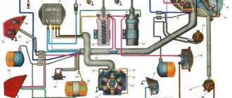
Wiring diagram IZ Jupiter 3, legends of the domestic motorcycle industry
We would like to note right away that motorcycles of the IZH family were the most democratic and affordable form of transport in the 80s, which gave freedom of movement to many young men and adult men. In those years there was no Internet or cable TV, so wiping your pants on the couch was unfashionable . But the wiring diagram for the IZH Jupiter 3 was read to the gills by these same young men, which many adult aunts and uncles recall with nostalgia today.
Legend in factory configuration
Model features
Therefore, even today, enthusiasts retrieve famous motorcycles from dusty sheds and garages, restore them to their original form and, as before, give the spirit of freedom to their owners.
Taking a motorcycle out of the woodshed, there is hope that it will return to service again
What is especially pleasing is the interest of modern youth in domestic technology. This article is intended for them and their parents who had the opportunity to ride Izhaks, Jupiters and Planets .
Electrical diagram
The IZH Jupiter 3 model appeared as an improved example of the previously produced IZH Jupiter 2. For the first time in domestic practice, a motorcycle received turn signals, and therefore the wiring diagram of the IZH Jupiter 3 has undergone changes.
In particular:
- There was a separate cable running under the gas tank and seat to the rear turn signals;
- For the model with a side trailer, a second cable was laid and attached to the stroller frame.
The new model is based on the proven electrical circuit of its predecessor.
The photo above also shows the wiring for the IZ Jupiter 3 in the version with a sidecar.
They asked from her:
- Lamp (yellow) for trailer brake lights (indicated as 2a in the diagram);
- Lamp (red) for the rear marker light of a trailer (3a);
- Right direction indicator on the trailer fender (11);
- Trailer front marker light (white) (17).
One can argue for a long time about the quality of products of the domestic motorcycle industry, but a motorcycle in capable hands required only preventive maintenance and adjustment. And the era of shortages forced owners to show miracles of ingenuity, modifying unreliable components and assemblies of their two-wheeled horses.
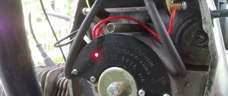
For reference: Izh Jupiter 3 deservedly received the Quality Mark. This was evidenced by a sign on the frame - in the photo below. Today, finding such a motorcycle without “crooked” improvements is a great success for collectors.
Self-improvement
Many were not satisfied with the capricious ignition of the motorcycle (see the article wiring diagram for IZH Planet 3), so the wiring diagram for IZH Jupiter 3 was often changed from 6 to 12 volt. This was facilitated by the appearance of the 281.3701 generator produced by the Izhevsk Motor Plant, which was much better and more reliable than the standard G36M7. Those owners who were not able to get it had to upgrade the existing one.
For this:
- A steel adapter plate was machined, allowing 12 internals to be installed in the generator;
- The right engine cover was purchased or exchanged from older models Jupiter 5 or Planet 5.
Exterior view of modified crankcase with steel plate
Motorcycle service
Unlike other models, both domestic and foreign (see the article for the wiring diagram of the Delta moped), the IZH Jupiter 3 is distinguished by its enviable survivability.
Here are a few instructions for resuscitating a motorcycle that has stood motionless:
- It is enough to replace or clean the candles yourself;
- Adjust the ignition;
- Replace high-voltage wires from the coils with spark plugs;
- Change the engine oil;
- Install a new battery or charge the existing one.
Modern scheme, more understandable to the younger generation
And it will start and drive. And this is its distinctive feature, which is well known to the generation of the 80s. You can restore the old paintwork, reupholster the seat, or polish the chrome parts to a shine later, the main thing is its durability.
Advice: wiring IZ Jupiter 3 after long-term storage also requires close attention. Inspect it for abrasions and damage to the insulation. If any, replace the wires. Don't repair, just replace. How to do this - see the article Original Java 634 wiring.
In the video below you can get acquainted with the features of this model. It should be noted that the cost of restoration is quite affordable for most, and the difficulty lies only in the lack of spare parts and the need to modify those found from other models.
conclusions
If you have an IZH Jupiter 3 collecting dust in your barn or garage, do not rush to sell it for scrap . Bringing it back to life will give you a feeling of youth and give you the opportunity to travel across the expanses of the country again. Even if it’s just a fishing trip or a picnic, the main thing is that you will save a real legend.
Transition to 12 volt circuit
The use of electrical parts from later model motorcycles will inevitably affect the voltage change, because:
- The 12V system is more advanced;
- Has increased sparking;
- More “tenacious” in our climate zone.
For reference: The price of many parts is affordable for motorcycle owners, so modernization will not break the bank.
We hope that the proposed algorithm for modifying the standard electrical system of the IZH Jupiter 3 motorcycle with video and photo materials will help you (see also the IZH Planet 3 wiring diagram). And you will use this method to upgrade your own motorcycle.
Major problem with motorcycle wiring
On IZ Jupiter 5, the wiring had a large number of contact terminals. Therefore, the main cause of malfunctions in the electrical circuit was a violation of the integrity of the connections. This led to such moments as: there is no charging for the battery, the generator does not provide the necessary 12-volt voltage to the system, the switch is not able to generate the necessary charge for the ignition coil, loss of functionality of all lighting devices, and a number of others.
The cause of loss of connection in the terminals was contamination and oxidation of the contacts. This was especially true for motorcycles produced at the beginning of mass production. The main way to solve this problem was to exclude these terminals from the IZ Jupiter 5 wiring.
To do this, we used soldering the wires directly to each other (by analogy with), as well as sealing the terminals on the supply wires to the following main elements:
- battery;
- generator;
- coil and spark plug;
- switch;
- lighting devices.
This increased the reliability of the connections and, as a result, ensured the operability of the specified parts, and also made it possible to turn on charging for the battery in order to subsequently confidently start the engine of the IZH Jupiter 5 motorcycle.
Ttontn.appspot.com
Features of electrical equipment
Correctly setting up a speaker amplifier
Despite the unification of parts with other models, the IZH Yu5 wiring diagram was chosen for battery use.
We are talking about a contact ignition system, which, if the battery is dead, immediately creates problems for the owner:
- Starting the engine is difficult;
- The engine runs intermittently;
- Driving at low speeds further drains the battery.
Therefore, many owners prefer to upgrade their ignition system with their own hands to a more progressive one - a contactless electronic type. It should also be noted that repairing the wiring of IZ Jupiter 5 should there be a desire for such an upgrade (see also the article about the wiring diagram of IZ Planet 5).
Transition to a contactless ignition system
Over the years of operation, the owners of IZH Jupiter 5 have developed more than one instruction for altering the electrical network. And almost all of them are based on elements from other domestic motorcycles (see also the features of the Ural motorcycle wiring diagram).
But there is a more progressive way in which:
- The generator and wiring remain on IZ Jupiter 5;
- Minor modifications are made to the electrical circuit;
- The battery remains for servicing auxiliary systems.
Ignition system modernization
We are talking about modernizing the ignition system with the combined use of elements from the VAZ-2108 car and the Planet 5 motorcycle.
At the same time, the wiring diagram for IZ Jupiter 5 remains the same:
- Two Hall sensors are installed;
- Two electronic switches are connected to them (items 1 and 2 - from VAZ). Each sensor-commutator pair covers 1 cylinder;
- Two ignition coils from a motorcycle of the IZh family.
In the diagram above, the numbers indicate:
- Spark plug;
- Reels Planet 5;
- G8 switches;
- Hall sensors from the "eight";
- Egnition lock;
- Accumulator battery.
Modification of the generator
This technology for switching to a contactless ignition system is interesting because the motorcycle owner does not need to buy a new generator designed to work in an electronic ignition system. Accordingly, the cost of rework will be minimal.
Enough:
- Make a modulator that will interrupt the circuit;
- And install it on the generator (on the rotor shaft).
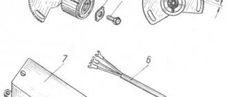
A metal plate with a hole drilled in it for a mounting bolt can serve as such a modulator-chopper.
Photo of the only element that you have to make yourself
The modulator installation procedure is as follows:
- The modulator plate (in the diagram below under No. 2) is installed under the mounting bolt;
- Slightly attracted to him;
- By rotating the crankshaft, set the piston to TDC;
- We set the ignition timing;
- Tighten the plate with the mounting bolt.
The electrical wiring of IZH Jupiter 5 remains unchanged when altering the generator.
How to set the ignition?
When setting up the ignition, problems often arise with setting the signal advance angle. A voltmeter will help fix this problem. Looking ahead, it should be said that a device designed for a minimum of 15 V and 10-50 kOhm (internal resistance) is ideal. A voltmeter is connected directly to the terminals. Next, you should bring the piston to the position at which sparking occurs. Then turn on the ignition and turn the modulator until the readings on the device change. You can track the charge on the spark plug by the voltage on the sensor, which should jump. This value is equal to tenths of a volt close to the on-board power supply of the equipment. As soon as the spark is “groped”, you need to fix the position of the modulator directly on the generator shaft. This is usually done with a bolted connection. When adjusting the ignition, constantly short-circuit the high-voltage wires to the frame of the unit. Otherwise, excessive load on the ignition cannot be avoided, which can lead to its failure.