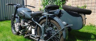
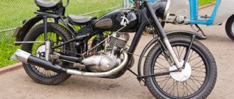
The history of the development of motorcycle manufacturing goes back to 1885, when the famous German engineer Gottlieb Daimler designed a simple motorized stroller equipped with a small kerosene engine. The frame and wheels of the first motorcycle were wooden, and its speed barely reached 12 kilometers per hour.
In the Soviet Union, motorcycles appeared in the early thirties and, in fact, they were copied from their German counterparts. The domestic motorcycle IZH-350 was an exact copy of the German DKW NZ-350, the other models of the Kyiv plant repeated the parameters of the Wanderer, a German motorcycle produced by the BMW concern.
Technical characteristics of the motorcycle Ural K 750
Technical characteristics of the K 750 motorcycle. This motorcycle began to be produced in 1959 at the Kiev Motorcycle Plant. The M 72 was taken as the basis. The type of motorcycle is troika. Its dimensions are length 2400, width 1650, height 1060. The weight of the motorcycle is 365 kg. It consumes 6 liters of gasoline per 100 km. Maximum speed is 95 km per hour. A full tank lasts for 310 km.
Boxer four-stroke engine K 750 Engine capacity 746 cm3 Compression ratio - 6.0 ± 0.2 Power 27 hp Two K-37 carburetors. Double-disc clutch in the engine flywheel. The transmission is four-speed, two-way. Battery ignition. Electric generator G-11 A.
Return to contents — ↑
Motorcycle engine K 750
The four-stroke two-cylinder power unit consists of separate mechanisms placed inside the crankcase. The gearbox 4 is attached to engine 1 using three studs and a bolt. A generator 3 is mounted on the top of the crankcase, and the ignition devices are located in the front of the engine under a removable cover 2. Carburetors 5 are attached to the cylinders.
In its design, the motor of the K 750 motorcycle is basically similar to the M-72 motor, but has the following features:
- the crankcase has holes of a different size for the camshaft bearings;
- the cylinder heads are designed in such a way that they have a smaller combustion chamber, due to which the compression ratio is increased, and therefore the power of the unit;
- the camshaft rotates on two bearings: a single-row radial and a plain bearing;
- the pistons have two oil rings;
- The cover of the timing gears is made of a slightly different configuration; moving this cover from M-72 to K-750 or vice versa is only possible together with the breather. Once assembled, the motors are interchangeable;
- with an increase in the compression ratio and power, the temperature regime has increased slightly, so the engine oil reservoir is made with fins, which replaces the oil cooler, reduces the temperature of the oil in the sump, and keeps the engine temperature at the same level;
- The efficiency of the crankcase ventilation system has been significantly increased. The table shows comparative data on the parameters of the engine ventilation systems of both motorcycles.
Return to contents — ↑
Objective of the project
The goal of the project is to create a single information space that combines a colossal amount of information that helps make the life of a biker easier and increase the level of knowledge, which, in our opinion, is extremely useful for those who have recently discovered the world of bikers and for those who have been in the saddle. We try to step forward, but not retreat from history and traditions, reflecting this on the pages of our project.
The project is free from political views, religious beliefs, alcohol preferences and gender differences. We combine all information about everyone, regardless of gender, race, motorcycle brand, absence or presence of stripes on the back, presence or absence of any sexual characteristics.
Electrical equipment of the K 750 motorcycle
The electrical equipment of the K-750 motorcycle consists of a generator - G-11A, a relay-regulator PP-31, an induction coil, a breaker-distributor PM-05, a breaker PM-11A, headlights, connecting wires and switches.
Return to contents — ↑
Generator G-11A
The G-11A generator, the device of which is shown in the figure, is installed on the K-750, M-72, M-52 and M-61. This generator is a single-pole DC electric machine with shunt excitation. Generates power for the electrical equipment of the K-750 motorcycle.
The generator power is 45 W at a rated voltage of 6 V. It works in conjunction with a relay regulator and a battery. Installed in the upper part of the engine crankcase in a special bore.
The generator is driven by the engine camshaft through a pair of gears. The gap in the gear teeth is adjusted by turning the generator housing in the engine crankcase bore. At 900 rpm. armature voltage reaches 6.5 V.
Return to contents — ↑
Relay-regulator RR-31
The relay-regulator PP-31 consists of a reverse current relay 5 and a voltage regulator 13, mounted in a common housing 7.
The reverse current relay includes a steel core with two windings (parallel and series), a yoke 5, a steel armature 2 with a moving contact, a stand 4 with a fixed contact and an armature spring 21.
The parallel (shunt) winding is made of insulated copper wire with a diameter of 0.17 mm and has 1200 turns. The serial (serial) winding has 15 turns, made of a similar wire with a diameter of 1.81 mm.
The voltage regulator includes a steel core with three windings (parallel, equalizing and correcting), a yoke 16, a steel armature 12 with contacts attached to the ends of the plates 10 and 11, an armature spring 17 with an adjusting nut 18, a limit bar 9, a magnetic shunt and additional resistances 19 (wire) and 20 (carbon).
The parallel winding has 990 turns of insulated copper wire with a diameter of 0.62 mm, and the equalizing and correction windings have 37 and 11 turns, respectively, made of similar wire with a diameter of 0.86 and 1.74 mm.
The PP-31 relay-regulator has three terminals: Sh, Z and B, which must be connected, respectively, to the terminals Sh and Z of the generator and to the ignition switch clamp. The relay is attached to the motorcycle frame under the driver's seat on the right side of the motorcycle.
Return to contents — ↑
Ignition coil B-2B or IG-4085 and B-201
The B-2B or IG-4085 ignition coil is used to convert a low voltage current (6 V) into a high voltage current (12-15 thousand V) and consists of a core 3, primary 7 and secondary 4 windings, a housing 8 and a carbolite insulator 2 with output terminals 1 and 9.
The secondary winding has 12-13 thousand turns of wire with a diameter of 0.07-0.1 mm. The secondary winding resistance is 4000 ohms.
The primary winding has 250 turns, made of wire with a diameter of 0.8 mm. The resistance of the primary winding is about 1.5 ohms.
The ignition coil consumes a current of 4 A at a voltage of 6 V. The coil must ensure uninterrupted new formation with 6000 current interruptions in the primary circuit and with a spark gap length of 7 mm on a three-electrode spark gap.
The B-201 ignition coil is mounted on the front cover of the engine and consists of an iron core, one primary and two secondary windings, two output terminals from the secondary windings and two insulators with terminal clamps for the primary winding.
High voltage current is simultaneously supplied to the spark plugs of both engine cylinders. In this case, the spark impulse is used on the spark plug of one cylinder (compression stroke), but not used on the spark plug of the other cylinder (exhaust gas release).
Return to contents — ↑
Breaker-distributor PM-05
The breaker-distributor PM-05 consists of a breaker with a rotating base and a high-voltage current distributor. The breaker consists of a housing in which a rotary disk 13 is installed, which has annular grooves. Screws with springs pass down through the grooves, with the help of which the disk is pressed against the body.
The breaker parts are mounted on the rotary disk: a fixed contact 14, with a locking screw 12 and a screw with an eccentric head 10, as well as a hammer 4, isolated from the ground and connected to the contact post through a flat spring.
Capacitor 1 is connected in parallel to the contacts of the breaker, having a capacity of 0.15 μF. The distributor rotor 18 has a central contact and a side contact plate located along the radius of the rotor flange; in this case, both contacts are connected to each other.
The rotor also has a metal sleeve and a block with a screw, with which it is secured to the end of the camshaft. The block is placed inside the shaft, and the screw passes through a slot in it, due to which the rotor is always fixed in a certain position relative to the engine camshaft.
The rotor is closed with a distributor cover with three high-voltage terminals located on it: the two outer terminals are for connecting wires from the glow plugs, and the middle one is to the central terminal of the induction coil.
Three carbon contacts are installed on the inner surface of the cover, two of which (the outer ones) 23 have spring ejectors. In the center of the cover there is a central contact 22, which, when the cover is installed on the breaker body, is connected to the central contact of the rotor 19, supplying high voltage current from the ignition coil to the side contact plate of the rotor.
The extreme carbon contacts, sliding along the rotor flange, alternately close with the plate, directing a high voltage current to one or the other engine cylinder spark plug. During one revolution of the engine camshaft, the breaker contacts open twice (every 180°), forming two sparks: one ignites the mixture in one cylinder, and the second in the other.
Return to contents — ↑
Breaker PM-11A
The breaker serves to interrupt the current in the circuit of the primary winding of the ignition coil and consists of a housing 14, a hammer 4 with a spring, an anvil 3, an adjusting screw 11, a low voltage current terminal and a capacitor 13.
Since 1963, motorcycles have used breakers of the P M-11 A type with an automatic ignition advance and a B-201 double-spark ignition coil. In this case, high voltage current is supplied to the spark plugs directly from the ignition coil.
Thanks to this, the design of the breaker is simplified: it does not have a drive mechanism for manual adjustment of the ignition timing, and the hammer with contacts turns automatically, thereby increasing the reliability of engine operation.
The timing device is installed at the end of the engine camshaft and consists of a base with a flange, an ignition cam 10, weights 6 and springs 8.
The machine works as follows. The weights, rotating together with the camshaft, diverge under the action of centrifugal force, and the weights' leads, moving along the grooves, turn the cam at a certain angle towards the textolite heel of the breaker hammer. In this case, the hammer rises and the breaker contacts break earlier, and the ignition timing increases.
Return to contents — ↑
Headlight FG-6A
The headlight F G-6 A of the K-750 motorcycle consists of a housing 1, a reflector 3 with a double-filament lamp 5, a diffuser 2 and a parking lamp 4. The central switch 6, a speedometer 9, a warning lamp and a fuse are installed in the headlight housing. The central switch is turned on using key 7.
Return to contents — ↑
Electrical circuit diagram of the K-750 motorcycle
The general diagram of the K-750 electrical equipment is shown in the figure below.
Return to contents — ↑
Transmission
Until 1963, the K 750 was equipped with an M-72 motorcycle gearbox. Later, changes were made to the design of the shift clutches, the secondary shaft and its gears.
Splines are cut on the secondary shaft, along the outer diameter of which the gears can rotate freely.
Between the gears of the first and second gears, as well as the third and fourth gears, fixed bushings are installed on the splines of the secondary shaft. These bushings also have external splines along which the movable couplings move. The internal surfaces of the couplings have small splines for engagement with the splines of the gears of the corresponding gears.
Cardan and main gears serve to transmit torque from the secondary shaft of the gearbox to the drive wheel.
The cardan transmission consists of a cardan shaft 18, an elastic coupling 16, a cross 14 and a cardan fork 21, a casing 20 and an o-ring 19.
The cardan shaft receives rotation from the secondary shaft of the gearbox through an elastic coupling consisting of two steel disks 17 connected by pins to an elastic rubber coupling.
One of the disks fits onto the driveshaft splines, and the other is installed on the end of the transmission output shaft.
The drive gear of the main gear receives rotation from the propeller shaft through a cardan joint consisting of a crosspiece and two forks with needle bearings 13. The bearings are lubricated through a grease nipple 15.
The main gear consists of the following main parts: a crankcase with a cover 26, a driving gear 24 and a driven gear 29, and a driven gear hub 5.
All the main gear parts are located in the crankcase, which is also an oil reservoir, a brake housing and a support for the right end of the wheel axle.
Gasket 30 is installed between the crankcase and the cover.
The gears are made with spiral teeth.
The drive rotates on a ball bearing 23 and a needle bearing 8.
The driven gear is connected with bolts to the hub, which rotates on a ball bearing 25 and on bronze liners 4.
Rotation of the drive wheel hub is transmitted through the internal gearing formed by hub 5 and the hub of the driven wheel gear.
Oil is poured into the main gear crankcase through a hole closed by plug 1. To prevent oil from leaking out of the crankcase, there are oil seals 11 and 7, secured with a cap 6.
Return to contents — ↑
MT8 engine of the Dnepr K-650 motorcycle
is a four-stroke air-cooled carburetor engine.
The engine uses an overhead valve timing mechanism, a cast crankshaft made of high-strength cast iron with removable lower connecting rod heads and replaceable connecting rod bearing shells. The design uses automotive-type inserts, interchangeable with the inserts of the Moskvich-408 car. The engine uses a forced lubrication system with centrifugal oil purification; bimetallic cylinders are used, which are more efficient than cast iron. Due to this, the engine has low thermal stress; the pistons in the cylinder are installed with a gap of 0.05 - 0.07 mm. The engine is reliable and durable.
Chassis of the K 750 motorcycle
The chassis of the K-750 motorcycle has undergone significant changes compared to the chassis of the M-72 motorcycle.
The K-750 motorcycle uses a double one-piece tubular frame, the peculiarity of which is a lever suspension of the rear wheel on two-stage spring-hydraulic shock absorbers.
Return to contents — ↑
Rear shock absorber K-750
The spring-hydraulic shock absorber has two stages of spring pre-compression depending on the load level of the motorcycle.
The main elastic element is spring 5. Vibrations are damped by a double-acting hydraulic shock absorber located inside the carrier spring in housing 14.
In cavity B, formed by the shock absorber body and the walls of the working cylinder of the hydraulic shock absorber 19, 70 cm3 of shock absorber fluid is poured.
The body is closed on top with a nut 8 with a self-moving oil seal 7.
The shock absorber rod 2 passes through the bearing 11 and is screwed into the tip of the shock absorber 3.
In the picture - Shock absorber of the rear suspension of the K-750 motorcycle
1 — rubber hinges; 2 - piston rod; 3 — upper shock absorber tip; 4 - key crackers; 5—carrying spring; 6 — buffer rings; 7 — oil seal; 8 - nut; 9 — thrust washer of the oil seal; 10 — rubber seal; 11 — piston rod bearings; 12 — casing; 13 - ratchet; 14 — shock absorber body; 15 — retaining ring; 16 - bypass valve; 17 - piston; 18 — rod nut; 19 — working cylinder; 20 — washer; 21 — suction valve body; 22 - suction valve; 23 — lower shock absorber tip; 24 - bolt; 25 - safety valve; 26 — suction valve spring; 27 — bypass valve spring; 28 — emphasis; 29 — ratchet support; 30 - casing; 31 — self-clamping oil seal spring; L and B - communicating cavities; B - drainage holes; G is the variable volume under the piston.
The working cylinder of the hydraulic shock absorber is clamped between the bearing 11 and the suction valve body 21 using a nut 8. A piston 17 is installed at the end of the rod, which is pressed by a nut 18 against the stop 28 and the lock ring 15. The bypass valve 16 rests on the groove of the piston, pressed by a spring 27. B In housing 21, suction 22 and safety valves 25 are installed. Valve 22 has a hole and a diametric groove that allow shock absorber fluid to flow.
Tensile shock absorber operation
When the shock absorber operates in tension, the suction valve opens and liquid from cavity B flows into cavity D under the influence of vacuum.
The liquid in cavity L is compressed and through the bypass valve 16 and the piston hole 17 begins to flow into cavity G.
At the same time, the liquid in cavity A creates resistance to the upward movement of rod 2, and the process of stretching the shock absorber is inhibited.
Compression shock absorber operation
When the shock absorber operates in compression, the liquid in cavity G is compressed, the suction valve closes, and the bypass valve opens.
In this case, liquid from cavity G flows into cavity B.
At the same time, the liquid in cavity B creates resistance to the downward movement of the rod, and the compression process is inhibited.
During sudden shocks, the fluid pressure in cavity G increases very strongly, which can lead to damage to the shock absorber.
To prevent this from happening, a safety valve 25 is introduced into the shock absorber design, which automatically opens under a pressure of 50-70 kg/cm2, and liquid from cavity D begins to intensively flow into cavity B (the second stage of shock absorption).
With significant compression, rubber buffer rings 6 are activated.
Return to contents — ↑
Front fork
The front fork is a lever type.
With easily removable double-acting horizontal hydraulic piston shock absorbers and rubber buffers.
The fork is equipped with a steering shock absorber.
Installed under the steering column of the fork and designed to make it easier to control the motorcycle while driving on bad roads.
Hydraulic shock absorbers can be disassembled and reassembled without disassembling the front fork or removing the front wheel.
The load-bearing part of the fork is an all-welded frame 2, consisting of two stays 3.
The feathers are connected to each other by a steel bridge. Spring-hydraulic shock absorbers 5 are located at the lower ends of the feathers.
When installing the fork on a motorcycle, the frame is closed at the top by a traverse 1 made of duralumin.
Strong shocks to the front wheel at the beginning of the suspension stroke are absorbed by load-bearing springs and hydraulic shock absorbers, and at the end of the stroke by rubber buffers.
The design of a two-stage spring-hydraulic shock absorber is shown in the figure, and its operation is fundamentally similar to the operation of the spring-hydraulic shock absorber of the rear suspension of the K-750 motorcycle.
Return to contents — ↑
Wheels
The wheels of the K-750 motorcycle, unlike the wheels of the M-72 motorcycle, have...
Die-cast aluminum alloy housings, interchangeable spokes and adjustable tapered roller bearings.
Aluminum supports were introduced under the spoke heads, which sharply increased their contact areas and thereby eliminated spoke breakage.
The aluminum wheel housings have cooling fins to quickly dissipate heat from the brake drums.
This made it possible to use wider brake pads and increase braking efficiency.
The wheels of the K-750 motorcycle can be installed on other Ural motorcycles, and vice versa.
Return to contents — ↑
Brakes
The brakes are shoe type, mechanically driven, compared to the brakes of the M-72 motorcycle, they have a reinforced and improved design, providing more efficient braking and significantly greater durability.
Braking mechanisms are installed on the front and rear wheels.
The stroller wheel does not have a brake mechanism.
The front wheel brake device is shown in the figure.
The brake pads are equipped with a special mechanism that compensates for uneven wear of the friction linings.
In addition, the brake pads are equipped with a balancer, which ensures effective braking even in the presence of runout of the brake drum.
The normal gap between the brake pads and the brake drum should be within 0.3 - 0.4 mm.
The gap is adjusted using a compensator.
The front brake is operated by a lever located on the right side of the handlebar.
The rear wheel brake consists of parts that are interchangeable with the front brake parts, and is operated by a foot pedal located on the right side of the motorcycle (in the direction of travel).
Return to contents — ↑
From the authors
We ourselves have been traveling the roads for a long time and know firsthand how difficult it can sometimes be to find the necessary, and most importantly, structured and understandable information about a brand, a motorcycle club, a specific motorcycle model, or other aspects of the motorcycle world. The Internet, of course, is the largest information space where you can find a lot of useful information, but it is our encyclopedia that combines all aspects of the life of a modern biker in a clearly structured, and most importantly, easy-to-understand form.
Motorcycle air filter K 750
The air cleaners of the K 750 motorcycle were installed directly in the gas tank, which will change the design of not only the air cleaner itself, but also the fuel tank with air ducts and the motorcycle frame.
On earlier motorcycles, air cleaners were mounted on the gearbox housing.
An air cleaner located in the gas tank has a number of advantages over an air cleaner installed on the gearbox. The main advantage is that the air cleaner located on the fuel tank is located in a zone of less dusty air on Ural motorcycles.
This arrangement of the air purifier ensures longer and higher-quality air purification for preparing the working mixture. The service life of the engine increases. Fuel consumption is reduced. The air purifier itself is washed less often. The operating principle of both air purifiers is the same.
Below are comparative indicators of these air purifiers. The K-750 engine is equipped with two K-37 A carburetors.
Comparative indicators of air cleaners of the K-750 motorcycle: 1. Air dust content at the level of the air cleaner, %: Air cleaner located in the fuel tank - 100 Air cleaner located on the gearbox housing - 2200 2. Dust capacity: Air cleaner located in the fuel tank. Provides normal air purification for an almost unlimited time, as it works on the principle of self-cleaning and in a low-dust environment. Air cleaner located on the gearbox housing. Provides normal air purification for 13 hours. work at air dust content of 0.15 g/m3. 3. Air purification coefficients, in%, with dust content of 0.15 g/mg and air flow: 20 cubic meters per hour Air cleaner located in the fuel tank - 93 Air cleaner located on the gearbox housing - 90 40 cubic meters per hour — Air cleaner located in the fuel tank — 94 Air cleaner located on the gearbox housing — 92.7 60 m3 per hour — Air cleaner located in the fuel tank — 97.8 Air cleaner located on the gearbox housing — Start of oil carryover 120 m in cubic meters per hour - Air cleaner located in the fuel tank - 98.5 Air cleaner located on the gearbox housing - Intensive oil carryover 4. Average fuel consumption, in l/100 km, when driving: on asphalt - Air cleaner located in the fuel tank — 6.3 Air cleaner located on the gearbox housing -7.3 cobblestones — Air cleaner located in the fuel tank — 6.8 Air cleaner located on the gearbox housing — 7.4 country roads — Air cleaner located in the fuel tank — 7 .0 Air cleaner located on the gearbox housing - 8.0
Return to contents — ↑
Since November 1978
Pistons with a head sphere radius of 72.5 mm were produced. They were installed on the MT10-36 engine when running on regular A-72 and A-76 gasoline with a compression ratio of 7.5 units. and on the engine of export motorcycles to run on high-octane A-93 gasoline with a compression ratio of 8.5 units. The distance from the piston pin axis to the outer surface is 48.2 mm.
Interesting: The 1967 Dnepr-1 motorcycle is the last survivor of the 12.
The shape of the groove for the exhaust valve in the piston has been changed. In order to maintain the compression ratio of the working mixture, a cylinder is installed on the MT10-36 engine, which differs from the cylinder of the MT8 and MT9 engines in the height of the installation size. The distance between the surfaces that are adjacent to the engine crankcase and the cylinder head is 107.7 + 0.14 mm
Piston MT10-36