GENERATOR 700 W | OPPOZIT.RU | motorcycles Ural, Dnepr, BMW
The resistance between the windings must be the same.
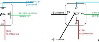
The engine is started and the rotor rotates in the stator winding, voltage is supplied to the excitation winding through the PP and the generator is excited. As practice has shown, pieces of nails driven into holes cope with the task. If the voltage is outside the technical specifications, replace the regulator. In particular, automatic ignition timing was introduced, since the motorcycle received a new power unit, and the old manual control of the timing advance did not meet the technical requirements. The voltmeter reading is noted and, by bending the shank in the voltage relay, the spring tension is increased, and with it the generator voltage by 0.4 V. An additional rectifier arm is also introduced into the electrical circuit. During this period, you can slightly increase the generator voltage.
On a URAL car there is a voltage regulator. If the voltage is outside the technical specifications, replace the regulator. Adjust the position of the front wedge stops 9 on the closed lid 6 of the container 10 after installing the batteries 1 and the upper clamps into the container. If they come out of the special sockets, the phase leads may break off during generator operation.
If the engine continues to run, then the generator is working. The work consists of connecting a generator or battery to the mains at a certain moment. Thus, by turning the additional resistance on and off, a certain generator voltage will be maintained. After installing the batteries on the car, adjust the position of the front wedge stops 9, for which loosen the tightening of the bolts 8 securing the stops 9 to the cover 6, move the stops 9 along the elongated holes of the cover 6 away from you until they stop and tighten the bolts 8.
We recommend reading:
Contact Information. Thus, by turning the additional resistance on and off, a certain generator voltage will be maintained. Remove the cover from the shaft.
But you need to follow some rules. The generator covers undergo minor modifications. Replace brushes protruding from the brush holder channel by less than 5 mm. Features of the development of electrical equipment of Ural motorcycles The six-volt circuit over the years ceased to meet technical regulations, and on subsequent models, manufacturers installed central wiring designed to operate 12V equipment: Ti-volt battery; Let's consider their structure and interaction.
Thus, by turning the additional resistance on and off, a certain generator voltage will be maintained. If the voltage is outside the technical specifications, replace the regulator. Period of years The wiring of the Ural motorcycle has also proven itself quite well - if at first the designers had concerns about loss of contact due to possible corrosion of the metal frame, then operation has shown the reliability of the single-wire electrical circuit. Scooters and mopeds Ural motorcycle wiring diagram Ural motorcycles have a unipolar battery terminal. If after several trips it turns out that the battery is not charging enough, you can further increase the voltage of the generator, but not higher than 15 V. Ural motorcycle wiring diagram
How to check the relay?
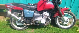
In general it was like this. I was getting ready to start my trike, which had been sitting outside all winter. After charging the battery, cleaning the contacts and replacing some substance in the gas tank with gasoline, I finally revived it. And since the ignition key was lost and the lock itself was completely broken, I could not turn off the ignition. This means the engine is working, but I don’t have the brains to take off the candle holder to turn it off (there is no engine stop). So, instead of disconnecting the positive wire going to the coil, I short it to ground. The engine died down and, in general, all signs of life along with it. I looked at the fuses, one was burned out, I replaced it, everything was still dead. To clarify, this means that the charging control lamp does not light up. Then I took a piece of wire and connected the plus directly to the coil. The lamp does not light, mind you. So I start it and the light comes on. I have a separate breaker for the generator, so I turn on the generator, the lamp starts blinking. I turn off the engine, the lamp goes out. So the main question! Which of the two relays burned out? The wiring works according to the scheme described in https://custom26.ucoz.ru/forum/5-127-1
nait9, the control light is in your hands. and check for the presence of a plus where it should be. With a multimeter in low-resistance circuits, there is little that can be adequately checked other than the integrity of the wires.
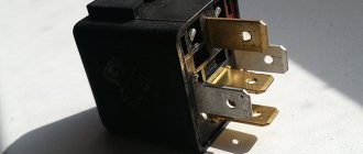
IMHO the relay-regulator burned out. When my control lamp relay burned out after a short circuit, the control lamp was constantly shining, despite the fact that the RR was regularly charging. If you buy a new RR, look for one with diagnostic LEDs. RRs are the size of a matchbox.
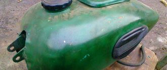
All is good! The topic can be closed. I decided to do as Vetal41rus advised. I checked the power supply to the lock using a test lamp. Not finding it there, I took a piece of wire and connected it directly from the plus of the generator to the lock. The lamp works, the engine starts, the gene snorts. Looks like the wire has burnt out. Remove the tank. I just filmed it again. Eh.
Setting up and testing the scooter
Check the power interrupt switch. This safety feature "interrupts" engine power when you apply the brakes. If your scooter does not work after adjusting the brakes, then the problem lies in this unit.
Adjustment procedures may vary depending on the scooter model. You can usually loosen the brake adjustment tension by turning the brake adjuster built into the handle toward the lever. This releases the tension on the adjustment and safety switch. Check the owner's manual or contact the motor manufacturer.
If this setup doesn't work, there is an easy way to test the generator. Disconnect it from the controller, then try to start the scooter. If the problem is with the switch, then the scooter will only work when the brake lever switch is disabled. Make sure the power switch is turned on.
Installing the fan on the motorcycle regulator relay
In a computer hardware and organizational store. technicians, we purchase a fan for the ATX power supply.
Better than Zalman and even better than aluminum or ceramic, I couldn’t find aluminum, although they are on sale, the fan size is standard 80x80mm.
If you have a motorcycle model other than the Honda VFR 800 or Honda VFR 400, then you first need to assess the space to see if the fan will fit, usually there is enough space; on the motorcycle models listed above there is more than enough space.
On Honda VFR motorcycles, the relay regulator has a radiator for better cooling, as practice shows, this radiator is not enough.
The fan cannot be glued to the radiator of the regulator relay, the latter gets very hot and no glue, with the exception of thermal glue, will withstand such a temperature. Due to the vibration, it will most likely just come off sooner or later.
How to attach a fan to a motorcycle relay regulator.
The easiest way is to make wooden spacers - a wooden dowel, also known as a “bonnet”, the width of the spacers should be exactly the same as the grinding area in order to fit between the radiator fins on the regulator relay. The size is determined experimentally, with a little pressure; do not overdo it; it is better to sharpen it.
We push spacers between the radiator fins, taking into account the width and height of the fan. If you mount the fan through the lower holes, then use 10mm screws or 25mm screws if you mount it through both eyelets of the fan, then tighten the fan to the radiator.
The wires going to the fan will have to be built up with similar ones.
The red wire on the fan is positive, the black wire is negative.
It is better to connect the fan to the side lights of the motorcycle, because... We all always drive with the lights on, and our lights are always on as well.
Look at the photo and questions about the mechanical installation of cooling will disappear by themselves; if they arise, it’s just not always clear from the description.
Electrically, there is also nothing complicated, you just need to determine the negative wire and the positive wire on the side lights, you can resort to reading the instructions (manual) for the motorcycle, or use the outside help of a more knowledgeable motorcycle partner, or simply use a voltmeter.
If you are not familiar with a multimeter, then in a nutshell you can find out where the plus and where the minus of the two wires is.
We set the multimeter to the “Volts (V)” measurement mode; next to it, there is not a sine wave drawn, but a straight line.
We touch the wires with probes, if the screen shows, for example, the value “–11.86V”, it means that where the black wire is, there is a positive wire on the motorcycle. If the value on the screen is without the “-” sign, then the positive wire will be under the red probe.
What other relay regulators can the fan be installed on?
I would also like to add that for those relay regulators that heat up and do not have their own radiator, the installed “cooler” from the computer processor, both with and without a radiator, helps a lot, it is possible to bring it down to 10-25 degrees, which in itself In some cases, the relay regulator saves itself.
However, installing a fan of even a smaller diameter in a narrow place is sometimes extremely difficult, then use a fan for video cards, again computer ones, such fans can be glued using thermal glue, in no case should you use ordinary glue, any strings, clothespins, etc. you need to make sure that it lasts forever and in no case falls off anywhere at high speeds.
It is highly advisable to add comments to the article, if there are any, of course.
Types of multimeters and the principle of their design
The most common types of multimeters are analog and digital. Let's look at how they are designed and work below.
Analog
These are old-style testers that look like boxes with a glazed arc-shaped scale and a spring-loaded pointer. Often there is a mirror arc on the scale so that when you look at the arrow you can align the arrow with its reflection. This way, when measuring, you are looking exactly perpendicular to the scale, rather than at an angle, and it will be more difficult for you to make a mistake. The measuring panel has many parallel arc scales for different types of measurements:
Analog multimeter.
One of the main advantages of an analog multimeter is its low price and measurement accuracy that is quite sufficient for everyday purposes. Moreover, most analog multimeters have a built-in special resistor to adjust the position of the arrow exactly to “0”. For adjustment, a resistor head is used, similar to a screw slot, located below the measuring scale approximately at the point where the arrow is attached.
Digital
These multimeters are more modern and look like oblong black boxes with a large liquid crystal display for digital readings. These devices got their name because the analog signals entering the device are converted into digital form in an analog-to-digital converter (ADC). Such devices are more expensive than analog ones, but their size and weight are somewhat smaller, and it is more convenient and faster to work with them.
Some models are well suited for working in complete darkness due to the ability to illuminate the indicator panel (and electricians often have to work in dark rooms). You simply press a button and the panel lights up. In addition, you can find a model with the ability to record the readings taken into the device’s memory and subsequently transfer this data to a computer for further analysis. To do this, just press a special button. Typically, digital devices are used by professional electricians, electronics engineers and engineers.
Digital multimeter.
The measurement kit includes two wires with terminals and pointed probes:
- one black wire – “minus”, “ground”, “com” (common);
- the second red wire is positive or “measuring”.
It will be interesting How to check a resistor with a multimeter
The black probe is usually applied to the body of the electrical appliance (common busbar) or attached with a special clip - an “alligator clip”. The red probe is most often taken in the right hand and applied to different places in the circuit. The probes included in the digital multimeter are the same as those in the analog multimeter. Often the sockets are color-coded - red and black frames, so as not to accidentally confuse which probe is inserted where.
Sometimes the multimeter is a built-in part of another device, such as a digital clamp meter. Due to the need to be large, such devices have a large amount of free space in their housing, where the multimeter is built in.
How to check PP with a multimeter on a moped?
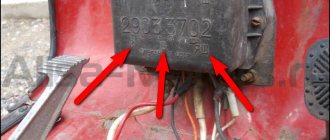
The relay regulator on a Chinese scooter is checked using a multimeter with a voltmeter function. For this purpose, a simple DT-830 (or equivalent) is usually used. It is better to carry out diagnostics and measurement of output voltage with the device removed.
Verification algorithm:
- You need to unscrew the fairing with the central phase and find on the frame a device with 4 wires: red, green, yellow and white.
- Then start the scooter and check the voltage at idle: measure it between the green and red wires, setting the multimeter to the maximum value of 20 V.
- If the multimeter display shows a figure of 14.6-14.8 V, this is normal. For stabilizers on Chinese mopeds, this is the operating standard voltage. If at idle the multimeter shows a value of 15-16 V, this is a high voltage indicator. This indicates a malfunction of the relay regulator.
- Then you need to check the voltage supplied to the lighting lamps. An alternating voltage is supplied to the central low beam (high beam) lamp, so the multimeter should be switched to the alternating current measurement mode with a parameter of 20 V.
- Next, we measure the voltage between the green and yellow wires (green is the general electrical network of the moped). If the multimeter shows a network voltage of up to 12 V, then the electrical appliances are operating without additional load.
- If at idle this value is 16 V or higher, and with a sharp increase in engine speed it jumps to 25 V, the device does not stabilize the voltage and, therefore, does not work. With such readings, the device must be replaced with a new one.
Using a multimeter, they check the relay regulator on a Chinese scooter.
In order to make a measurement, you need to:
- switch the device to the “KiloOhm” mode and remove the regulator;
- then place the probes on the first pair of terminals (AB). The tester should show a value of no more than 18 kOhm;
- after that, we change the position of the probes on the terminals in the opposite direction (VA) and measure the voltage again - the arrow on the device should show 0;
- then we install the probes on the next pair of terminals (SD) and measure the readings on this pair;
- swap the probes (DS) and measure the indicator again;
- the remaining measurements have no contact and are not checked. The indicator when checking them should be zero.
In this way, regulators are tested on popular Japanese models with small engine volumes from brands such as Honda (Leard, Dio, Tact), Suzuki, Yamaha.
Replacing a faulty relay regulator on a scooter is not difficult.
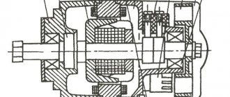
The simplest generator
The simplest generator is a metal rod with a wire wound around it. If a permanent magnet is moved under the rod, the rod will be magnetized in different directions, and the alternating magnetic field arising in the wire will cause current pulses of alternating polarity.
The current arising in the conductor is directly proportional to the strength of the magnetic field, the speed of movement of the magnet and the number of turns of wire around the rod.
The generator will take on its usual appearance if the translational movement of the magnet is replaced with a rotational one and the coils in which the current arises are placed in a circle. However, it will be possible to regulate the current in such a generator only by engine speed, and this is very inconvenient.
Signs that a check is needed
If the battery on your scooter often runs out, and it is still quite new, this means that there is a problem with the operation of the relay regulator. As practice shows, it burns out quite often. If the device is faulty, the battery stops charging completely and loses its capacity. This means you won’t be able to start the scooter with a button; you’ll have to start it with a kickstarter.
Another characteristic sign of incorrect operation of the device may be the frequent burnout of incandescent light bulbs. They themselves are durable and have a good durability, but are quite sensitive to voltage changes. This happens because the optimal voltage in the scooter network is considered to be 12-13 V. Increasing this value even by 2 V reduces the service life of electronics and components by 2 times.
Signs of a malfunctioning regulator are identical for all models of Chinese scooters. They are especially typical for charging relays for scooters of Chinese models with an engine capacity of 50 cc. Therefore, before making a decision to replace something in electronics, testing systems and devices should begin with the relay regulator.
For all models of Chinese scooters, the symptoms of a malfunction of the regulator are identical.
What is Voltage Regulation?
A voltage regulator is an electronic or electrical device that can maintain the voltage of a power source within suitable limits.
Electrical equipment connected to a voltage source must be able to withstand the magnitude of this voltage. The source voltage must be within a certain range acceptable to the connected equipment. This goal is achieved by implementing a voltage regulator. A voltage regulator - as it implies the same thing - regulates the voltage, regardless of the input voltage adjustments or the connected load. It acts as a shield to protect devices from damage. It can regulate both AC and DC voltage, depending on its design. After you study our article, you can buy a 10 kW stabilizer.
Checking the ignition coil
Disconnect the battery and remove the beak on the scooter. We disconnect the connector on the switch and measure the resistance on the coil with a meter. We put one probe in the connector on the black wire, and the second on the negative (green wire). There should be 4 ohms - this means that the wiring and the primary winding of the coil are working properly.
Next step.
We check the second winding of the coil. We take out the probe from the contact of the green wire and insert it into the candlestick instead of the candle. And we leave the other probe on the contact of the h/w wire. The resistance should be about 7.85 kOhm. This indicates that the second winding, the armored wire and the candlestick itself are in good working order.
And if the device shows a break (i.e. does not react at all), then remove and check the candlestick and armored wire separately. If they ring, it means a break has occurred in the ignition coil. It cannot be repaired, it is solid, you will have to replace it with a new one. It's inexpensive and you can always buy it without any problems.
need a relay.
New member
Hi all! The situation is as follows: the second battery has already swollen: sos: most likely the regulator relay has run out. motorcycle: Monster s4 916 2001
maybe someone has it?
New member
New member
If you remember, it will be mega cool. Otherwise I don’t really want to wait until the end of September.
Hello Vasily with the plow. By the way, we are neighbors, I’m across the road where the sportsmaster is
New member
New member
Yes, people, remember.
come visit for some tea
Scheme and principle of operation
The operation of the stabilizer for all models is almost the same and consists in distributing the current supplied from the generator to stabilize it and further distribute it to consumers.
The operation of the stabilizer is almost the same for all models
The main peripheral consumers of the scooter include:
- battery;
- indicators;
- light bulbs;
- sensors;
- enrichment agent;
- other nodes;
- starting enrichment.
How does the stabilizer work? The main principle of its operation is to act as a transformer, which lowers the voltage to an optimal level acceptable for the operation of electrical appliances, and also stabilizes the network and prevents unexpected power surges.
To avoid these problems and their undesirable consequences, you should know the basics of the correct operation of the electrical circuit and voltage components of the scooter (Figure 1).
Voltage relay pinout diagram and wiring for main scooter models
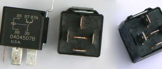
The pinout of the relay regulator is standard for all models of Chinese-made scooters.
Scooter relay-regulator pinout
The stabilizer has an aluminum body and plastic contacts, each of which has its own wire. Each contact has its own wire color. This makes it convenient to connect the device to the wires if the plastic connector is worn out. The wires must be connected to the contacts according to the electrical diagram (Figure 3).
Electrical diagram for connecting the relay regulator
Disadvantages of Shunt Regulators
Although smart regulators are suitable for all types of boat generators and batteries, installation may seem difficult for those without previous electrical knowledge. In some cases, in order to connect the regulator, you will need to determine the type of generator being used and remove it from the engine. In addition, it is not recommended to install shunt voltage regulators on new outboard motors, so as not to violate their warranty.
Sterling Power Alternator Charger up to 120 Amp (12 Volt) allows deep cycle battery charging and multiple battery connections up to five times faster
Installation complications and warranty issues can be avoided by using onboard chargers powered by the boat's generator. They also charge batteries in three stages, work with generators up to 400 A and produce voltages of 12, 24 or 36 volts. Powerful models have built-in split diodes for connecting multiple batteries.
Waterproof charger Sterling Power BBW 1212. Charging current up to 25 amperes. Powered by a boat motor generator. Connects to the starter battery and starts working only after it is fully charged
Ask a question,
and get advice on outboard electric motors, batteries or chargers for a boat or yacht