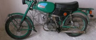
I once had such a device. And if you don’t even want to remember all the other outliers of the Soviet motorcycle industry. I have only warm memories about this moped. Yes, he had a lot of shortcomings, but at that time, owning a “Karpacz” as we called him back then was very, very cool.
They asked me to put the allegedly still quite “good” (as the owner said: it has a spark and you just need to tune it and check the first gear as it was knocking out. Well, we’ll see...) moped. As often happens in practice, a supposedly “good” one turns out to be complete rubbish. My further intervention in the technical part of this issue only confirmed this truth.
A quick inspection revealed extensive areas of corrosion, crooked wheels, a frame torn in three places, broken sprockets and chain, missing many bolts and much more.
I remembered my youth, brought a table with tools to the moped and set to work with the same enthusiasm. And there was a lot to do here...
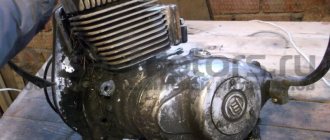
Apparently the roof was leaking in the barn. How else can we explain the presence of water in the generator cover?.. To my surprise, given the state of the generator, there was a spark, and a good one at that.
Clutch
The weakest component in the engine of this moped is the clutch. And it fails first. Oh, and we suffered with this clutch, not only on “Karpaty”, but also on “Riga” and “Verkhovyna”.
In this clutch, the release lever was screwed in first. In those days we called it “bronze finger”. At that time, this device was in terrible short supply and it was simply impossible to find it.
In the one I tested, the release valve was in working order. As they say, he still has to walk and walk.
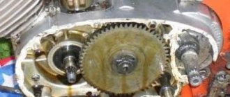
For those who don’t know, the release lever is located here. Pay attention to how much chips and dirt there are in this engine.
The second weak point of the clutch is its pressure plate, in which it constantly breaks the locking grooves, causing it to fly off the basket.
Removing the pressure disk is very simple: insert a screwdriver into a special hole, hit it a couple of times with a hammer and the disk comes off.
In this example, the grooves through which the disc engages with the basket are still good. Sometimes they are so broken that the disk simply no longer holds on. In such cases, the disk had to be replaced.
The clutch basket spring does not cause any trouble.
The nut that secures the inner drum of the basket was no longer original. There was no thread on it, just like on the crankshaft journal, and it was simply flattened and hammered onto the shaft. It is worth saying that the thread and this entire assembly as a whole are very flimsy. And because of this, the threads constantly screw up and break the splines. And on all engines of this series without exception.
If your nut turns out to be well tightened (which happens very, very rarely), fix the piston through the outlet window with a screwdriver and unscrew it.
The collective farm grower who slapped the nut under the nut did not solve the situation with its spontaneous unscrewing. This is not surprising - the problem is not in the nut, but in the level of technical literacy of the creators of this engine.
The inner drum splines are badly worn. Rapid wear of the splines of this pair is a typical problem with engines of this series.
On all clutch pressure plates without exception, the fingers with which they engage with each other dangle. I put them on the anvil, riveted them on the reverse side and forgot about this problem for a while.
Clutch discs, unlike other clutch parts, do not cause unnecessary trouble.
Often and thickly, the gear breaks off on the outer drum of the clutch basket. I corrected this situation something like this: I put the torn gear back into the basket, pressed it against the basket with a clamp, poured water into the jar, laid the basket on the jar so that the gear was completely hidden in the water and welded it to the body. Then I polished the welds and got a fully functional basket.
The basket on this example is perfect.
The spacer bushing for the outer drum was no longer original and most likely homemade.
We fix the gearbox input shaft gear from turning, unbend the lock washer and unscrew the nut.
The driven gear never breaks and runs for decades. And for some reason the nut that holds it does not unscrew... How can this be done??? Two almost identical units are located next to each other, made at the same factory, developed by the same designers. But no. The nut on the basket unscrews, but not on the gearbox input shaft. What is this? Another paradox? A mystery of nature? The machinations of evil spirits? Accident?
Carpathians tuning
Publication date Dec 28, 2013, Category: Scooter |
Carpathians tuning , thinking about this, you can come to the following conclusions. The Karpaty moped can easily be called one of the most popular mopeds throughout Russia. He “achieved” this thanks to the quality of his build, as well as various technical characteristics, which, compared to other two-wheeled vehicles of this type, look quite good. At its core, the Karpaty is a kind of small motorcycle, with a seat for 2 people, which, at the time its production began, was absent in mopeds of other models.
Currently, the tuning of the Karpaty moped that you want to do is made with a three-pad clutch and two gears in the box. According to the technical instructions, the moped can be accelerated to a speed of 45 km. per hour, although, in fact, there were cases when it accelerated to 60 km. at one o'clock. Speaking of tuning, experts recommend, first of all, changing the sprocket, installing a larger diameter, which will significantly increase the speed of the Karpaty moped, although, due to the fact that the engine is still rather weak, you will have to start as before, using acceleration, or with “ paws.”
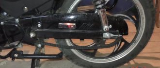
Another advantage of the Karpaty moped is that tuning with it is a pleasure, since all the parts from which it is constructed are made of good metal, with a minimum content of plastic elements. In a word, no savings were made on its production. The moped has quite strong and stable rear shock absorbers, as well as a good trunk that does not fall apart after a couple of attempts to carry a heavy load on it. Since the Karpaty moped is equipped with high-profile tires, this makes it possible to operate it in the winter season.
The piston engine of a moped does not differ significantly from the piston engine of modern Japanese scooters, and the ease of assembly allows any user to replace the piston engine or make other repairs to the power unit. Of course, if desired, and to increase engine power, you can tune the Karpaty moped, namely, bore the cylinder and install larger pistons, which, also, will not be very difficult, just like the V-50 engines installed on this moped. have been famously known for a long time; at one time, more than one generation took it apart down to the “cogs.”
Piston
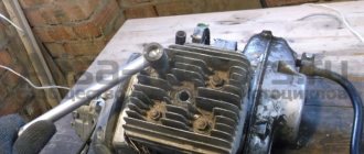
Unscrew the nuts on the head and remove it from the cylinder. The head and piston for this engine were pristinely clean. Apparently, just before this moped departed for the “other world,” they had already tinkered with it.
The cylinder was removed with great difficulty. Water got into the holes where the pins go and the whole thing became very rusty. A piece fell off from the piston on the exhaust side. This moment is clearly visible in the photo. How did he fly away? Who knows?.. Maybe they broke it off, or maybe it flew off...
The cylinder mirror was in poor condition. The wear and scratches did their job: compression in the combustion chamber dropped significantly.
The total wear of the piston group was more than 0.09 mm, with a norm of 0.05. For those who don’t know: the wear of the piston group is measured as follows: we wash the piston and cylinder from dirt and old oil residues, insert the piston into the cylinder, orient it in the cylinder as it should stand on the engine, align its skirt with the edge of the cylinder and measure the gap with a feeler gauge between the skirt and the cylinder.
This gap will determine the degree of wear of the piston group. For Soviet garbage dumps, when using very good oil, the norm is 0.03 mm, for bad oil 0.05 mm. Anything more means increased wear.
Collective farm gurus naively believe that the situation with piston wear can be solved by installing new rings. You don’t see these fabrications. And this is not fabrication, but an eternal search for freebies - this is where all sorts of stories about rings and “suprotec” are born.
No rings, even the most “duper” ones, will restore the original geometry of the cylinder and will never fit tightly to a cylinder that has wear in the form of a cone and an ellipse. And for internal combustion engine cylinders, cylinder wear only occurs in the form of a cone along the longitudinal axis and in the form of an ellipse in the transverse axis.
Think for yourself: how can an ideal circle in the form of a new piston ring fit tightly onto an ellipse? She won't lie down.
Improvement of the ignition system of Alpha mopeds
Modern mopeds and scooters are equipped with an electronic ignition system CDI (from the English Capacitor Discharge Ignition), popular with us since the 70s of the last century and called thyristor or capacitor. It is based on discharging a capacitor through the primary winding of the ignition coil and an open thyristor to produce sparking in the spark plugs. However, adjustment of the ignition angle (AF) on these mopeds is not provided. The author, through simple changes in the switch block circuit, introduced ultrasonic adjustment, which qualitatively affected the operation of the engine.
The ignition system of the Alpha moped is very simple and reliable. But still, it has one significant drawback - the lack of ignition angle adjustment. During operation, when the engine was idling and at low speeds, the ignition system sparked too early. This manifested itself in a strong kickback when starting the engine, and at idle speed it could even stop by pulling the electric starter chain in the opposite direction.
Rice. 1. Switch block diagram
The diagram of the switch block (hereinafter referred to as the switch) of the CDI AC system, installed by the manufacturer on my moped, is shown in Fig. 1. It is shown simplified, but sufficient to understand the principle of its operation as part of the system. Ignition coil T1 with spark plug FV1 is located outside the switch and is shown conditionally. In the process of analyzing the operation of the ignition system, the following feature of spark formation was revealed. When a special protrusion on the generator rotor (flywheel) passes past the induction sensor, two pulses appear at its output and enter the commutator. The first, earlier positive polarity, occurs when the protrusion approaches the sensor, and the second, later negative polarity occurs when the protrusion moves away from the sensor. Sparking (further ignition) in the spark plug occurs from the first pulse entering the switch, and the second (later negative polarity) is not used in the operation of the ignition system. The idea arose to use both impulses in the operation of the system, and so that at low engine speeds the ignition would be later, and at higher speeds it would become earlier. This required the development of both a new circuit and switch design.
Rice. 2. Diagram of the developed switch
The diagram of the developed switch is shown in Fig. 2. In order for the device to respond to pulses of different polarities, the thyristor (VS1, Fig. 1) was replaced by a triac VS1, and a zener diode VD4 was installed to select control pulses. When the engine is idling and at low speeds, the amplitude of the pulses coming from the induction sensor is less than the stabilization voltage of the zener diode VD4, therefore only later pulses of negative polarity pass to the input of the triac VS1, for which the zener diode is connected like a regular diode in the forward direction. As the engine speed increases, the amplitude of the control pulses coming from the sensor increases and at a rotation speed of about 2500...3000 rpm reaches 12 V. At this moment, the zener diode breaks through from the pulses of positive polarity, and a current begins to flow through the control electrode of the triac VS1, causing opening it. The engine starts to operate at an earlier ignition angle. The speed at which switching from later to earlier ignition occurs depends on the stabilization voltage of the zener diode, so it can be adjusted within a wide range by changing the stabilization voltage from 3.3 to 20...30 V by selecting the zener diode. When selecting, it is necessary, as already mentioned above, to use zener diodes with a direct current-voltage characteristic, like a conventional diode. To increase the spark energy, the capacitance of capacitor C1 was increased to 1.5 μF
The design of the standard switch is non-separable and cannot be repaired (the manufacturer fills the board with the elements with epoxy resin). Therefore, when making a new switch, I used only the plug connector (XP1) from the standard one.
The printed circuit board and the arrangement of elements are shown in Fig. 3. Instead of etching, conductive paths can be cut with a cutter. The width between the tracks is about 2 mm. After assembly, the device is placed in a suitable plastic box. To waterproof the joints, it is advisable to coat them with sealant. It took me about three hours to make the entire structure.
Rice. 3. Printed circuit board and arrangement of elements
Rice. 4. Appearance of the structure
The functionality of the assembled switch is checked using a car strobe light. At low engine speeds, a single mark with an F symbol will be visible in the inspection window located on the left protective cover of the generator rotor. The marks on the flywheel are made in the form of notches and are not very visible. Therefore, when setting up the device, I advise you to outline them with a black felt-tip pen through the viewing window, then they will be clearly visible when illuminated by a strobe light. With an increase in the speed to approximately 2500...3000 rpm, the ignition angle abruptly switches to an earlier one, and a double risk appears in the viewing window - the engine begins to operate in normal operating mode. In this case, negative polarity pulses from the sensor, as mentioned above, are ignored by the switch. Since the amplitude of the signal coming from the sensor varies from 1...2 V at the lowest engine speeds to 30...40 V at the highest, you can experiment and select any ignition angle switching frequency. A voltage of 9...12 V approximately corresponds to a frequency of 2500...3000 rpm, which, in my opinion, is optimal for such mopeds.
I used this switch for two seasons, and it showed its best side. When starting the engine, the strong kickback disappeared and its operation became more elastic. I think that this modification will have a positive effect on the service life of the engine.
Author: A. Shuvav, Petushki, Vladimir region.
checkpoint
Remove the bolts on the crankcase.
We take a technical hair dryer, heat the crankcase with it, warm the places under the bearings especially well and hit the shafts with a mallet to “halve” the engine.
The gearbox parts in this particular engine were of disgusting quality. On those still old mopeds, the parts were much better quality than on this example. It’s not surprising - this moped was produced in 1994, and in those years the quality of the products dropped many times over.
The cam clutches on the gearbox parts of this engine are somehow strange. Either they came like this from the factory, or someone had already managed to take them away from the collective farm. Unclear. Only one thing is clear: the quality is complete guano, even in the photo you can see how the coupling cams were simply cut either with a “grinder” or on a machine - I still don’t understand.
The carriage that includes the gears had severe wear on the edges of the jaw couplings. Hence the problems with the transmission jumping out.
Crankshaft
The crankshaft was loose and needed to be replaced with a new one or just the connecting rod.
The threads for some of the bolts were torn off and to prevent the bolts from falling out, someone flattened them and hammered them in with a hammer. We did the same with the drain plug.
By and large, there is nothing more to say about this engine. In addition to these, there are many more jambs in it, and the site’s resources are not unlimited, so, perhaps, I’ll summarize.
I took all this junk apart, washed it, rejected the parts and made a list of what I needed to buy. And then incomprehensible conversations began, which I really don’t like: they say, “you repair it.” — What about spare parts? “Yes, you understand, there’s no money now, it’s a lot of money” (...)
I waited, I waited for the financial tranche, but it never came. I collected these shakes in a bag, threw them into the cradle and sent this “Karpacz” back to where he came to me from.
Generator 26.3701
The generator is designed to work as a source of electrical energy in the electrical equipment system of mopeds with an engine with a working volume of 50 cm3. Works complete with high-voltage transformer 21.3705 and electronic switch-stabilizer unit 251.3734 (252.3734). Operating conditions: ambient temperature from -40 to +90 °C, relative air humidity 95% at 40 °C. The generator is manufactured in the following climatic versions: U, T. The rotor is a permanent magnet cast from a special alloy. It is installed on a conical shaft journal, secured with a key and secured with a bolt. The sensor magnet is located on the front of the rotor. In the stator housing, made of sheets of electrical steel, there are eight coils: two of them generate current for the ignition coil, the remaining six - to power the headlight, brake light, tail light and sound signal. A magnetic shunt made of magnetic steel is installed on the charging coils. Output terminals are mounted on the front cover.
Specifications
Generator. AC, synchronous excitation. from permanent magnets
Stator. tape 08kp-M-NT-2-0-1.5 number of grooves. 8 number of coils and their connection: in the lighting circuit. 6, serial in the ignition charging circuit. 2, serial in the sensor circuit. 1
number of turns in the coil of the lighting circuit. 25 brand and diameter of the wire of the lighting circuit coils. PEV-2; 1.08 mm
number of turns in the charging coil. 1650 brand and diameter of the wire of the charging coils. PEV-2; 0.12 mm
number of turns in the sensor winding. 1000 brand and diameter of the sensor winding wire. PEV-2; 0.15 mm
Resistance, Ohm: lighting circuits. 0.3 charging ignition circuit. 430 sensor circuit. 40
Rotor. with the main permanent magnet UND4 and the ignition system sensor magnet; Filled with aluminum alloy Cover. tape 10kp-M-NT-2-O-1.5
Execution: according to the method of suppressing radio interference. unshielded in terms of protection against penetration of foreign bodies and water. 1ROO (GOST 14254-80)
Mount: sgatora. flanged, with screws in the rotor engine crankcase. bolt on the crankshaft shank cone. Weight, kg. 2
90% service life before the first major overhaul (moped mileage), thousand km. 15 Warranty period of operation with operating time of no more than 6 thousand km of moped mileage, months. . 18