To view the contents of the instructions, you will need Adobe Reader or DjVu.
If they are not installed on your computer, then Adobe Reader can be downloaded from the Adobe website, and DjVu from the DjVu website
See also other instructions in the Mopeds section:
See also other instructions in the Stels section:
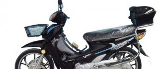
Instructions for STELS Skif 50 in Russian in pdf format for the device: scooter. Read the instructions to become familiar with the functions and operating conditions, characteristics and troubleshooting methods. This user manual will help you use all the functionality of the product and increase its service life, provided that all the rules set out in the document are followed.
Electrical diagram of a Chinese scooter - free download
I am sharing with you my personal collection of electrical circuits for Chinese scooters that I found on the Internet. Unfortunately, the technical capabilities of the site do not allow displaying the diagrams in the original size, so I advise you to download the diagrams to your computer where you can view them in more detail. Just in case, do not forget to check them for viruses.
Schematic diagram of switch connection.
Admin
You may also like
Electrical diagram of motor scooters “Tourist”, “Tulitsa”, “Ant”
Connection diagram (pinout) of the scooter switch
Electrical diagram of motorcycles “Voskhod-3m”, “Voskhod-3m-01”, “Owl”, “Farmer”
to "Wiring diagram of a Chinese scooter - free download"
Good afternoon, sorry if this is off topic, but I couldn’t find anything suitable for what topic to write. The question is today I suddenly braked and found that the speedometer stopped working, what could be the reason? Is it also possible to install xenon on a scooter? Scooter racer taurus
1alexiss1, regarding the speedometer: unscrew the drive cable from the speedometer itself and spin the front wheel, the inner cable should rotate. If there is no rotation, then something is wrong with the drive, you need to remove the front wheel and see what's what. If the cable rotates, then the problem is in the speedometer. Regarding xenon: xenon can be installed on any scooter, even KAMAZ, it doesn’t matter. The main thing is to carefully study the parameters of a particular ignition unit: what current it consumes, whether it has dust and moisture protection, the vibration resistance of a particular unit must also be taken into account, that is, see whether a specific model of the unit will suit your scooter or not. Like this.
Actually, regarding xenon, I’m now waiting for the Chinese to receive xenon at their warehouse, and I want to create an article about installing xenon on a scooter, since the owners of this equipment are so interested. By the way, I will focus on installing xenon without any modifications or alterations to the generator .. Of course, there are articles on this topic on the Internet, but there we are talking about removing and altering the generator, and on top of all this you still need to spend a X amount of money to purchase shunt voltage regulator. A beginner, I think, will not be able to do such meticulous work.
Evgeniy, the article on installing xenon on a scooter will undoubtedly be very useful and interesting for readers. So we'll be looking forward to it. Regarding the alteration of the generator: if possible, please share the links, I would like to get acquainted.
Dobrij denj,nuzen vaw sovet.U menja malaguti ciak 125cc 2006god,kogda zavodil so startera,neskoljko raz sliwal zvuk,kak budto karatilo gdeto,polez razbiratj smotretj nenawel,stal probovatj zavoditj starter krutit no nezavoditsa,vikr util sve4u mokraja, checked iskri netu. Vse predohraniteli celie,provoda nacal prozvanivatj i td vplotj do Zamka zaziganija vse ok.Nacal testerom proverjatj naprjazenie v konce kogda krutiw starterom,v 1sekundu kogda tolko nacinaew krutitj pojavljaetsja i srazu ze propadaet,pitalsa najti sxem u zaziganija.negde i necego!!ewe pocemuto 2provoda idut cerez korobku s ograni4iteljem skorosti,i odin provod cerez pol motorolera k gudku(dlja cego?) signalizacii netu,imobilajzera toze vrode… vse golovu lomajut.Estj podozrenie who generat0r??
Can you suggest a website selling spare parts for the MOTOLIFE CY50T -7 B (SPOTY) 4-stroke scooter? I can’t find anything on the Internet.
And I have this question, I don’t know much about electrical stuff at all, but on the color diagram of the voltage relay there are 4 wires, but I don’t have 5 black wires, I have 150 cc. Chinese pioneer admiral, some kind of ass with the electrics, everything seems to be normal, but there seems to be a short circuit on the yellow wire, there is such a pile of wires, what should I do, remove all the wiring?
Hej. Strona co jakiś czas nie działa, dlaczego ?
Where to download the operating and repair instructions for the Sonik GPX 150 motorcycle
The collars are ON, the engine is not running, turn off the engine. Everything is fine? Are we learning?
Add a comment Cancel reply
This site uses Akismet to reduce spam. Find out how your comment data is processed.
Source
Electrical circuit diagram of a scooter
Every car, motorcycle, moped, and scooter has electrical wiring - wires connecting electronic components, blocks and modules of equipment.
The correct operation of all systems, and in our case the scooter as a whole, depends on its serviceability. Today we will look at various options for schematic diagrams of the electrical wiring of a scooter. Electrical wiring diagrams for scooters differ depending on their model. Below, the article offers various options for scooter schemes, perhaps one will suit you. If you do not have a diagram specifically for your scooter model, then you can use one of the proposed standard diagrams below:
A simple typical scooter diagram
Electrical diagram of the scooter STILET-150Z, JOKER-150Z
Electrical diagram of the DINK-125 scooter
Electrical diagram of the scooter VITALITY-50 2T
Wiring diagram for LIFAN/ZiD scooters - LIFAN LF50QT-15,
LF50QT-8A/9, Viper Booster, Race 1/2/3, Grand Prix, Phantom, Reggy Bizon
Electrical diagram of REGGY scooter
VIPER ACTIVE scooter wiring diagram
PATRON JOKER 50 scooter wiring diagram
Scooter wiring diagram. Engine 139QMB ("Poltosy")
SHARE WITH YOUR FRIENDS
Delta moped wiring diagram china
The electrical circuit diagram of Chinese scooters is shown in the figure:
As with other electrical connections, there is a common wire on all cube mopeds. In this diagram it is the negative tire running along the entire body. The corresponding battery terminal is also connected to the scooter's frame, ensuring that each electrical component's ground is in constant contact with the power source.
Electrics and electrical equipment of a scooter
The main components in the 4t moped circuit are:
- central locking;
- battery charging source – generator;
- voltage limiter;
- spark formation and control systems;
- control elements for headlights, brake lights, turns;
- fuel level indicator in the tank.
All circuits are connected together using wiring.
Depending on the modifications and dimensions of the scooter, the instrument panel may include a tachometer - a device for monitoring the number of engine revolutions.
All of the listed nodes of the general scheme perform a strictly assigned role. Failure of at least one of them leads to the cessation of operation of the connected devices. Therefore, monitoring the serviceability of the main elements must be done every certain period for the purpose of prevention.
What does a scooter consist of?
Scooter variator belt sizes
Belt sizes for popular scooters (Honda, Yamaha, Kymso, etc.)
Engines on Chinese scooters
Article review of engines that are installed on Chinese scooters and mopeds, for example 139QMB or 1P39QMB engines
Scooter fuel system
The structure and main components of the fuel system of a 4T scooter.
Scooter gearbox - device
A gearbox is a mechanism that transmits and converts torque, with one or more mechanical gears. Scooter gearbox.
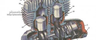
The working principle of a four-stroke scooter engine
The design of a four-stroke scooter engine, as well as its advantages.
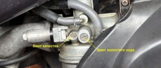
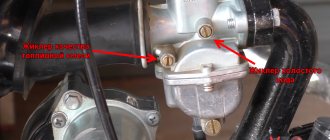
Scooter carburetor design
At first glance, a carburetor looks like a complex device, but with a little theory, it will be easier for you to adjust it. The first thing you need to know is at least the basics of the principle of operation of the carburetor and its main controls and adjustments. The throttle handle on the steering wheel is directly connected to the air damper and the metering needle attached to it. Air passing through the carburetor will pick up fuel from the fuel chamber.
Scooter crankshaft - device
After tuning other engine components (piston, commutator, etc.), the crankshaft must be replaced with a stronger (tuned) one. The fact is that when tuning the engine, the power and engine speed increase, which means the load on the crankshaft increases; a large load on a standard crankshaft is unacceptable! This can lead to wear and “killing” of the bearings, connecting rod, and the shaft itself, which means a complete engine overhaul.
Scooter chain drive device
The drive transmission consists of two sprockets - driving and driven. The drive sprocket is mounted on the centrifugal clutch drum. When the scooter engine is idling, the sprocket drum is not connected to the crankshaft. When the engine crankshaft speed increases, the clutch engages and torque goes to the clutch drum and drive sprocket. The driven sprocket is rigidly fixed to the rear wheel gearbox shaft.
Once upon a time, manual transmissions (from two to four stages) prevailed as transmissions for scooters, also called scooters. They were switched by rotating the left handlebar or, like a motorcycle, by a lever under the left foot. The main difference between a modern scooter and its predecessors and motorcycles is the absence of a manual gearbox. Its function is performed by an automatic transmission - a V-belt variator.
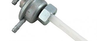
Automatic fuel tap
Automatic fuel tap (ATC) device
Ignition circuit components
The ignition system is an important element in the operation of the entire scooter. The formation of a spark and a precisely calculated impulse that ignites the fuel depend on it.
The scooter ignition circuit includes many components that are responsible for a specific job.
CDI ignition module
The first item in the list is the CDI module. This abbreviation stands for Capacitor Discharge Ignition - ignition from a capacitor discharge.
The switch module is made in a non-separable box, so if it fails, it is replaced with a new one. 5 wires are connected to it, distributed throughout the entire ignition circuit of the scooter.
The block is hidden inside the scooter, so getting to it is not easy. The plastic covers will have to be completely dismantled.
Ignition coil
The purpose of this component is a fast pulse of high voltage voltage based on a signal from the switch. It goes directly to the spark plug, where it is converted into a spark.
The coil is located on the right side of the Chinese scooter and is attached to its supporting structure. It is easy to recognize - it is made in the form of a plastic barrel. On the reverse side there is a thick wire connected. It is he who transfers the discharge according to the circuit from the transformer to the spark plug.
To protect against dirt and dust, the coil is placed in a rubber cover.
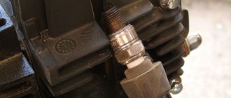
Spark plug
Its function is simple - to form a spark and ignite the mixture inside the cylinder. The scooter uses an A7TC spark plug.
Its position is hidden from view, but experienced owners know where to look for it. Having passed along the high-voltage wire, we reach the engine block and the spark plug cap.
The rubber seal protects the contact from accidental electrical breakdown. Remove with a little effort towards you. Do not pull the wire too hard - the cap may come off.
The spark plug is unscrewed with a socket wrench. After removal, you need to inspect the color of the contacts and their condition. An indicator of good engine performance is a brown tint without traces of soot. Deviation from the norm indicates a malfunction of the carburetor.
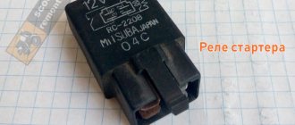
Starter
The device is used to make it easier to start a scooter engine, without using a kick pedal. The starter is located in the middle part of the moped, near the engine. To open it, you need to remove the decorative plastic.
The starter is connected through the starting relay, which is located on the scooter frame.
Fuel gauge and indicator
The sensor measures the amount of gasoline in the tank and signals the need to refuel. It is located in the tank itself and is connected by three wires.
The indicator is directly connected to the sensor. Both are powered by stabilized current from the rectifier. If problems are observed in the operation of the indicator, you should check the connection to the circuit.
Voltage is supplied only when the ignition switch is turned on.
Turns relay
The breaker is used to control the turn lights. When the button is closed, the relay produces current pulses with a frequency of 1 Hz.
The block is located under the instrument panel. To change the relay you need to remove the plastic protection.
Switching the circuit is not difficult. When turning right, voltage flows through the blue wire, which is responsible for the corresponding lamps. The left position of the switch shorts the gray bus to the orange one.
Duplicate lamps on the instrument panel are connected in parallel to the turns circuit lines. They signal that the lamps are on on a specific side of the scooter.
Sound signal
The purpose of the sound horn is clear to everyone. On the scooter it is located near the limiter relay.
The signal is powered by direct current through the ignition switch and is activated by a button on the handlebars of the moped. The component is non-separable, so if it fails, it is completely replaced.
General structure of the scooter
Any scooter owner should know how his vehicle works, because without such knowledge it is not only impossible to find out the cause of the malfunction, but also to eliminate it. Almost all equipment, no matter in which country or in which factory it was produced, has the same design for a scooter, so after examining and repairing one moped, you can easily troubleshoot any other.
Scooters are rightfully considered one of the most economical and unpretentious means of transportation. Ease of operation, low engine power and amazing maneuverability have made scooters one of the most popular types of equipment.
The structure of the scooter and its main components.
The structure of the scooter from the point of view of the organization of its main components can be viewed using the figures below.
The scooter is controlled, as a rule, by three elements: acceleration - 1) throttle; brake - 2) rear and 3) front. Of the two steering handles of the scooter, the gas handle is on the right. Brakes on both sides; rear and front - on the right or on the left, each manufacturer decides for himself how to arrange it.
In addition, the steering panel (so to speak) contains sensors, control buttons and switches (see picture). Usually like this: on the left - horn (1), turn signals (2), low/high beam switch (3); on the right is an electric starter (4), lights on/dimensions/off (5), and sometimes a stop button-switch (you can use it to turn off the engine without turning off the ignition, but you won’t start it until you turn it back on) (6). The number 7 indicates the throttle cable tension regulator. My scooter also has buttons to control the electronic clock. Sensors include a speedometer, sometimes a tachometer, a fuel level sensor; on two-stroke engines there is almost always an oil level sensor in the oil tank, light indicators, and turn signals. Also, scooters with hydraulic brakes usually have a “brake reservoir” (8) on the handlebars, which is used to determine the brake fluid level. I don’t think there’s any need to explain why there’s an engine in a scooter. The scooter can be equipped with a two-stroke or four-stroke engine - depending on this, the scooter device can be supplemented with additional components, for example, an oil pump for a two-stroke engine. (Well, diesel, rotary and jet engines are not yet installed on scooters. At least not commercially
Source
Electrics and electrical equipment of a scooter
Dedicated to all owners of Chinese scooters...
First, I would like to present a wiring diagram for a Chinese scooter.
Since all Chinese scooters are very similar, like Siamese twins, their electrical circuits are practically no different.
The diagram was found on the Internet and is, in my opinion, one of the most successful, since it shows the color of the connecting conductors. This greatly simplifies the diagram and makes it more comfortable to read.
(Click on the image to enlarge. The image will open in a new window).
It is worth noting that in the electrical circuit of a scooter, just like in any electronic circuit, there is a common wire . On a scooter, the common wire is the minus ( – ). In the diagram, the common wire is shown in green . If you look more closely, you will notice that it is connected to all the electrical equipment of the scooter: headlight ( 16 ), turn relay ( 24 ), instrument panel backlight lamp ( 15 ), indicator lamps ( 20 , 36 , 22 , 17 ), tachometer ( 18 ), fuel level sensor ( 14 ), horn ( 31 ), tail light/brake light ( 13 ), start relay ( 10 ) and other devices.
First, let's go over the main elements of the Chinese scooter circuit.
Egnition lock.
Ignition switch ( 12 ) or “Main switch”. The ignition switch is nothing more than a regular multi-position switch. Even though the ignition switch has 3 positions, the electrical circuit uses only 2.
When the key is in the first position, the red and black wires are connected. In this case, the voltage from the battery enters the electric circuit of the scooter, the scooter is ready to start. The fuel level indicator, tachometer, sound signal, turn relay, and ignition circuit are also ready for operation. They are supplied with power from the battery.
If the ignition switch malfunctions, it can be safely replaced with some kind of switch like a toggle switch. The toggle switch must be powerful enough, because the entire electrical circuit of the scooter is, in fact, switched through the ignition switch. Of course, you can do without a toggle switch if you limit yourself to short-circuiting the red and black wires, as the heroes of Hollywood action films once did.
1 is shorted to the housing (common wire). In this case, engine operation is blocked . Some scooter models have an engine stop button ( 27 ) to block the engine, which, like the ignition switch, connects the white- black and green (common, body) wires.
Generator.
The generator ( 4 ) produces alternating electric current to power all current consumers and charge the battery ( 6 ).
There are 5 wires coming from the generator. One of them is connected to a common wire (frame). The alternating voltage is removed from the white wire and supplied to the relay regulator for subsequent straightening and stabilization. The yellow wire removes voltage, which is used to power the low/high beam lamp, which is installed in the front fairing of the scooter.
Also in the design of the generator there is a so-called hall sensor . It is not electrically connected to the generator and there are 2 wires coming from it: white- green and red - black . The hall sensor is connected to the CDI ignition module ( 1 ).
Relay regulator.
Regulator relay ( 5 ). People may call it a “stabilizer”, “transistor”, “regulator”, “voltage regulator” or simply “relay”. All these definitions refer to one piece of hardware. This is what the relay regulator looks like.
The relay regulator on Chinese scooters is installed in the front part under a plastic fairing. The relay-regulator itself is attached to the metal base of the scooter in order to reduce the heating of the relay radiator during operation. This is what the relay regulator looks like on a scooter.
In the operation of a scooter, the relay regulator plays a very important role. The task of the relay regulator is to convert the alternating voltage from the generator into direct voltage and limit it to 13.5 - 14.8 volts. This is the voltage required to charge the battery.
The diagram and photo show that there are 4 wires coming from the relay-regulator. Green is the common wire. We have already talked about it. Red is the output of positive DC voltage 13.5 -14.8 volts.
The regulator receives alternating voltage from the generator through the white wire to the relay. Also connected to the regulator is yellow wire coming from the generator. It supplies the regulator with alternating voltage from the generator. Due to the electronic circuit of the regulator, the voltage on this wire is converted into a pulsating one, and is supplied to powerful current consumers - the low and high beam lamps, as well as the dashboard backlight lamps (there may be several of them).
The supply voltage of the lamps is not stabilized, but is limited by the relay regulator at a certain level (about 12V), since at high speeds the alternating voltage supplied from the generator exceeds the permissible limit. I think those who have had their dimensions burned out due to malfunctions of the relay-regulator know this.
Despite all its importance, the device of the relay regulator is quite primitive. If you pick apart the compound with which the printed circuit board is filled, you will find that the main relay is an electronic circuit consisting of a thyristor BT151-650R , a diode bridge on 1N4007 , a powerful diode 1N5408 , as well as several wiring elements: electrolytic capacitors, low-power SMD transistors, resistors and a zener diode.
Due to its primitive circuitry, the relay-regulator often fails. Read about how to check the voltage regulator here.