Changing the engine oil
In 2-stroke technology, the oil does not change, but is regularly poured into a separate tank and supplied by an oil pump to the carburetor, where it is mixed with the air-gasoline mixture and supplied to the engine.
The mixture lubricates the rotating and rubbing parts of the engine, burns and exits with exhaust gases into the exhaust pipe.
Oil tanks on scooters have different volumes - from 0.6 l to 1.3 l.
If you ride a motorcycle every day, then five liters of oil will be enough for a 2-stroke engine for the summer season.
The Oil lamp on the instrument panel indicates that the oil has dropped to the reserve level.
If the lamp lights up, it means that there is little oil left in the tank.
We'll have to capitalize on it. And this, you understand, is time-consuming and expensive repairs.
On 4-stroke 50 cc motorcycles, the oil is changed every 2 - 3 thousand km. During this mileage, fuel combustion substances accumulate in the oil and, as a result, it becomes dirty and thick, which changes its structure and properties.
If you drive together, transport cargo, that is, when the engine often works under heavy loads, then change the oil more often, after 1 - 1.5 thousand km.
Let's get down to business.
Start the scooter for 5 - 10 minutes. until the increased speed drops.
Place the motorcycle on the stand and turn off the engine.
Loosen the drain bolt.
Place a liter jar to drain the waste and unscrew the bolt completely.
Then unscrew the oil dipstick.
In 5 minutes, all the oil will flow out of the engine.
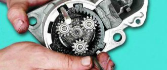
On a Honda Dio 56, there is a filter mesh under the oil drain cover. Wipe it well with a dry cloth and blow it or rinse it in gasoline.
On a Honda Dio 68, the oil filter mesh is located near the variator. The mesh also needs to be removed and washed.
Then reassemble everything in reverse order.
Fill the engine with oil through the dipstick. Its quantity depends on the motorcycle model and is indicated on the oil dipstick.
The level should be up to the top mark of the dipstick.
As you can see, the procedure is not complicated, but it requires care and will take 20–30 minutes. It's always difficult to start the first time, but then it will be business as usual for you.
Types of oil pumps, their design and operating principle
The pump's task is simple: pump motor oil in a circle. But there are several design options, since engineers all over the world continue to improve every, even the smallest, component of the car.
By design, pumps are rotary, gear (with external and internal gears) and vane (plate).
- The simplest gear oil pump consists of two gears with elongated teeth, installed in the working chamber so as to mesh. One of the gears is connected to the pump shaft, that is, it is driving, the second is driven, and rotates only due to engagement with the first. Engine oil is picked up by the gears during rotation and transferred to the opposite side, into the oil passages. This is a diagram of an external gear pump.
internal gear pump
Rotary
A vane pump is a working chamber into which a cylindrical rotor with slots is inserted. Flat slide plates are inserted into the slots and can move freely in these slots. When the rotor rotates, the space between it and the walls of the working chamber is divided into sectors. These sectors capture portions of liquid and transfer it to the discharge channel. The design of the vane pump allows you to adjust its performance by moving the stator and thus changing the volume of the working chamber.
Based on adaptability, a distinction is made between adjustable and unregulated types of pumps.
- The former have the ability to change performance depending on the engine’s current need for lubrication. Adjustable pumps ensure that the engine receives as much oil as it needs at all times.
The performance of unregulated pumps depends solely on the speed of rotation of the crankshaft.
For most cars, this is quite enough, unless you tune them for racing. To avoid creating too high pressure in the lubrication system when the engine gains power, unregulated pumps are equipped with a pressure reducing valve. It opens when the pressure reaches a critical point, and part of the oil goes back into the crankcase, that is, it serves to stabilize the pressure in the lubrication system. Pump drive types are electrical and mechanical.
- Electric oil pumps are quite rare as a design solution. They are used in turbocharged engines designed for high (sports) loads. The electric drive is needed to ensure that the pump continues to operate after the engine stops, cooling the hot turbine.
- Mechanical oil pumps driven by the engine crankshaft are used in most vehicles. The drive can be belt or gear, it depends on the design solution. The speed of the pump (and its productivity per unit time) depends on the load on the engine. This has its own logic: the faster the motor runs, the more it needs cooling, cleaning and lubrication.
Where is the oil pump located? If we talk about a lubrication system with a “wet” sump, that is, a conventional one, then in it the pump is located at the bottom, supplying oil to the system from the sump, from the bottom up. If this is an unregulated pump type, then when excess pressure is created, excess oil will drain through the pressure relief valve back into the crankcase. One pump is enough for a conventional engine.
A dry sump lubrication system, where a separate reservoir is provided for oil, is installed on powerful sports cars, which means it is designed for high loads. Two or even three oil pumps can be installed on such an engine, since at maximum speed such an engine requires both cooling and lubrication.
World of scooters.
Models, selection, tuning, repair and driving. >> Lubrication system. Engine. Contents :: Next >>
Lubrication system
Lubrication of engine parts is necessary to reduce friction between them (and therefore reduce wear) and remove heat. Parts in internal combustion engines are lubricated with motor oils. A thin oil film between the rubbing parts separates them from each other. A lack of oil in any place can cause local overheating, scuffing, and even welding of parts together.
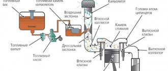
Two-stroke engine with separate lubrication system: 1 - oil tank; 2 - carburetor; 3 - throttle cable separator; 4 — throttle handle; 5 — oil supply control cable; 6 — plunger dosing pump; 7 - hose supplying oil to the inlet pipe. Diagram of a two-stroke engine oil pump drive.
Motor oils must be resistant to high temperatures combined with low viscosity at low temperatures, which is important for reliable starting of a cold engine. In addition, motor oils should not form carbon deposits during combustion and be aggressive towards rubber seals and plastic parts. Mineral (obtained from petroleum by distillation), synthetic and semi-synthetic oils are used to lubricate scooter engine parts. Synthetic oils do not have a petroleum base; due to effective anti-friction additives, the service life of the engine is increased (compared to mineral oils), and it is easier to start at low temperatures. Semi-synthetic oils are a mixture of high-quality petroleum and synthetic base components.
Lubrication of two-stroke engines
The easiest way to lubricate the rubbing parts of a two-stroke engine is to pre-mix a certain amount of oil with fuel in the tank (in a ratio of 1:25-1:50). This mixture circulates through the crank chamber, lubricating the crankshaft bearings, connecting rod and the cylinder bore along which the piston moves, with oil in the form of small droplets in the fuel-air mixture. Then the oil droplets burn in the cylinder along with the working mixture.
Oil pump of a two-stroke engine with the cover removed (arrow indicates the drive shaft).
The camshaft (or two shafts) is driven into rotation from the crankshaft by a chain or toothed belt; the drive uses a chain or belt tensioner and damper.
The power of modern serial 50 cc scooters reaches 5.5-7.5 liters. With. with a weight of 80-90 kg. In the 60s, 125-150 cc road motorcycles and scooters, which accelerated to 70-90 km/h, had this specific power.
Location of lubrication system components on a two-stroke engine: 1 - oil pump; 2 — inlet pipe; 3 - carburetor.
Until the mid-80s, this lubrication method was the most common in two-stroke engines. The amount of oil mixed into the fuel was chosen based on the need for maximum power, while this amount of oil for light loads was too much, and the engine smoked. This problem could be partially solved by using the so-called separate lubrication system installed on all modern scooters with two-stroke engines. In this system, a pump forces oil from a separate reservoir into the inlet pipe in the required quantity. In such systems, the oil supply at low loads is adjusted to a ratio of 1:200, which reduces exhaust smoke, reduces overall oil consumption and the level of soot formation in the combustion chamber.
The separate lubrication system uses a plunger type pump. It is driven from the left journal of the crankshaft through a worm gear. The oil is located in a special tank, which is installed above the pump and flows to it by gravity. The indicator lamp on the instrument panel lights up if there is little oil left in the reservoir. The amount of oil supplied to the intake pipe depends on the crankshaft speed. In some designs, there is another adjustment of its performance - from the position of the gas handle, for which the pump is connected to it with a separate cable (Honda scooters).
For Italian scooters with a fuel injection system for a Ditech two-stroke engine (more about this system below), the oil pump is electronically controlled, allowing the oil supply to be accurately matched to the engine load. At idle speed, it is enough to apply only one drop of oil every 5 minutes of operation.
Lubrication of four-stroke engines
The lubrication systems of these engines must have a mechanical oil pump located inside the crankcase. In addition to the pump, the lubrication system contains an oil filter, valves (return and pressure reducing) and lines in the form of channels (tubes and drillings in parts). The most common gear type oil pumps are those with internal or external gears. The pump shaft or direct drive gear is driven into rotation by the engine crankshaft.
Lubrication system of a four-stroke engine with a “wet” sump: 1 - oil pan; 2 — oil intake; 3 - oil pump; 4 - oil filter; 5 - safety valve.
After starting the engine, the pump sucks oil through the oil intake channel from the sump, which is located in the lower part of the crankcase. The oil is then captured by the gear teeth and pumped to the outlet cavity. Then, under excess pressure, it is supplied through the crankcase channels to the crankshaft bearings and timing parts.
Four-stroke engines use three methods of supplying oil to friction surfaces: under pressure, splashing and gravity. Most friction pairs are lubricated under pressure. The piston and its pin usually have enough oil sprayed from the holes in the lower head of the connecting rod or a separate nozzle aimed at the cylinder bore. Some friction pairs are lubricated by oil mist, which is formed when oil droplets splash on the moving parts of the crank mechanism. And finally, another group of parts is lubricated with oil flowing through special channels and gutters. The crankcase (sump) is usually an oil reservoir (called a wet sump). Having lubricated all the moving parts, the oil flows back into the sump, and then repeats its path again and again.
Dry sump four-stroke engine lubrication system.
Some scooters have a dry sump lubrication system. That is, they do not collect a lot of oil in the crankcase, and the draining oil is immediately pumped out by one of the pump sections into a separate oil tank, from where it is supplied under pressure to the friction surfaces by another pump section. The reservoir is usually located at the front of the scooter.
In an air-cooled engine, the oil can reach high temperatures. To prevent it from overheating and losing its lubricating properties, a radiator is usually built into the lubrication system, which is usually placed under the front trim of the scooter, connecting to the lubrication system with flexible hoses. The oil level in four-stroke engines is controlled using a dipstick (with minimum and maximum level marks) or through a special inspection hole or through a transparent “eye”. Operating the engine with a low oil level is unacceptable. If the oil level drops, it should be topped up, and if this happens too often, you should think about repairing the engine.
Gear oil pump with internal gears.
During operation, the oil becomes contaminated with wear products from engine parts and soot particles that have penetrated into the crank chamber through the gap between the piston and cylinder. To capture these particles, an oil filter located in the discharge line is used. In scooter engines it is replaceable and made of corrugated cardboard. This design is also called a cartridge-type paper filter. The filter usually includes a bypass valve. Under normal operating conditions, this valve is closed, but if the filter becomes so dirty that it stops passing oil, the valve will open and allow oil to bypass the filter. Naturally, it will not be cleaned, but at least it will continue to flow to the engine parts. In any case, increased wear is better than engine seizure due to oil starvation. Some engines are also equipped with an oil pressure limiting valve.
Despite the higher price, semi-synthetic and synthetic oils are increasingly used in scooters. Motor oils for two-stroke and four-stroke engines differ in their composition.
Paper type oil filter
Contents :: Next >>
Causes of oil pump failure
The reason why the oil pump has failed can be determined by diagnostics. There are at least 8 main oil pump faults. These include:
- Clogged oil pickup strainer. It is located at the inlet of the pump, and its function is to coarsely filter the engine oil. Like the system’s oil filter, it gradually becomes clogged with small debris and slag (often such slag is formed as a result of flushing the engine with various means).
- Malfunction of the oil pump pressure reducing valve. Usually the piston and spring included in its design fail.
- Wear of the inner surface of the pump housing, the so-called “mirror”. Occurs for natural reasons during engine operation.
- Wear of the working surfaces (blades, splines, axles) of the oil pump gears. It happens both over time of long operation and due to rare changes of (very thick) oil.
- Using dirty or unsuitable engine oil. The presence of debris in the oil can be for various reasons - careless installation of a pump or filter, use of low-quality lubricating fluid.
- Careless pump assembly. In particular, various debris was allowed to get into the oil or the pump was not assembled correctly.
- Drop in oil level in the engine crankcase. Under such conditions, the pump operates at excessive capacity, which causes it to overheat and may fail prematurely.
- Dirty oil filter. When the filter is very clogged, the pump has to make significant efforts to pump the oil. This leads to its wear and partial or complete failure.
Regardless of the reason that caused the partial failure of the oil pump, it is necessary to carry out a detailed check of it and, if necessary, make repairs or complete replacement.
Operation and causes of engine failure
Most often, two-stroke engines are found in motorcycles, boat engines, lawn mowers, chain saws and other devices that require the use of a lightweight and reliable engine. However, even such a simple engine can fail due to violation of operating rules.
To extend the service life and delay major repairs, you should properly break in a two-stroke boat or motorcycle engine. To do this, the proportion of oil mixed with gasoline should be slightly higher than that established for normal operation. With this mixture, let the engine run at partial power for several hours, which is equivalent to 500-1000 km for a scooter and motorcycle.
Nevertheless, due to exhaust toxicity, two-stroke engines are gradually being replaced by modern four-stroke engines. They continue to be used only where high power density is required with minimal weight and simplicity of design - motor vehicles, chainsaws and trimmers, model airplanes and much more.
Possible malfunctions and their symptoms
The resource of the unit is quite large and is about 100,000 kilometers.
How can you ensure that the oil pump does not fail prematurely? The condition for it to last the allotted time is regular replacement and topping up of oil, and periodic cleaning. In this case, only high-quality oil mixtures should be used. However, the device may fail. The following may be “symptoms” of a breakdown.
- Decrease or increase in operating oil pressure. This is indicated by a corresponding light on the vehicle’s dashboard.
- Increased oil consumption.
The following malfunctions may be the causes of such manifestations.
- The oil receiver screen is clogged. If dirt gets in there, it prevents the normal passage of fluid, resulting in the failure to provide the required pressure. The problem is solved by cleaning.
- Valve failure. If the pressure relief valve fails, no relief occurs when the pressure increases significantly. Eliminate the malfunction by replacing the failed part.
- Mechanical wear. Both the internal surface of the housing and the moving elements (gears, rotor, stator) are susceptible to it. If there is minor wear, you can replace the part that has become unusable. If it is significant, the only way to solve the problem is to completely replace the device with a new one.
- Poor quality oil. Some brands of lubricants do not have sufficient fluidity. As a result, problems may arise. The solution is to drain the old one and pump in new lubricant.
- Leak in the crankcase. Due to mechanical damage to the crankcase, lubricant may leak. In this case, the pressure drops and the oil pump begins to work more intensely. Solve the problem by eliminating the cause of the leak.
When is it necessary to change the transmission oil on a scooter?
Due to the fact that the scooter gearbox endures enormous loads, it must be maintained regularly. After all, after a certain mileage, the transmission oil becomes saturated with various metal particles, and a sediment also forms in it. All this leads to a deterioration in its physical condition and properties, which means that it will no longer provide the necessary protection, and the part will fail in the near future.
In principle, the frequency of replacement, as well as the class of oil, is indicated by the manufacturer, and it is these recommendations that should be followed. However, if we take an average, the frequency of this event should be about three thousand kilometers. What about running in equipment, then this operation should be carried out a little more often. The first time - after three hundred kilometers, the second - after a thousand, the third - after the mark has passed 2000 km, and then every 3000 km or once a year if the equipment is not used very often.
On a new scooter, the transmission fluid is changed more often.
Complication of design
Using the example of a 2.5 liter diesel engine from VW, you can see how much more complex the operation of the lubrication system of a modern engine has become. Let's look at the purpose of each of the elements.
- Two-stage internal gear type oil pump. Installed in the oil pan.
- Oil pressure regulating valve. Using a solenoid valve, the ECU (Engine Control Module) directs oil to different channels, thereby switching the operating modes of the oil pump. When regulating performance, the engine load, coolant temperature, crankshaft speed and signals from the automatic transmission are taken into account. When a control signal is applied, the valve opens, allowing oil to flow into the channels of the first stage (the pressure in the system is about 1.8 atmospheres). In the absence of a control “mass”, the return spring returns the valve to its original position, changes the direction of oil flow, raising the pressure in the system to 3.3-4 Atm.
Changing the performance makes it possible to reduce the mechanical losses spent on lubrication and cooling of the engine’s rubbing pairs. This solution increases the overall efficiency of engines, reducing the amount of harmful emissions.
- Check valves in return lines. They allow lubricant to flow in only one direction and prevent complete drainage of oil from the channels after the engine is stopped. Filled channels allow you to avoid oil starvation in the first seconds after starting the engine.
- Safety valve. Opens during a cold start when excessive pressure develops in the system.
- Small circuit valve. Triggers when the filter element is clogged, opening the way for oil to bypass the filter.
- Oil cooler. Oil and coolant circulate through the heat exchanger housing.
- The cooler helps maintain the thermal balance of the engine and prevents oil overheating.
- Oil injector valve. It opens when the design pressure is reached in the system, opening the line to the injectors.
- Oil nozzle. Sprays oil onto the piston crown, removing heat from it.
- Pressure reducing valve. Triggers when excessive pressure is reached in the system, protecting the cylinder head from excess oil.
Classification and selection basics
Today, three main classifiers are used in the world to describe the properties and scope of application of two-stroke oils:
Let us consider only the current standards in force today. There is no point in reviewing outdated and out-of-use classifications, since they are almost impossible to find on sale today.
According to SAE, two types of motor oils are common today: TD and TC-W3. The first type, TD, is suitable for most two-stroke engines in use today. Lubricants marked TC-W3 are intended for outboard internal combustion engines. The main difference between these lubricants is their high environmental friendliness. There are no significant differences in performance characteristics.
According to JASO, today you can find oils marked FB, FC and FD. Quality and performance increase as the second letter moves away from the beginning of the alphabet. Lubricants marked FB are suitable for low-load engines without specific requirements.
| Test parameters for JASO and ISO | ||||
| ISO | — | E.G.B. | E.G.C. | EGD |
| JASO | F.A. | FB | F.C. | — |
| Lubrication properties | 90 min | 95 min | 95 min | 95 min |
| Torque index | 98 min | 98 min | 98 min | 98 min |
| Cleaning properties | 80 min | 85 min | 95 min | 125 min |
| Deposits on the piston skirt | — | 85 min | 90 min | 95 min |
| Smokiness | 40 min | 45 min | 85 min | 85 min |
| Deposits in the exhaust system | 30 min | 45 min | 90 min | 90 min |
Category FC has reduced smoke emission. FD, in addition to reduced smoke, has increased cleaning properties.
The ISO classification is based on the Japanese JASO. However, several additional levels of testing have been introduced here, which every certified oil must pass.
Similar to JASO, there are three classes:
In the case of ISO classification, the first two classes additionally carry out tests for the cleanliness of the pistons after use. The last class must pass a detergency test.
Standards for two-stroke engine oils - video
Chainsaw oil pump - purpose
The idea of using an automatic oil pump to lubricate parts is not new; using increased oil pressure to penetrate hard-to-reach cavities has been around for a long time. The oil pump is successfully used in internal combustion engines when processing parts using an oil emulsion, so the idea of lubrication of the working part of a chainsaw using an oil pump has become widespread and used.
A saw chain, consisting of connecting links and links with cutting teeth, when working when heated, requires overcoming a large friction force, both at the joints of the links and in the form of wood.
In addition, the working guide bar along which the chain moves must also be constantly lubricated from the attachment point to the gear at the end.
The chainsaw oil pump is designed to ensure effective lubrication of these two elements.
Changing the oil in the gearbox
At the very bottom of the engine, on the left side in the direction of travel, we are looking for the drain and filler plug of the gearbox. The filler plug is located on the side or on top, and the drain plug is always at the bottom.
Place a container under the drain plug and unscrew both plugs.
We wait about ten minutes until the old oil drains from the gearbox.
Let's take the oil. I take a liter canister, it’s cheaper and lasts for about 10 replacements. If you change oil infrequently, buy a special tube of branded oil for scooter gearboxes. There is more than enough of it for one replacement, and without unnecessary headaches, pump it into the filler hole using a special spout.
For those who prefer to save money, there is only one thing left to do: pump oil into the gearbox in small portions using a regular syringe. Unfortunately, there is no other way to fill the gearbox with oil because the filler hole is too small.
Checking the oil level in the gearbox
We pump oil into the filler hole, also known as the control hole, until it begins to flow out of it. As soon as the oil starts to flow, stop pouring, wait a couple of minutes for the excess to drain, and tighten the plug.
Source
Oil pump, what is it? Concept and purpose of an oil pump
A car oil pump is a device that creates pressure on the lubricant in the system, so that it flows to the moving elements of the internal combustion engine. Pressure is necessary to supply lubricant (oil) to those engine elements that require forced lubrication, for example the camshaft located in the cylinder head, that is, much higher than the oil tank and without the pressure created by the oil pump, lubricant will not reach it
The car oil pump is driven by the crankshaft or through the drive shaft from the camshaft
According to the nature of control, they are divided into two types: adjustable and unregulated
- Adjustable - thanks to the ability to regulate performance, it creates stable pressure in the system
- Unregulated - constant lubricant pressure is maintained due to the presence and operation of a special pressure reducing valve
Depending on the design, they are also divided into:
1. Rotary type - pressure is created due to the rotor blades
2. Gear type - the oil receives pressure due to the operation of gears.
They in turn are divided into:
- external gears - when two gears are located next to each other,
- internal gears, when one gear is located inside another.
The difference in gear placement does not affect performance, but does affect the size of the device. Due to the fact that the gears are located in each other, much less metal is required to accommodate them, and therefore the internal gear is smaller in overall dimensions
Features of two-stroke oil - ISO standard
One of the global classifiers when selecting lubricants for internal combustion engines is the design of the motor. Based on the number of individual completed operations, so-called strokes, modern piston engines are divided into:
Almost all motorcycles and cars, as well as other heavier equipment, are equipped with four-stroke engines. Two-stroke engines have occupied a niche among small-displacement and cross-country motorcycles, various portable tools, light water transport, as well as in several other industries.
In this article we will look at the features of two-stroke oil, and also briefly examine some important points of application and the basis of choice.
Troubleshooting and repair of a removed element
Let's look at how to test a removed oil pump. The check consists of visual inspection, measurements and comparison of the measurement result with the nominal dimensions.
Unscrew the oil receiver cap together with the pressure reducing valve. It is worth making an effort so that the spring thrust washer does not get lost
Next, note that some bolts will be smaller than others. This bolt should then snap back into place.
Use a caliper to measure the spring. At rest, it should be at least 38 millimeters in length. Then remove the cover, which will have marks from the wear of the gears. If the scoring is deep, then the oil pump has a lot of wear. The cover can be repaired - its plane should be leveled.
Next, remove the drive gear and visually check the condition of its teeth. If there are abrasions and burrs on the teeth, this indicates a lot of wear. The driven gear should also be checked. The main thing about it is the hole in which the fixation axis is located.
Then check the walls of the device housing and the axis of the driven gear. Potholes, grooves, and various defects indicate that debris has entered the working area inside the pump.
What to do if the lamp is on?
As we said earlier, a special indicator lamp will indicate low pressure. What are our actions if we find ourselves in such a situation? First of all, you need to turn off the engine. Next, open the hood and check the oil level. It also happens that the lamp lights up due to its low level. If the dipstick is normal, you need to look deeper for problems. But this must be done in a garage or service center. It is better to get to the repair site by tow truck.
When is a burning lamp normal? It only appears like this after a cold start. In the first seconds, the pump cannot yet generate the required pressure. But if the motor has been running for 30-50 seconds, this clearly indicates a problem.
Useful tips
It is quite obvious that even such a reliable solution as an oil pump has a limited service life. Of course, in order to increase the service life, it is necessary to take into account the reasons for oil pump breakdowns discussed above. Understanding the reasons allows you to avoid such troubles.
First, you should always change the oil and oil filter regularly, and also monitor the engine oil level and its condition. If it is clear that the oil has become very black, its viscosity has changed, and problems arise with oil pressure in different operating modes of the internal combustion engine, you should check the lubrication, as well as the functionality of the engine oil pump.
If it is necessary to inspect and replace the oil pump, you must also replace the engine oil and oil filter, as well as thoroughly clean the engine crankcase, check the condition of the pressure relief valve and oil intake. It is also recommended to completely flush the lubrication system before adding fresh oil.
Oil pump. Theory and practice.
Oil pump
can be called a hydraulic mechanism (machine), which, by analogy with a hydraulic pump, converts the mechanical energy of the mover (muscular energy of humans or animals for hand pumps) into the energy of the flow of oil fluid and serves to transport and create pressure of the oil fraction and their mixtures.
Oil pumps have different classifications according to their application:
To create pressure in lubrication systems of various mechanisms;
For pumping (transporting) oil-containing liquids from/to containers/containers, as well as for pumping and pumping oil from/to containers and mechanism components;
For household use.
Oil pumps are also classified according to the nature of their controllability and are divided into:
Adjustable, when control over the main parameters of the pump is carried out through automatic control units or mechanical regulators of the main parameters of the pump and propulsion unit;
Uncontrolled, when the operation of the pump is controlled, but its parameters cannot be changed by external influence.
Classification of oil pumps by design differences:
- Gear-type oil pumps, which in turn are divided into 2 types - an external gear pump (gear around a gear) and an internal gear pump (gear in a gear). This is the joint work of the drive and driven gears, when oil enters the pump through the suction channel, is captured by the gears and is pumped into the system through the discharge pipe. Their performance is directly dependent on the speed of the engine shaft (mechanical impact);
1. Driven gear;
2. Suction channel;
3. Drive gear;
4. Drive shaft;
5. Discharge channel;
6. Driven gear axis.
The oil pump is a rotary type, which in its housing design combines the work of 2 rotors (internal - driving and external - driven). The oil is captured by the blades of both rotors and enters the pipeline system under pressure.
1. Suction cavity
3. External rotor
4. Discharge cavity
5. Drive shaft
6. Inner rotor
This type of oil pump can be regulated or unregulated. Adjustable rotary oil pumps operate on the principle: when the frequency of the engine drive shaft increases, the pump consumes a larger volume of oil and the pressure in the system drops, the spring mechanism is activated and shifts the position of the stator relative to the movement of the pump rotor, thereby increasing the volume of the pump cavity, which leads to an increase in oil pump performance and vice versa.
A - Discharge side B - Suction side
Piston oil pumps are mechanisms in which the principle of suction of oil-containing liquid and its expulsion occurs due to the reciprocating movement of the piston (pistons) (plunger) in the housing cylinder with at least 2 check valves.
Vane (vane) oil pumps are adjustable units that have an eccentricity adjustment system (installation of the rotor shaft in the volume of the oil cavity). The operating principle of the pump is based on changing the volume of the suction and discharge cavities due to the non-coaxial rotation of the rotor in the pump chamber.
Impeller oil pumps, in which the movement (transportation) of the oil-containing fraction is carried out due to the impeller blades, which create a difference in fluid pressure at the inlet and outlet of the pump chamber. The impeller performs reciprocating movements and two pairs of valves (inlet and outlet). When the impeller moves, the pumped liquid moves from the suction cavity to the discharge cavity. The valve system prevents fluid flow in the opposite direction;
Rotary-type oil pumps, in which the movement of an oil-containing substance is carried out by 2 shafts with a specific cross-sectional profile. According to the principle of operation, the rotary lobe pump is positive displacement. When the driving and driven rotors rotate, a vacuum is created on the inlet side, causing fluid to move from the inlet side to the outlet side. At the outlet, when the cams engage, fluid is squeezed into the system. The pump consists of the following main parts and assemblies:
— drive and driven shafts with a rotor, rolling bearings and gear installed on each of them;
Scooter engine design
According to the good old tradition of our site, we will study the design of the engine using a real example. We won’t go through much trouble finding a victim as an example, but we’ll take the most ordinary four-stroke engine made in China - we’ll cut it up and at the same time study its internal contents.
Moreover, the engines of modern scooters have a very similar design and a single layout diagram, so the engine that we will consider today in its design and design will practically not differ in any way from its counterparts from Japan or Europe. Except for minor details.
Victim: an ordinary Chinese NONAME with some unrealistically jumbled numerical index: JL1P39QMB-2.
This engine has several important or not very important components of mechanisms and systems without which its full operation is impossible. As the article progresses, we will consider each component mechanism or system in more detail.
Supply system
The power system of this engine consists of two main elements: a carburetor and an air cleaner; the power system also includes additional elements in the form of pipes, manifolds, fuel taps and pipes.
The location of the power system elements on other engine models may differ significantly, and some elements may be completely absent, for example, a carburetor. On modern engines it is no longer installed due to design imperfections.
The principle of operation of the power system
Under the influence of vacuum - created by the piston in the combustion chamber - atmospheric air first rushes into the inlet of the air cleaner where it is cleaned of dust and then the already purified air enters the carburetor through the connecting pipe.
In the carburetor, the air is saturated with gasoline vapor to the required proportion and then in the form of a combustible mixture through the intake manifold - through the open intake valve - it goes straight into the combustion chamber where the combustion process occurs.
Cooling system
The cooling system installed on this engine is an air-forced cooling system. These types of cooling systems are very simple, cheap to manufacture, reliable, do not require maintenance and almost never break down, but are ineffective.
Cooling system design
The cooling system, in our case of the forced-air type, is designed not simply, but very simply, one might even say that it is outrageously simple... Its design is based on the most ordinary centrifugal fan, or, to put it correctly: a fan impeller, which is bolted to the generator rotor rigidly connected to the crankshaft.
After starting the engine, the fan impeller begins to rotate, creating a flow of air, which, to increase the efficiency of the cooling system, with the help of special casings, moves in the right direction to blow the most heated parts of the engine: the cylinder head and the cylinder itself.
The fan impeller is hidden behind the cooling shroud located on the right side of the engine.
Cooling casings through which the air forced by the fan moves along the cooled engine parts - evenly blowing and then - through special channels in the cooling casings - the hot air is discharged outside.
The most heated engine parts: the cylinder head and the cylinder have developed fins, which allows the cooling area to be increased several times and thereby improve the efficiency of the cooling system.
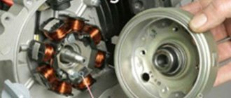
Generator
The generator installed on this engine is a flywheel type alternating current generator with excitation from permanent magnets. The generator consists of two main elements: a rotor and a stator; also, to ensure timely formation of a spark on the spark plug, an additional module in the form of a magnetic induction sensor has been introduced into the generator.
It will be possible to get to the generator stator only after removing the fan impeller and rotor from the crankshaft journal.
Lubrication system
The lubrication system installed on this engine is a combined type lubrication system: some parts are lubricated under pressure, and the other part by splashing or through “oil mist”, which is formed during engine operation.
The lubrication system is one of the most important engine systems - without which its operation is impossible. Any malfunction in this system ends for the engine either in the destruction of parts or in a complete “wedge” of the engine, and most often both.
It is also worth considering that the lubrication system is an additional element of the engine cooling system.
The lubrication system consists of two main parts: the oil pump and its drive. On this engine, the oil pump is driven by a gear directly from the engine crankshaft. On other engine models, the oil pump can be driven by a chain.
Also, to ensure the full operation of the lubrication system, there are several additional modules in its design: check valves, filters, oil lines, radiators, probes, pressure sensors and other devices.
Main elements of the lubrication system
Oil pump removed
Lubrication system operation
During operation of the oil pump - the engine oil located inside the engine crankcase under the influence of vacuum - created by the oil pump begins to be drawn into the receiving hole of the oil filter and then through the oil channel enters the receiving hole of the oil pump housing.
In the oil pump housing, the engine oil is given pressure under the influence of which it rushes through the oil channel into the main oil line.
The main line, in turn, is divided into two separate channels, through one of which the engine oil, under pressure through a channel in the cylinder, enters the cylinder head - lubricating and cooling the parts of the gas distribution mechanism, and through the second channel, the engine oil enters a special cavity located on the crankshaft cheek.
In the cavity on the crankshaft cheek - under the influence of the centrifugal force arising during rotation of the crankshaft - engine oil rushes into a special channel located in the pin of the lower connecting rod head - carrying out forced lubrication of the bearing of the lower connecting rod head.
Oil channels for the lubrication system of cylinder head parts
All other engine parts are lubricated by oil spray or oil mist.
crank mechanism
The crank mechanism consists of two main parts - the piston and the crankshaft. The piston absorbs the energy of expanding gases in the combustion chamber of the cylinder head - performing reciprocating movements, and the crankshaft, through a connecting rod rigidly connected to the piston by means of a piston pin, converts the reciprocating movements of the piston into rotational movement of the crankshaft.
Main parts of the crank mechanism
Gas distribution mechanism
The gas distribution mechanism installed on this engine is of type: ONS and consists of several parts: intake and exhaust valves, camshaft, rocker arms, drive chain, drive chain tensioner, drive chain guides and other parts.
The gas distribution mechanism ensures the timely supply of the working mixture to the combustion chamber and the removal of exhaust gases from it.
Operation of the gas distribution mechanism
During engine operation, the camshaft, driven by a chain from the crankshaft with the help of cams located on its surface, alternately opens the intake and exhaust valves.
To prevent the timing chain from jumping off the sprockets, the chain is kept in constant tension using a special chain tensioner, and is limited from moving off the axis by two guides: upper and lower.
The cam located on the working surface of the camshaft at a certain moment approaches the rocker arm support and then, under the action of the cam, the rocker arm rotates on its axis and acts on the valve stem with its second support.
Camshaft position when valve is closed
Camshaft position when valve is open
Timing drive parts
Electric engine starting mechanism
The electric starting mechanism consists of two main parts: an electric starter and a mechanism for interacting the starter with the scooter engine. In our case, the role of the interaction mechanism is performed by the bendix; on other models of scooters, a starter overrunning clutch can be installed instead of the bendix.
Each of these interaction mechanisms has a number of advantages and a number of disadvantages, but in any case, the starter overrunning clutch is preferable to Bendix in its performance properties.
Operation of the electric start mechanism
After pressing the “Start” button, the output shaft of the electric starter begins to intensively rotate the Bendix primary gear. When a certain speed is reached - the primary gear - the mechanism inside the Bendix is activated - the secondary gear engages with the teeth of the outer pulley of the variator - a direct connection is formed between the starter and the engine, the engine begins to rotate and it starts.
After starting, the Bendix secondary gear automatically disengages and the connection between the starter and the engine is broken.
Engine transmission
The transmission installed on this engine is an automatic type of transmission - completely freeing the driver from the need to change gears, or control the clutch, or perform any other actions.
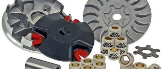
The function of transmitting torque from the engine to the rear gearbox and then to the rear wheel of the scooter is carried out by an automatic mechanical-type variator, which is in rigid connection with an automatic centrifugal clutch.
Torque transmission in CVT transmission types of scooters is carried out using a V-belt.
Main transmission parts
Scooter transmission operation
After starting the engine, the front pulley of the variator is rigidly connected to the crankshaft and begins to rotate - transferring a certain part of its rotation with the help of a belt to the second pulley of the variator.
Depending on the engine speed and the settings of the variator, the number of revolutions transmitted to the rear pulley of the variator may be different.
The automatic clutch, which is in rigid connection with the rear pulley of the variator, upon reaching a certain speed of the rear pulley of the variator, is activated, a direct connection is formed between the engine and the rear wheel of the scooter, due to which the starting and further movement of the scooter occurs.
After a further increase in engine speed, the variator, depending on the speed of the scooter and engine speed, in fully automatic mode changes the transmission ratio to the optimal value.
Design of a car engine lubrication system
Engine lubrication system
The main task of the lubrication system is to provide an oil film on the contacting moving parts of a car engine. This helps reduce power loss and wear of the power unit. In addition, the oil supplied by the system is used in hydraulic tensioners and in valve timing control mechanisms. In the general design of the car, the lubrication system is integrated into the engine structure and consists of the following elements:
- Filler neck - oil is filled or topped up through it.
- The oil pan is the lower part of the engine housing filled with oil. For proper engine operation, the amount of working fluid in the sump must be at a certain level, which is measured using various sensors and devices (dipstick). Not only excess oil flowing from the engine mechanisms accumulates in the sump, but also contaminants formed during operation. Also on the pallet there is a drain hole and a plug in the form of a bolt with a washer. When changing the oil, the plug must be replaced along with the washer.
- Oil intake - is a structure consisting of a pipe running from the sump to the pump and a coarse filter.
- – sucks up lubricant using an oil intake from the sump and supplies it to the system. It starts and stops simultaneously with the engine. The drive can be a crankshaft, a camshaft or an auxiliary drive shaft. As a rule, two types of pumps are used in cars for pumping oil: gear (more popular) and rotary.
- Oil filter. It is installed at the pump inlet and is designed to clean the working fluid from chips and carbon deposits. There are two types - dismountable (when the filter is dirty, only the filter element is replaced) and non-dismountable (the entire filter is replaced).
- Oil radiator. Since the working fluid in the lubrication system also cools, it passes through a radiator to reduce its own temperature. The latter, in turn, is cooled by the cooling system fluid.
- Lines and channels - oil moves through them from one unit to another.
- Oil nozzles. Used to supply oil to cylinder walls and pistons.
- Pressure, temperature and oil level sensors - send signals to the electronic engine control unit, transmitting data on the state of the lubrication system and engine operating mode.
- Valves (bypass and pressure reducing valves). Allows you to automate oil pressure control and control its supply to the system. Such valves are mounted near the leading elements of the system (pump, main engine components, filter).
Some engine models may not have sensors or a radiator. In this case, the oil is cooled directly in the oil pan.
Features of a two-stroke engine
Two-stroke internal combustion engines have some differences in operating principle relative to four-stroke ones. This type of engine, just like a four-stroke engine, includes a crankshaft, connecting rod, piston and cylinder.
However, the gas distribution mechanism here is implemented not with the help of a camshaft and valves, but with a set of so-called windows for various purposes.
In general, for the simplest models of these internal combustion engines, there are three windows:
The purge and outlet port is opened and closed by the piston body. The piston in two-stroke internal combustion engines has a uniform elongated skirt. The purge window can be closed with a special valve or, like the other windows, with a piston.
There are two windows on the fuel supply side. The inlet, which is located below, and the purge, which is located above. Exhaust gases exit through the exhaust window, which is located on the opposite side.
The fuel-air mixture from the carburetor or injection system enters the chamber in front of the intake port. The intake port does not have a direct connection with the cylinder. It opens access to the hollow space under the piston chamber, where the crankshaft with connecting rod is located.
The crank chamber is isolated from the environment. When the piston rises, a vacuum is created in the chamber. And closer to top dead center, the fuel-air mixture is sucked into the space under the piston.
As the piston moves downwards, towards the end of the power stroke, the exhaust window first opens, through which exhaust gases are released into the atmosphere under pressure.
Next, a purge window opens, through which fresh mixture is pumped into the combustion chamber. The fresh mixture pushes out the exhaust gases completely. The cycle repeats.
There are other designs with more complex organization of circulation of the fuel-air mixture and exhaust gases. However, the design in question is basic, and it fully describes the essence of the operation of two-stroke engines.
The piston, cylinder walls and connecting rod bushings are lubricated by oil dissolved in the fuel. That is, there is no oil in the crankcase of a two-stroke engine, specifically in the crank chamber.
Two-stroke engine oil is added only to fuel. Lubrication in its traditional sense is found only in the gearbox and sometimes in the compartment with the clutch discs. It is these operational features that determine the properties of two-stroke oil.