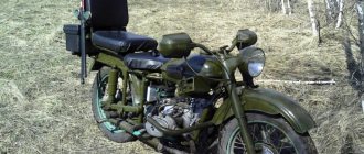
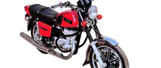
The Ural is equipped with a very good, even by today’s standards, engine, the volume of which is 750 “cubes” and has a power of 40 horsepower. Despite the fact that the motorcycle weighs more than 200 kilograms, it has excellent dynamics and picks up speed well. It is also equipped with hydraulic brakes and has a military-style design, which gives this motorcycle a special exclusivity, for which it is appreciated by many fans.
Similar articles
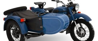
New versions of this motorcycle are distinguished by high reliability and a special retro style, which is so rarely seen on modern models, unless, of course, we are talking about “cafe racers”. But the Ural is a motorcycle from a different “test”; its history goes back more than 70 years, so today it is almost impossible to buy a modernized and tuned Ural in good condition. Therefore, tuning comes to the aid of lovers of this motorcycle, which is done with their own hands or by specialists and includes several serious modifications, after which the motorcycle can truly be considered an urban exclusive.
Carburetor design
The carburetor for the Ural motorcycle is a horizontal device designed to prepare the air-fuel mixture. The float chamber is located in the center of the assembly. The mechanism is equipped with a flat throttle valve with vertical stroke, two dosage systems - the main one, the idle one. They shape the volume and quality of the mixture.
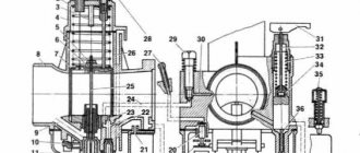
The starting device is located separately, consisting of three main blocks, Fig. 2:
- building 8;
- chamber with float 38;
- cover 4.
Rice. 2. Schematic representation of the carburetor for 63. 1 - Fitting with lock nut; 2 - Throttle spring; 3 - Throttle lift limiter; 4 - Housing cover; 5 - Lock nut; 6 - Dosing needle bar; 7 - Throttle; 8 - Housing; 9-Air channel of the sprayer; 10 - Float lever axis; 11 - Spray body; 12 - Sprayer; 13 - Float chamber cover; 14 - Main fuel jet; 15 — Idle fuel jet; 16 - Lock washer; 17 — Channel for supplying the fuel mixture from the starting device; 18 - Float; 19 — Stop for adjusting the fuel level; 20 - Fuel valve; 21 - Drainage hole; 22 - Emulsion hole: 23 - Transition hole; 24 — The air channel of the jet is idle, running; 25 Dosing needle; 26 - Air channel of the float chamber; 27 — Fuel receiving fitting; 28 — Idle speed adjustment screw; 29 — Mixture quality adjustment screw; 30 - Air channel; 31 - Starting lever; 32 - Rod; 33 - Spring; 34 - Starter plunger; 35 — Float drowner; 36 - Plunger needle; 37 — Fuel jet of the starting device; 38 - Float chamber.
The float chamber communicates with the atmosphere through the vertical outer channel of the housing 26. The top cover of the chamber has a drainage hole 21. The carburetor of the Ural motorcycle is equipped with a lever float mechanism consisting of two floats 18. Both products have the shape of rectangles, connected together by a common lever made of the innovative material caprolactam as one piece.
Axle 10, pressed into the lever, presses the structure with floats against the two columns of the housing. The brass fuel valve 20 visually resembles a needle. There is an elastic washer on top of the cone. It is practically eternal, almost not subject to wear. Thanks to it, the Ural carburetor always has a stable level of gasoline in the float chamber. The valve has a groove at the bottom that connects it to the float. Therefore, it never gets stuck in the guide channel.
Injector for Ural/Dnepr 650cc
So, we offer a retrofit kit for electronic injection for boxer motorcycles. In particular, the kit is compatible with motorcycles “Ural”, “Dnepr/MT” 650 cm3 and “Ural” 750 cm3. We tried to make sure that retrofitting a motorcycle with electronic injection would take no more than 3-4 hours without significantly changing the design of the motorcycle or engine. At the same time, given the variety of options for boosting engines, it is possible to individually configure the control unit for each individual engine.
We have developed components that allow you to succinctly retrofit the boxer with electronic injection.
- Throttle assembly
- Fuel distributor
- Control block
- Wiring harness
Throttle assembly
Throttle valve bodies with a 32mm bore have been developed. They are installed in standard places instead of carburetors. The left and right are mirrored, while the throttle position sensor (TPS) is installed only on the left valve, and the idle air controls (IAC) and injectors are on the left and right. The fastening to the cylinder is standard with studs. The throttle cable does not require modification. All fastening elements are made of stainless steel or galvanized.
Fuel distributor
The fuel distributor allows you to reduce the number of fuel lines during retrofitting and also acts as a pressure regulator housing. Fuel from the tank flows through the fuel distributor to the pump and fine filter, then returns back and is supplied to the left and right fuel injectors. Excess fuel is discharged into the tank through a special line in the fuel distributor.
Control block
The block provides for the connection of the following sensors and actuators:
- Hall sensor (optical)
- Throttle Position Sensor (TPS)
- Absolute pressure sensor (MAP) (built into the unit)
- Intake air temperature sensor (IAT)
- Engine temperature sensor (ETS)
- Oxygen sensor (broadband or narrowband lambda probe)
- Idle air control (IAC)
- Two LEDs (built into the unit)
Contents of delivery
- Throttle assembly left Throttle body left
- BOSCH fuel injector
- Throttle Position Sensor BOSCH
- Idle air control (OMEGA group)
- Throttle body right
- Control unit Hall sensor
- Hall sensor modulator/shutter
- BOSCH pressure regulator
You can buy it here m2boxer.by
Chopper from the Urals
Choppers became popular in post-war America. In order to somehow stand out among the faceless masses, the mobilized Americans came up with the following. They decided to remove everything unnecessary from their motorcycles.
It all started with the massive wings. Most motorcyclists have completely given up on these parts. To reduce the weight of the motorcycle, the tank was made minimally capacious. They also abandoned the double seat. On motorcycles they left a single seat on springs. The handlebars for choppers were made high.
You can make a chopper from the Urals. To do this, you need to find a spoked and narrow rear wheel. The tires should be size 130-150. No need for a larger one. The wheel size will determine where the rear of the frame needs to be changed. Two welded v-frames will replace the standard swingarm.
For a seat, a standard “frog” from a rare model, for example, the K-750, would look great. It is imperative to raise the “spine” part of the frame. The part of the frame that goes down to the engine from the steering column is padded with spacers to make it look longer.
With a telescopic fork, the feathers can be cooked to make them longer, or they can be completely remade. Extended stays will require the installation of an additional crossbar. This will give the structure the necessary rigidity. The front wheel must be larger than the standard one, but thin. Front brakes are not needed.
Mirrors and turn signals are removed - they are not used in choppers. Muffler - only with direct flow. The footpegs need to be moved forward - this is not discussed. Thus, having completed all the necessary work, you will turn your Ural into a stunning chopper.
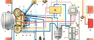
Motorcycle ignition systems are designed to ignite the working mixture in the engine cylinders. On the Ural motorcycle the system is constantly being modernized. Mechanical ignition has its disadvantages and significant ones. The Ekaterinburg company proposed electronic ignition for the Ural motorcycle, which was accepted by the manufacturer.
MY MOTORCYCLE
All modern motorcycle manufacturers are transferring their equipment from carburetor power systems to injection ones. “Why is my Ural worse?” - Vladimir Polyakov from Sochi thought and created an injection system on his Voyage. Yes, such that any plant will be jealous: fuel consumption by the engine has been reduced to three liters per 100 km.
1. The microprocessor and fuel pump are located in the seat tank
2.Instead of the usual carburetors - Italian plumbing.
He was tired of carburetors - they constantly required adjustments, synchronization, the engine started poorly, kept an uncertain idle speed... And in a secret Sochi laboratory (at Vladimir’s house), a certain device was formed from a bunch of wires, hoses and plumbing parts and was implanted into the Irbit Ural motorcycle.
The operation of the engine is controlled by an electronic “brain” based on a PIC16F84 microprocessor. The injection and ignition algorithm is “hardwired” into it (our lab manager wrote the programs for it himself). But not simple ones, but with the ability to adjust the mixture composition and ignition timing. To select the desired program, there are three buttons under the gas tank, and on the steering wheel there is a liquid crystal display, which displays all the information about everything happening in the engine.
1.The flow meter is installed between the air filter and the throttle valve
2. The generator now has a “dry” drive.
But in order for the control system to issue commands accurately, it needs reliable information from the sensors. This is a crankshaft position sensor, a variable resistor that monitors the position of the throttle valve (borrowed from some ancient Opel), and a mass flow meter for the air sucked into the engine power system.
The ignition system of the Ural motorcycle consists of a two-spark coil from the Oka and a VAZ switch. But the switch does not have the function of changing the ignition timing depending on the speed and load on the engine, therefore it is entrusted with the function of a power switch that controls the “bobbin”. The signal comes to the input of the switch from the microprocessor, and it, according to the selected program, determines the moment at which the spark should “strike”.
The coil took the place of the generator. For what? And then, so that you can install an energy source in front of the engine and get rid of oil leaks from under the oil seal and the ever-howling drive gears. Now the on-board power station is rotated by a toothed belt from an electric planer. The pulley is installed on the camshaft shank, which was empty due to the lack of a standard ignition system.
- The crankshaft position sensor is located in the crankcase inspection window.
And under the gas tank of the Ural motorcycle there is a fuel pressure regulator and program adjustment buttons.
The fuel system is the pinnacle of genius of the entire development. At first glance, you might think that it was made in Italy - this idea is suggested by the inscriptions “Made in Italy” on the intake pipes. In fact, everything is much more prosaic; it’s just that when creating the injection system, parts from Italian plumbing were at hand. These shiny pipes became a second home for VAZ injectors (their performance turned out to be suitable for the cubic capacity of the cylinders). I had to tinker while choosing the angle of installation of the injectors, because the fuel in the spray pattern should fall into the air stream and not settle on the walls of the intake tract. The air is “managed” by one throttle valve, in front of which there is a mass air flow sensor. The fuel pump, located under the saddle, and the vacuum fuel pressure regulator, which took the place of the gas tap, were also borrowed from the “ten”.
What is the result? The engine always starts with half a turn, runs perfectly smoothly and responds adequately to movements of the throttle. Fuel consumption in the most economical mode allows Vladimir to travel from Sochi to Taman and back on one tank of gasoline, in other words, the Ural Voyage motorcycle “eats” about 3 liters of gasoline per “hundred”.
This is far from an ordinary result - without extraordinary technical erudition, it is unlikely that anything would have happened. But there is one more result of this work: Sochi resident Vladimir rubbed his nose in the hands of the designers of the Irbit Motor Plant.
Author Lev GARYAEV, photo by Dmitry TYURIN
Source MOTO magazine No. 5 2007
Adjusting the main carburetor systems in the Urals
Adjustment of carburetors on a Ural motorcycle is carried out after checking and adjusting the gaps between the spark plug electrodes, breaker contacts, valve stems, and the ends of the rocker arms. Each of the two carburetors is separately adjustable. It is necessary to begin adjusting the carburetor in the Urals after measuring the gap between the tip of the cable sheath and the fitting, which should be 2-3 mm.
Rice. 3a. The main elements of the carburetor: 1 - main air path: 2 - throttle valve; 3 - subsidizing haze; 4 — air nozzle; 5 - sprayer; 6 — air channel; 7 - well; 8 — main fuel jet; 9 — float chamber (central location).
Rice. 3b. Fuel corrector: 1 — air inlet channel: 2 — spool; 3 — spool needle; 4 — fuel jet: 5 — sprayer; 6 — output emulsion channel; 7 — spool return spring; 8 — corrector control cable.
If the gap does not correspond to the specified size, the union locknut is loosened. Turn to the right or left to set the required gap. After this, the fitting is re-locked with a lock nut and the carburetor of the Ural motorcycle is adjusted. By turning off the warm engine at a minimum engine speed without load, the basic settings are made. The idle system is adjusted for each of the two mechanisms separately. The Ural carburetor is adjusted with the second cylinder turned off.
Idle adjustment
By rotating screw 28, the crankshaft speed is set to the minimum stable engine speed. Screw 29 is slowly unscrewed gradually until the motor begins to malfunction. It also gradually, slowly twists until a calm, stable speed is achieved. Once again, use screw 28 to reduce the opening angle of the throttle valve until the minimum speed is reached.
At the same time, screw 29 adjusts the saturation of the mixture. Such operations are repeated until the minimum stable engine crankshaft speed is obtained. The carburetor of the Ural motorcycle is adjusted in the same way for the second cylinder. The test is carried out by sharply opening and closing the throttle. In this case, you must sharply turn the throttle towards yourself and release it to its original position.
Operating modes
Modes of medium loads are characterized by the position of the needle relative to the throttle. Adjustment is carried out by choosing its most optimal position. The settings must be repeated when seasonal conditions change (winter-summer), during the running-in of new vehicles, in order to increase engine power. In this case, the dosing needle 25 moves along the thread relative to the bar 6. The locknut 5 is loosened.
When screwed into the bar, the needle rises in relation to the nozzle hole. The mixture becomes richer. When unscrewing, the mixture becomes leaner. One revolution of the needle moves 0.5 mm. The quality of the adjustment is checked by sharply turning the throttle knob. The loud pops that the carburetor makes on a Ural motorcycle indicate that the mixture needs to be enriched. To do this, the needle rises.
When operating motorcycles, owners often wonder which carburetors are best to install on a Ural motorcycle. Now Chinese carburetors are widespread in the Urals. There are some good examples among them. Foreign-made Solex and Weber models performed well in operation. However, their prices are higher than domestic ones.
What carburetors should I put on the Ural IMZ motorcycle? In my opinion, a Russian-made K63 carburetor would be good for the Urals. This is a trouble-free mechanism, the professional adjustment of which allows it to last for several decades. Every 5 thousand km it is recommended to clean it, blow it out, and rinse it.
The jets must be washed with acetone. The parts are wiped with rags or soft vinyl. The throttle should be installed after servicing with the cutout facing the air filter. Regular maintenance will ensure long-term trouble-free operation of the K63 model.
Hi all. Continuation of the topic: Opposite injector. How it all started. Part 1 I started my collective farm with a mixing unit for air and fuel. The cover of the plumbing filter was removed and the mesh was removed. In addition, I also took ¾ by ¾ couplings, meaning that the injectors would live in them. I screwed a rubber adapter to the head for jikov carburetors. The plumbing filter fit perfectly there (side up as in the photo) But it was still necessary to cut off the edges intended for turning with a key. I decided to supply air the same way as in the Urals (oppozit.ru/article70001.html) through the filter tube where the filter element itself lived. There was a third hole left for the injector and fuel supply. I decided this: I’ll fill the coupling with aluminum, drill holes and the nozzle will fit like a glove! But not everything is so simple, oh not everything... Then the nightmare began. For some reason, I decided that I was an experienced foundry worker and that everything would work out for me right away. As it turns out, you can’t melt aluminum on the knee, but if you pour it in, you’ll end up with complete crap. The only way to melt aluminum was achieved by melting aluminum in a pouring mold (in fact, the crucible is the coupling), heating it on a gas stove and heating it additionally with a gas burner. Plus, we needed another jar on top so that the heat wouldn’t escape. A few photos below show how I suffered during the manufacturing process of this, as it later turned out, useless part.
I did what I wanted. It worked the nth time, the holes were drilled and the injectors were installed. Next I decided to make an air supply. But a joke emerged. The thread on the filter cover does not fit anything standard at all. And this means looking for a pipe and a die and cutting it somehow somewhere. Of course, I don’t have such healthy dies. The carving idea was dropped. BUT a new one has arisen. You can solder (I also don’t have the ability to weld copper and brass) a piece of copper tube. Again, a pipe was selected at a plumbing store, or rather a coupling for connecting copper water pipes by soldering. The tube was suitable in diameter, but soldering with lead-tin solder meant that ultimately this design would fail, and it’s good if at the time of testing in the garage, but what if on the road. Therefore, after consulting with colleagues at work, I realized I wanted copper-phosphorus solder. This solder is used to solder copper pipes where high pressures must be maintained. I couldn’t find such solder in my city (probably I didn’t look well), so they brought me two rods from St. Petersburg from the Chip-Dip store. Then the process was repeated as with casting. I just warmed up the plumbing filter and somehow poked it with solder. Oddly enough, it turned out very well! The solder wetted both copper and brass. The design turned out to be rigid and reliable. The remaining modifications to the plumbing filter were not so interesting, there was the removal of ribs for installation in a rubber adapter (like on Jikov carburetors), and the removal of part of the brass from inside the filter so that nothing would interfere with the injector to spray fuel. Looking ahead, I will say that the design has undergone minor changes. I abandoned aluminum-filled couplings , but more on that later.
As I already said, I didn’t want to saw the flywheel at all, so I decided to turn on the smart one and hack January. I’ll say right away that the idea failed! I decided that I have a camshaft, so I’ll hook a marker disk with (60-2)*2 number of teeth there and install an optical sensor. Let me explain. The camshaft rotates 2 times slower than the crankshaft, which means that in 1 revolution of the crankshaft half a revolution of the camshaft will occur. This means that you need to make, conditionally, two marker disks, one after the other. A hacksaw and a piece of iron solved this issue.
It was very interesting to integrate into the January scheme. After reading the datasheet on the microcircuits, it became clear where to send the signal, which was done. Everything was even checked by rotating a drill and a diagnostic program, the engine speed was displayed. As I said, this idea did not work, although, theoretically, it was viable. Subsequently, I sawed the flywheel, but more on that later.
In fact, all the time, other work on studying the injector was going on in parallel. Especially the software and hardware part. I soldered the first k-line adapter (k-line adapter on two transistors) on a circuit board, on wires, it worked and I learned how to download and upload firmware, as well as diagnose the unit, well, like diagnostics, look at the numbers. Subsequently, I ordered an OBD2 connector from China and a k-line interface chip, and a USB-UART-K-LINE converter was assembled from trash, which I subsequently used. I didn’t disassemble the braid of wires, I just used it, it’s very convenient. Moving further on the electrical part, I turned on the smart one again. The fact is that the standard ignition module has two switches and two coils, and everything is in a single housing for cylinders 1-4 and 2-3. This categorically did not suit me, because I only needed half, this is cylinders 1-4. Moreover, there were many articles about how these modules are doing well. Before the work on installing the injector, I had a Saruman ignition. I decided that I needed to leave everything as is, just convert the signal from January into a signal understandable for an ordinary VAZ switch. Saruman's spark occurs when the signal wire touches the ground. In January it's the opposite. Sparking when the voltage on the signal wire jumps by +5V. Shit question, the transistor will solve everything. A circuit was assembled using 1 transistor and a pair of resistors to invert the January signal. Subsequently it worked, but incorrectly . Looking ahead, I will say that I installed the ignition under the name “God's Spark”, and I carry a spare switch with me. I didn’t want to cut off the connector for connecting the ignition module, so, having obtained the faulty ignition module, I sawed off the mating part from it, soldered the wires and filled it with epoxy. It turned out like this:
Fuel supply and air supply became a problem for me. I'll start with the fuel supply. I wanted to use mainly VAZ spare parts, so I bought a standard VAZ pump. And he immediately fell into a puddle, because it is designed to live in a tank, but I need a suspended one. As I later found out, I need a pump from the Volga. Actually, I later installed such a pump. But I tried to trick the regular VAZ driver like this: Never do that. Everything flowed. It didn’t work out to seal it, so in general I was angry and indignant. It's my own fault. The issue with the fuel rail was also not immediately resolved. At first, the crazy idea of soldering copper water pipes hit my head. But it was dropped due to concerns that the structure would fall apart. Although there is an injection Ural with just such a ramp (search in Google for “Opposed injector made of shit and sticks”). Having turned the VAZ fuel rail with a pressure regulator in my hands, I realized that it was compact and could well suit my tasks. I plugged 4 standard holes for the injectors. I plugged them like this: I screwed an 8-gauge nut onto the bolt, sawed it off so that a piece of the bolt the thickness of the nut remained in the nut; I peeled off the edges and it turned out, roughly speaking, to be a cylinder. I put these 4 cylinders with sealant in the holes. Cover it with sealant on top and press it with the corners through the rubber gaskets. I drilled two new holes, cut the threads and screwed in fittings made from 8mm studs. A 4mm hole is drilled along the stud. The photo makes it more or less clear how it turned out:
You can see in the photo that I made the supply to the injectors from the fuel rail using copper pipes. The injectors are also equipped with fittings. The injector fitting is an 8 mm coupling (coupling means such a long nut), sanded to a cylinder shape. The same drilled 8 mm pin is screwed into the coupling. The nozzle and fitting are connected by a piece of rubber hose. It took me a long time to solve the problem with the air supply. At first I wanted to use the standard VAZ receiver. The fact that he would not fit into the motorcycle became obvious when I began to push him against the frame. It was very big and uncomfortable.
Then I revised the idea with the receiver and made it compact from a housing for electronic equipment (radio-electronic equipment). In the receiver body I installed a small fitting made of a copper tube for vacuum (for installing DBP and for the fuel pressure regulator). On a copper tube, 4 mm, a standard M4 thread is cut with a die. And the fitting is ready. I removed the air from the receiver using a stainless steel sanitary sink drain. The connection between the drain and the receiver is made using the same adapters for the jikov carburetor.
Closer to spring 2021, I had all the parts and components to install an injector on a motorcycle. But summer is motorcycle season and you need to ride, but you don’t want to sit in the garage. I started my first attempt at installing the injector closer to the fall. A few photos below are the first fittings and installation of knots. And also local adjustment:
Some of the nodes have changed, some details too. Looking ahead, I will say that I removed the mass air flow sensor (MAF). I installed an air temperature sensor (ATS) in its body. I installed an absolute pressure sensor (MAP), brought it into the atmosphere and tuned the engine to the throttle.
Additional engine modifications
In addition to the above methods of tuning a Ural motorcycle, there are several more secrets. It is possible to install a crankshaft from the K 750 on the Ural engine, which will increase the cylinder stroke to 78mm.
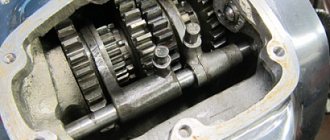
Thus, it is possible to significantly increase the working volume of the Ural engine. It's quite difficult to find, but it's worth it. Another problem with the motorcycle is the tight response to the throttle and slow acceleration. The reason for this is that the flywheel is too heavy, the weight of which is designed for riding with a stroller and for transporting heavy objects.
According to the drawing, it is possible to reduce its weight by a couple of kilograms. Due to the weight reduction, the inertia of the crankshaft will decrease, and the acceleration dynamics will significantly increase. To fully realize the power on the road, the gears of the gearbox must be replaced with 9 or 10 pairs. In conclusion, we would like to note that tuning the Ural motorcycle engine is justified only for racing purposes; for everyday use, such an engine will have a short resource and significant fuel consumption.
Ignition
Following an increase in power and replacement of pistons, it is advisable to replace the spark plugs. Spark plugs A20 DV and A17 DV from Zhiguli are suitable for Ural. Some craftsmen install an additional candle. This increases engine power at high speeds, reduces consumption and can become a replacement for boost. But work will have to be done to develop an independent spark generation system. At the same time, the air filter is changed, which reduces friction losses during intake.
If the engine is old, then it is advisable to replace the carburetor and install an injector. This can be done with your own hands or with some help. Tuning the Ural motorcycle can be done using injection spare parts from the VAZ "Ten"
Ural Hercules - factory Ural tricycle
The Irbit Motorcycle Plant has released a three-wheeled modification in its model range for transporting cargo up to 500 kg. The model is called “Hercules” and moves well both on city roads and off-road. The sides of the tricycle are also removable and this allows it not to be limited in the size of the cargo it transports. Hercules is a truck that does not require a category “C” license.
Technical characteristics of the Hercules tricycle:
- Dimensions: 335x150x115 cm
- Ground clearance: 185 mm
- Weight: 500 kg
- Fuel tank capacity: 19 l
- Maximum speed: 70 km/h
- Engine capacity: 750 cc
- Power: 45 hp
- Engine type: opposed 4-stroke with two cylinders
- Generator: 500 W
- Electrical: 12 V
- Transmission: 4-speed, with reverse gear
- Tires: 6.45 and 13 inches