I’m working further and this is an essay and probably a reminder for me and for those who will also disassemble everything... In short, if you want to put the motorcycle in complete order with your own hands (in my case it’s still the engine and gearbox, I just haven’t gotten around to the rest)
To begin with (if you are a city person and you have the opportunity to spend 50+ thousand wooden ones on a hobby, then we go to the market if you don’t have a tool) You will need a 36 socket (long and better impact) and a wrench (I bought one for trucks with inch square and transition to 1/2 inch for torque wrenches)
You will need pullers (especially 2-arm and 3-arm pullers (large for 2-arm gears and flywheel removal)
You will also need WITHOUT OPTIONS BUY OR FIND THIS SCREWDRIVER (otherwise the work will stop until you get this gadget) Impact rotary screwdriver (any manufacturer) 2 pry bars (medium) 2 pry bars (small) 1-2 blunt chisels of different sizes and also this puller (you need will be in order to then press out the bearing race
In principle, let's start work and I'll tell you where to start
THE MOST IMPORTANT THING CONCERNES SAFETY AND FIRE SAFETY
On the Dnieper, 2 halves of the tank are connected by a hose that runs under the frame and when lifting the tank from its place, this damn hose is removed and fuel begins to flow, I almost had a big boom with a shish kebab from me as it doused me significantly. So be very careful. 1. Drain the oil from the engine and gearbox. 2. We hang up the rear wheel or the pendulum to remove it (I’ll answer the stupid question of what it is... it can’t be removed right away) the brake cable goes to the rear wheel and if you look at it, there is a rod that is held on by a cotter pin that you just need to remove (saw off, saw off, bite off in general, get rid of it) 3. Having unscrewed and removed the cardan, remove the generator and disconnect all the wires from the engine and gearbox
Here comes the moment of understanding how much strength you have and whether anyone can help you, if not and you are ready to scratch the motorcycle frame, then move on, if not, then read the same thing, but at the moment of jacking the engine is held by a couple of people
The engine hangs on 2 studs that pass through the engine from below, depending on the wear, I recommend cleaning it, lubricating it with water and heating it to 150-300 degrees. Then the nuts will come off with a bang; we knock out the studs from the side of the stroller if necessary)))
Before dismantling the studs, walk around in a circle and make sure that everything has been removed!!!
4. If you 1 then unscrew 3 NUTS and ONE BOLT WHICH IS SCREWED ON THE SIDE OF THE CYLINDER AND ON THE SIDE WHERE THE 3 NUTS ARE LOCATED, you can see that the stud is broken!!! keep this in mind!!!
Basically, we just remove the engine.
Stages of working with a removed engine!!!
1. Unscrew the pan and get ready to see a bunch of goon that will either flow as jellied meat!!!
2. Remove the front part of the engine carefully. 3. Remove the gear using a puller and remove the centrifuge and oil pump!!! otherwise you won’t be able to remove the guitar later. 4. The next step is to remove all the gears and look for the presence of the mark!!! in order to then set the timing gears, the mark is something that looks like hitting two gears with a chisel in one place (you can’t make a mistake, but if not, do it yourself) and for one gear you will need a 2-armed puller and for the other a 3-armed puller and another one thing is VERY VERY IMPORTANT , the center of the puller should rest against anything but not the shafts (you can screw bolts onto the shafts and then if you don’t do this, the shafts will flare!!! and may burst!!!
5. You’re probably already itching to try the impact a screwdriver, but early now it’s time to take a rubber hammer, a flat regular impact screwdriver and two small prybars))) and by tapping on the fastening with a rubber hammer, we turn it so that we can slip a prybar under the ledge on one side and the other, and by pressing on the ends of the prybars we try to pull it out camshaft (usually it’s easy for everyone, for some it’s simply removed with your fingers, which is even worse) 6. Let’s move on, now we need to remove the guitar (remove the keys in advance!!! I hope you’ve already done this)
Now, using the pry bars, we remove the guitar!!! Very carefully, it is fragile but can come off like this for me and this is not uncommon as I understand it
Removing the bearing is very easy; in the photo below you can see two factory holes that are needed for these purposes; old valves are ideal for knocking out; only the tip of the valve needs to be reduced; it is better to use a sharpener (reduce the diameter to the narrowest part, as for crackers, and to a depth of 2-2.5 cm) then it will be enough to knock out the bearing. By lightly tapping the valve, we knock out the bearing, changing the pressing points, one then the other.
Next, a smoke break, since you’ve been pretty tired of having to take a smoke break and drink a glass, especially since you’ll need it later)))
Flywheel
To remove this thing you will need an impact head and a handle for the possible use of a pipe + a person holding the engine 1 piece. We take Kuzkin’s mother’s impact screwdriver and disassemble the clutch, removing everything, we see a 36 bolt and a lock washer.
Down with the washer, the bolt has a normal thread; if you look at it, unscrew it to the LEFT SIDE .
After unscrewing, remove the flywheel and see the oil seal with a retaining ring!!! Now you will need the puller that was in the beginning. After removing the retaining ring, we heat the seat with a hair dryer and slowly knock out the bearing race. Since all the bearings I install are Japanese, I will install them like this.
That's all for now, next there will be a part of the report on engine assembly and a report on the box, I confess I haven't started yet, I don't have time.
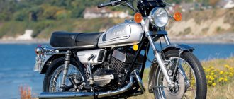
RESTORATION OF THE DNPR ENGINE
Engine repair during normal operation of a motorcycle, as a rule, becomes necessary after several tens of thousands of kilometers, when power drops noticeably due to decreased compression in the cylinders, oil consumption increases, mufflers smoke more, knocks and noises appear. With sufficient experience, you can judge the condition of the engine by the noise of its operation or by external signs. If any irregularities suddenly appear, it is advisable to establish the cause of the malfunction before disassembling the engine, so as not to touch unnecessary components. because in this case the connections of worn-in pairs and seals are disrupted. (Behind the Wheel, No. 2, 1984)
When disassembling the engine, as well as other mechanisms (partial or complete), it is recommended to mark the parts so that, after checking, the usable and slightly worn ones can be put back in their places.
In a motorcycle engine, piston rings are among the parts that wear out quickly. They are made from special cast iron.
The oil scraper rings of the engines of all Dnepr and Ural motorcycles are interchangeable, the ring height is 5-0.015 mm. Compression rings are not interchangeable: ring 7201217-01 (K750M) has a height of 3 mm, and 6101217 (MT) - 2.5 mm. The designations and dimensions of the piston rings are given in Table 1.
| Color marking and connecting rod head diameter, mm | Color marking and finger diameter, mm | |||
| red 36.000-35.996 (36.020-6.016) | white 35,996-35,992 (36,016-36,012) | green 35,992-35,998 (36,012-36,008) | black 35,998-35,984 (36,008-36,004) | |
| group number and roller diameter, mm | ||||
| red 50.012 - 50.009 | 4 6,996 — 6,998 | 3 6,998 — 7,000 | 2 7,000 — 7,002 | 1 7,002 — 7,004 |
| white 50.009 – 50.006 | 4 6,996 — 6,998 | 3 6,998 — 7,000 | 2 7,000 — 7,002 | 1 7,002 — 7,004 |
| green 50.006 - 50.003 | 5 6,994 -6,996 | 4 6,996 — 6,998 | 3 6,998 — 7,000 | 2 7,000 — 7,002 |
| black 50,003 – 50,000 | 6 6,992 — 6,994 | 5 6,994 — 6,996 | 4 6,996 — 6,998 | 3 6,998 — 7,000 |
| In brackets are dimensions for Irbit engines | ||||
Signs of ring failure are smoking from the mufflers, increased oil consumption (more than 300 cm3 per 100 kilometers), decreased compression, malfunction of the ventilation system (increased oil release through the breather tube is possible). In this case, it is necessary to remove the cylinder heads, and then check the condition of the piston group parts.
When the rings wear out, the gap in their locks increases. The maximum permissible is 3 mm. To measure it, the rings are removed from the piston, marking their location. Then the ring is inserted into the cylinder, its position is aligned with the piston and the gap in the lock is measured with a feeler gauge. Worn ones are replaced for the first time with rings of normal size, and then, when the cylinder is worn out and it is bored out, rings and a piston of a repair size are installed. Before installation, the new ring is inserted into the cylinder and the gap in the lock is checked, which should be in the range from 0.20 to 0.6 mm.
Before installing the cylinder in place, lubricate its mirror and piston skirt with engine oil, spread the rings so that their joints are located at an angle of 120° to one another. When putting the cylinder on the piston, the rings are compressed with a clamp, which can easily be made from tin.
A sign of piston wear is a dull metallic knock in the cylinder area, especially noticeable after starting a cold engine.
The right and left pistons in both engines are the same, cast from heat-resistant aluminum alloy KS-245. The cross-section of the skirt is oval. and longitudinally - a conical shape. In the MT engine, the axis of the hole for the piston pin is shifted from the plane of symmetry by 1.5 mm.
To ensure correct installation of the piston into the cylinder, there is an arrow on its bottom, which must be facing forward during installation, that is, towards the centrifuge. In this case, when looking at the MT engine from behind, the pin in the piston of the right cylinder is shifted down, and in the piston of the left cylinder it is shifted up. The holes for the piston pin are divided into four groups by diameter (every 0.0025 mm) and marked with paint on the boss (Table 2).
| Table 1 | ||||
| Rings | Size | Ring catalog number | Outer diameter, mm | |
| K-650, MT9, MT10, MT10-36, “Ural” | K750M, "Dnepr-12" | |||
| Compression | normal 1st repair 2nd repair | 6101217 6101217-Р1 6101217-Р2 | 7201217-01 7201217-01-Р1 7201217-01-Р2 | 78 +0.021 increased by 0.2 increased by 0.5 |
| Oil scraper | normal 1st repair 2nd repair | 7201218-01 7201218-01-Р1 7201218-01-Р2 | 78 +0.021 increased by 0.2 increased by 0.5 | |
| table 2 | |||
| Color coding | Finger diameter, mm | Diameter of holes in the piston, mm | Diameter of hole in connecting rod, mm |
| White | 21,0000 — 20,9975 | 20,9930 — 20,9905 | 21,0070 — 21,0045 |
| Black | 20,9975 — 20,9950 | 20,9905 — 20,9880 | 21,0045 — 21,0020 |
| Red | 20,9950 — 20,9925 | 20,9880 — 20,9855 | 21,0020 — 20,9995 |
| Green | 20,9925 — 20,9900 | 20,9825 — 20,9830 | 20,9995 — 20,9970 |
| Table 3 | |||
| Cylinder and piston size | Cylinder diameter, mm | Piston catalog number for MT (in brackets - for K750M) | Piston diameter for MT (in brackets - for K750M), mm |
| Normal | 78,000 — 78,04 | MT801237 (72H01237-A) | 77,98 — 77,94 (77.96 — 77.92) |
| 1st repair | 78,20 — 78,24 | MT801237-Р1 (72H01237-Р1) | 78.18 — 78.14 (78.15 — 78.11) |
| 2nd repair | 78,50 — 78,54 | MT801237-P2 (72H01237-P2) | 78.48 — 78.44 (78.45 — 78.41) |
| Table 4 | |||
| Size | Amount of repair reduction, mm | Crankpin diameter, mm | Catalog number of the set of inserts |
| Normal | — -0,05 | 47,975 — 48,000 | 407-1004058-A2 407-1004058-A2P1 |
| 1st repair | — 0,25 | 47,735 — 47,750 | 407-1004058-A2P2 |
| 2nd repair | -0,50 | 47,475 — 47,500 | 407-1004058-A2P4 |
| 3rd repair | -0,75 | 47,225 — 47,250 | 407-1004058-A2P5 |
| 4th repair | -1,00 | 46,975 — 47,000 | 407-1004058-A2P6 |
According to the outer diameter (measured under the oil scraper ring), the pistons are sorted through 0.01 mm into four groups. The size of the piston group is stamped on the outside of the bottom with the numbers: “77.95”. "77.96." “77.97”, “77.98” for the MT engine and “77.93”. "77.94", "77.95". “77.96” for K750M. In addition, pistons are divided into groups by weight, which coincides with the color index of the piston pin hole.
Approximately, we can assume that the service life of the piston is equal to the wear time of two sets of rings in it. The piston wears out the grooves for the rings (especially the top one), the walls of the pin holes and the skirt.
The piston must be replaced if the gap between the cylinder bore and the largest diameter of the skirt (in the plane perpendicular to the axis of the pin, below the groove for the oil scraper ring) exceeds 0.25 mm. The gap can be measured with a feeler gauge with the piston positioned lower in the cylinder.
If the piston is normal, and only the grooves of the upper compression rings are worn out (the end gap is more than 0.15 mm), you can install a ring from the K750M engine on the MT engine. having previously ground it in height, taking into account the provision of an end gap in the range of 0.04–0.07 mm for the upper ring and 0.025–0.055 mm for the lower one.
Usually, when replacing pistons for the first time, when the cylinders are still slightly worn, to reduce the gap between the mirror and the skirt, you can install a “normal” piston, but with a larger skirt diameter. For example, if the cylinder diameter of an MT engine of group “1” (78.01–78.00 mm) during operation increased to 78.04–78.03 (which corresponds to group “4”), then the “77.95” piston in it should be replaced with a piston with designation "77.98". In this case, the required gap of 0.05–0.07 mm will be restored. In the K750 engine, pistons are selected to ensure a clearance of 0.07-0.09 mm.
Pistons are selected not only by skirt diameter, but also by weight in order to maintain engine balance. The difference in the weight of the pistons should not exceed 4 g. The piston pin is made of 12ХНЗА steel, cemented and heat-treated to a hardness of HRC 5v-63. It rotates freely in the upper head of the connecting rod with a clearance of 0.0045-0.0095, but is pressed into the piston bosses with an interference fit of 0.0045-0.0095 mm. According to the outer diameter, the fingers are divided into four groups every 0.0025 mm and marked with paint on the inner surface (see Table 2).
Gaps of more than 0.01 mm in the connection of the pin with the piston and more than 0.03 mm in the connection of the pin with the connecting rod can cause distinct sharp knocks and intense wear of parts when changing the engine operating mode. To eliminate these phenomena, the piston pin should be replaced, observing the required markings and its fit in the piston and connecting rod according to table. 2. When installing the finger, the piston is heated to 80-100 ° C in the oven or in boiling water; Before assembly, the pin is lightly lubricated with engine oil, then the holes in the piston and the upper head of the connecting rod are aligned and the pin is driven into them with light blows of a hammer through a mandrel. The fit of a lubricated piston pin into the upper head of the connecting rod is considered normal when it easily fits into the hole, but does not fall out if its axis is positioned vertically.
You can remove the finger without heating the piston, but you must use a special device. If it is not there, you can heat the piston bottom with a blowtorch through a metal sheet and, using a mandrel made of soft metal (copper or aluminum), knock out the pin, as shown in Fig. 1.
The cylinders of the MT engine are the same and interchangeable. The sleeve is cast from special cast iron and is integrally connected to an aluminum alloy jacket. The hardness of the sleeve is HB 207-255. K750M cylinders are cast from special cast iron, their hardness is HB 207-255. The left and right are not interchangeable, since they differ in the position of the intake and exhaust valves.
The cylinders are divided into four groups according to their internal diameter at intervals of 0.01 mm. The size of the MT group is stamped in the lower part of the cylinder jacket (near the flange) on the side of the rod casings with the numbers “1”, “2”, “Z” and “4”, which correspond to diameters 78.01-78.00; 78.02 - 78.01; 78.03 - 78.02 and 78.04 - 78.03 mm. For the K750M, the group index is stamped on the plane of the valve box.
The cylinder must be replaced or bored to the nearest repair size of the piston if the wear of the upper part of the mirror is 0.15-0.20 mm. When the cylinder becomes tapered (wider at the top) and oval, it is no longer possible to restore normal compression by installing a new piston and rings.
Cylinder wear is determined by measuring its diameter with a bore indicator in three zones located at distances of 15, 50 and 90 mm from the upper end of the cylinder in the connecting rod swing plane and in a plane perpendicular to it.
The worn cylinder is bored and honed to fit the repair diameter of the pistons (increased by 0.2 or 0.5 mm). After processing, the ovality and taper of the mirror should be no more than 0.015 mm, the cleanliness of the processing should not be lower than class 9, the runout of the seating end relative to the mirror should not be more than 0.05 mm, the misalignment of the mirror and the outer surface of the cylinder mating with the engine crankcase should not be more than 0.08 mm . The piston is selected so that the installation gap between the largest diameter of its skirt and the cylinder for MT is 0.05-0.07 mm, for K750M - 0.07-0.09 mm. When installing a new piston into the cylinder, you must be guided by the information given in table. 3.
The connecting rod and its cover for the MT engine are stamped from 40X steel, hardness - HB 217-266. The lower connecting rod caps are not interchangeable, so each one must be put in its place during assembly. When installing connecting rods on the crankshaft, the protrusions in their middle part should be directed outward relative to the middle cheek of the shaft. The lower head has liners that are interchangeable with the connecting rod liners of the Moskvich-408 engine. A bronze bushing made from BrOTsS-4-4-2.5-PT-1.5 tape is pressed into the upper head. the hole of which is made with great precision. According to its diameter, the connecting rods are divided into four groups (every 0.0025 mm) and marked at the head with a color index (see Table 2).
The assembled connecting rods are divided by weight into seven groups (every 5 g) and marked with paint. Connecting rods with single-color markings are installed on the crankshaft. The nuts of the connecting rod bolts are tightened to a torque of 3.2-3.6 kgf/m. The cotter pin should fit tightly into the bolt hole. Used cotter pins must not be used. Possible defects of the connecting rod are wear of the bushing under the piston pin, bending and twisting of the connecting rod body.
The diameter of the sleeve can be measured with an indicator bore gauge. If the gap between the bushing and piston pin is more than 0.03 mm, the bushing should be replaced. To do this, you need to make a new bushing from tin bronze BrOFYu-1 or BrOTsS-4-4-2.5 and press it in with an interference fit of 0.027-0.095 mm. Drill a hole with a diameter of 2.5 mm in the bushing to lubricate the piston pin and turn it with a reamer to a diameter of 21 mm. Remove the 1x45° chamfer from the highlander bushings. All that remains is to measure the actual size of the hole. mark it in accordance with the table. 2 and select a piston pin with the corresponding color marking. The curvature of the connecting rod is characterized by the relative displacement of the axes of the holes of the upper and lower heads in the vertical (bending) or horizontal (twisting) planes. The displacement of the axes is allowed no more than 0.04 mm over a length of 100 mm. The center-to-center distance between the axes of the new connecting rods is 140±0.1 mm.
Connecting rod bolts must not have dents, traces of stretching or stripping of threads, cracks or other defects. The diameter of the lower head of the connecting rod is measured with the liners inserted and the cover bolts tightened with a force of 3.2-3.5 kgf.
If the clearances in the connecting rod bearings are no more than 0.10 mm, and the ovality and taper of the crankshaft journals does not exceed 0.05 mm, you do not need to grind the journals. and install liners of normal size or reduced by 0.05 mm (first repair). The crankshaft of the MT engine is cast from high-strength cast iron VCh50-2 and heat-treated to a hardness of HB 212-255. The nominal diameter of its main journals is 45±0.08 mm, the connecting rod journals are 48–0.025 mm.
The suitability of the crankshaft for further operation is determined by the degree of wear of the connecting rod journals. Their diameter is measured with a micrometer in two mutually perpendicular planes in two places at a distance of 2.5 mm from the fillets. The distance between the crankpin cheeks is 28.5+0.14 mm, the radius of the fillets is 1.5-2.0 mm, the finish is not lower than class 9.
For the new engine, the gap between the journal and the liners is 0.025-0.085 mm. A sign of wear on the connecting rod journals is the appearance of dull knocks in the lower part of the crankcase and a decrease in pressure in the lubrication system. In case of significant wear, the journals are ground to the nearest repair size (Table 4) and appropriate liners are installed. After processing the necks, all channels, including traps, must be cleared of chips and washed several times under pressure. As a result of grinding, the connecting rod journals must satisfy the following conditions: ovality and taper of no more than 0.015 mm; non-parallelism of the axes of the connecting rod journals to the axes of the main journals - no more than 0.02 mm along the length of the journal.
After checking, the crankshaft is assembled, paying special attention to the correct installation of the connecting rods, and installed in the engine crankcase, as shown in Fig. 2. When assembled correctly, the shaft should rotate easily in the main bearings.
Disassembly procedure
- Wash the gearbox well with cleaning agent and place it on a hard surface.
- First you need to reset the kickstarter spring tension.
- Disconnect the clutch lever and remove the slider with the rubberized ring.
- Now you need to remove the kickstarter, with all its attachments (clutch tips, bearings and wedge).
- Remove the pin, then unscrew the disk nut on the rubber coupling.
- Unscrew the bolts securing the back cover of the box.
- When the box is disassembled, all that remains is to find the problematic part and replace it, and then reassemble it, after washing the gearbox from the inside.
As you can see, parsing the basic elements is very simple and quick. But what to do if you want to perform engine tuning on Dnepr 11?
Engine boost
Many motorcyclists like to improve their engines and always have something to offer to increase power. Thus, modification of the Dnepr engine has several options. One of them: replacing worn parts and consumables that reduce the engine’s capabilities. Carrying out such manipulations will not greatly increase performance, but will significantly improve performance.
For greater effect, many owners install spare parts from foreign cars on their bikes. For example, the Dnepr 16 motorcycle, whose engine modification is very difficult in stock condition, receives carburetors from other brands. Even a simple replacement of the exhaust pipe for any engine will add a little power to your pet. Don't be afraid to experiment if you have a strong desire. Start replacing the ignition and fuel supply systems. This will not only help improve performance, but will also significantly change the dynamics and handling of the motorcycle.
Assembly and repair of Dnepr motorcycle engine
“Dnepr” has been produced at the Kiev motorcycle plant since the mid-twentieth century. In Soviet times, it was popular along with Ural technology and was its direct competitor. Now the Irbit plant has stopped producing its motorcycles, but the Kiev plant still produces new models, such as Solo and KM38 . They have earned popularity due to their reliability and power. Repairing the Dnepr engine is quite simple, which allows it to be done even while traveling. All bikes from the Kyiv plant have good dynamics and a pleasant sound, which is often compared to Harley. It was possible to attach a stroller to the main part, however, due to production cuts, models without additional seats or equipment for agriculture are currently being produced.