Publication date: December 01, 2021. Category: Motor vehicles.
Some owners of “iron horses” consider the speedometer to be the main measuring instrument installed on a motorcycle. Of course, the speed at which you are moving is important information (especially for traffic police officers). However, only a tachometer, informing the motorcyclist about the number of engine revolutions, will help “tell” whether the gear is selected correctly for a given speed. Not all bikes are equipped with this useful device. Installing a tachometer on a motorcycle with your own hands is now quite simple.
Purpose and principle of operation of the tachometer
A tachometer is a device that measures the number of revolutions of a motorcycle engine in one minute and displays this information on the dashboard (in an easy-to-read form). The readings of this device are necessary for a motorcyclist (especially a beginner) to:
- timely gearbox speed switching: as soon as the engine speed increases to a certain value, it is necessary to switch to a higher gear and vice versa;
- preventing the operation of the motorcycle power unit at extreme conditions (this is indicated by the red sector of the tachometer);
- fuel economy if the engine operates at optimal speed (the one most appropriate to the gear engaged, the load on the motorcycle and road conditions).
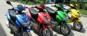
The dashboard of many modern bikes is initially equipped with this useful “informant”. However, in the vast expanses of our Motherland, there are still a huge number of Soviet and Russian-made motorcycles in use (for example, “Ural”, “IZH”, “Voskhod”) that are not equipped with tachometers. By the way, many models of the legendary Harley Davidson and Triumph also do not have standard engine speed indicators. A tachometer for a motorcycle that was not installed during construction can be purchased and installed yourself.
Tachometer selection
Tachometers are used primarily in cars. They are installed to control engine operation.
In order for the determination of engine operation to be as accurate as possible, it is necessary to take care of how to choose the right tachometer.
Many experienced motorcyclists who have extensive experience in tuning motorcycles suggest using domestic tachometers. This is due to the fact that they cause virtually no difficulties during installation. In addition, an important factor in favor of choosing a domestic tachometer is cost. It is very low and acceptable.
Many motorcyclists believe that it is best to choose an imported tachometer. It is believed to have more accurate readings. In addition, it is perfect for imported motorcycles.
Models, manufacturers and prices
The range of tachometers intended for installation on motorcycles, mopeds and scooters is very diverse both in price, design, execution (with an arrow or digital display), and in the number of manufacturers producing products for this purpose.
A universal electronic tachometer (from Chinese or “Kkmoon”) with LED backlight in a stainless steel case (Ø=56 mm, case height – 60 mm) costs only 540÷650 rubles.
For the same 500÷700 rubles you can purchase products with a digital indication of the number of revolutions per minute from Ironwalls or FCD.
Owners of expensive and prestigious brands of motorcycles (however, those not equipped with a standard tachometer) can purchase and install products from the world-famous and well-established Baron, Koso, J&P Cycles or Sunpro. However, the cost of these products will already range from 3,000 to 12,000 rubles.
Ignition system for gasoline engines
Control of engine ignition processes can be organized by several methods:
- Distributor with one ignition coil;
- Distributorless with a dual (triple, quadruple depending on the number of cylinders divided by 2) ignition coil;
- Individual (for each spark plug).
In all cases, the coil receives a powerful pulse with an amplitude of 12V from a breaker (for cars before the 90s), a transistor switch, or directly from the engine control unit. It is from this point that the signal to the tachometer should be taken.
Connection diagram for tachometer to motorcycle
The diagram for connecting a tachometer to a motorcycle is not fundamentally different from its installation on a VAZ-2106 car. The input of the device is connected to the output of the primary winding of the coil, after which the positive and negative wires are connected to the battery. Installing the toggle switch on the positive line will significantly save battery power when the motorcycle is idle.
A two-cylinder unit with single-channel ignition must be equipped with a rectifier. The battery that powers the tachometer is connected to its output. When the TX-193 is directly connected to the generator, the device will fail in the shortest possible time.
In the case of dual-channel ignition, to transmit pulses from both cylinders it is necessary to create an identical tachometer input line. After drilling an additional hole in the bottom, connect the wire to the device terminal.
Three-cylinder motorcycles are usually equipped with three-channel ignition systems. In this case, the connection to the tachometer is made from any two coils. In the same way, pulses are supplied in multi-cylinder equipment, but here it is more advisable to use models designed for this type of engine.
Connecting a tachometer to a single-cylinder unit is a little more complicated. Here it is necessary to adjust the resistor R7, which is responsible for the sensitivity of the measuring device. If necessary (lack of power), you should double the power of capacitor C5, and then readjust the resistor.
Technical solution
Before connecting the tachometer, it is necessary to draw up an electrical connection diagram in order to mentally determine the starting and ending switching points and trace the conductor. Any ignition coil has a terminal (terminal) +15 (ignition on), to which battery voltage is supplied when the key is turned to the first (for some cars, second) position. Under no circumstances should you connect the tachometer to this point; the first time you turn it on, it may fail. High-voltage wires also pose a danger, even to humans. The signal input to which the tachometer should be connected must be precisely determined. In older coils it is designated by the letter "K", it is better to find the exact circuit diagram of the car.
The next, more difficult task is the electrical connection of the nodes. As a conductor, you should take a stranded copper wire with a cross-section of at least 2 sq. mm. with polyvinyl chloride insulation.
The connection points of the wire to the ignition coil are cleaned, mechanically twisted, soldered and carefully insulated. Lay the wire along any electrical harnesses, using plastic clamps, towards the engine compartment bulkhead near the dashboard. You can insert the conductor into the passenger compartment next to any electrical wiring harness. To do this, it is easier to use an elastic string. Finally, connect the conductor to the tachometer signal terminal. In some cars that include modifications with or without a tachometer, you can simply change the dashboard, find the stock wire and connect it to the ignition coil.
We recommend reading:
Feasibility of direct flow, installation instructions
Nowadays, it is not at all difficult to acquire a speed meter for further installation on a bike. As a tachometer on the Izh Jupiter 5 and other Izhmoto models, as mentioned above, the speed meter that is equipped with the VAZ 2106 car (simply popularly called the “Zhiguli Six”) can be safely used. This product can fit well into the standard panel of these Russian Soviet motorcycles In this case, connecting the tachometer to the Izh involves cutting its body to half. All connectors that are connected to the light devices (indicators) of the dashboard must be lowered to the lower limit. After installation, the tachometer on the motorcycle must not sit unevenly, resting against wires and other elements standard bike design.
Electrics and electrical equipment of a scooter
Dedicated to all owners of Chinese scooters...
To begin with, I would like to present a wiring diagram for a Chinese scooter.
Since all Chinese scooters are very similar, like Siamese twins, their electrical circuits are practically no different.
The diagram was found on the Internet and is, in my opinion, one of the most successful, since it shows the color of the connecting conductors. This greatly simplifies the diagram and makes it more comfortable to read.
(Click on the image to enlarge. The image will open in a new window).
It is worth noting that in the electrical circuit of a scooter, just like in any electronic circuit, there is a common wire . On a scooter, the common wire is the minus ( - ). In the diagram, the common wire is shown in green . If you look more closely, you will notice that it is connected to all the electrical equipment of the scooter: headlight ( 16 ), turn relay ( 24 ), instrument panel backlight lamp ( 15 ), indicator lamps ( 20 , 36 , 22 , 17 ), tachometer ( 18 ), fuel level sensor ( 14 ), horn ( 31 ), tail light/brake light ( 13 ), start relay ( 10 ) and other devices.
First, let's go over the main elements of the Chinese scooter circuit.
Egnition lock.
Ignition switch ( 12 ) or “Main switch”. The ignition switch is nothing more than a regular multi-position switch. Even though the ignition switch has 3 positions, the electrical circuit uses only 2.
How to install a tachometer on an Izh
Note that the Izh planet tachometer is designed according to a similar scheme of actions.
There is no need to move the control lamps if the latter are replaced with a box with LEDs. You yourself will appreciate the super-bright indicators of the latter above the brightness that the light indicator elements had in the standard form of the iron horse. You can attach the above box (socket) with LEDs to the end of the tidy. And the body of the latter itself is not difficult to create, using, for example, cases from an old audio cassette. Not a bad excursion into the 1990s, isn't it?
The tachometer on the Ural motorcycle can be equipped according to a similar principle, replacing the speedometer or moving the device for measuring revolutions to a separate area at the steering wheel. Connecting tachometers to an Izh motorcycle is carried out independently with the same success and simplicity as the installation of the latter itself. You can make a colored outline around the new location for the design of light bulbs or LEDs. A bright circle, mostly of a light color, is drawn around each light element. After such a simple innovation, your devices (indicators) will look much better.
Installation and connection
Installation of tachometers additionally installed on a motorcycle is quite simple. A bracket attached to the body of the product allows you to easily install the device on one of the bolts securing the steering wheel to the fork.
Installing the products on the steering wheel in the most convenient place for viewing will allow the use of a special fastening coupling for installing additional equipment. It can be easily purchased for 200–300 rubles at any motorcycle accessories store. Some tachometer models have such fastening devices already included in the delivery kit.
Some manufacturers supply a complete set of a wide variety of fasteners and wires for connection along with the measuring device itself.
The connection diagram is quite simple and will not cause difficulties even for bikers who are not very “advanced” in electrical engineering (note: the colors of the wires are indicated for tachometers from Chinese manufacturers):
- We connect one short wire (usually black) to the switched “+” of the ignition switch;
- the second short one (green) – to the motorcycle frame (in a convenient place);
- the third short (black and yellow) - to the low-voltage contact of the coil going to the breaker;
- two long thin wires (black and red) - parallel to the speedometer light bulb.
Important! The tachometer connection wires from American and European manufacturers have different colors. But unlike Chinese suppliers, the kit necessarily includes a diagram for connecting the device.
How to connect a tachometer to an Izh motorcycle?
After securing the tachometers, you can begin connecting their wires to the electrical wiring elements of the bike.
Simply put, our semi-homemade Izh Planet tachometer, or a device that will work on another bike, has only three wires. The mass goes to the frame of the iron horse.
The plus is connected to the ignition switch (to the positive terminal that comes from the battery). The third wire is mounted on a coil. In the case of the tachometer on Izh Jupiter 5 and other two-cylinder Soviet bikes, there is no difference at all which coil to connect to. The easiest way is to separate the wire to connect to both.
Note that the wire going to the coil needs to be equipped with a “d226d” diode. Often a tachometer is installed on a motorcycle by replacing a capacitor of 0.22 μF (microfarad) with a product with a value of 0.47 μF, for example. This innovation allows you to modernize the bike for use on an Izh motorcycle. The connection diagram for the last wire looks like this.
User voting
Which tachometer from Aliexpress would you choose or recommend?
DRAGON GAUGE 636
0.00 % ( 0 )
RYSJM
0.00 % ( 0 )
DRAGON GAUGE 625-7
100.00 % ( 1 )
Cnsport YC101505
0.00 % ( 0 )
CNSPEED YC100163
0.00 % ( 0 )
QTZOFP
0.00 % ( 0 )
KUS KY
0.00 % ( 0 )
Global Professional
0.00 % ( 0 )
RYSJM
0.00 % ( 0 )
Autoleader
0.00 % ( 0 )
ZMFJH CX8001
0.00 % ( 0 )
MotoQueen MQ926
0.00 % ( 0 )
Suzuki CN125
0.00 % ( 0 )
MotoQueen MQ001
0.00 % ( 0 )
MYiAdv
0.00 % ( 0 )
Evomosa
0.00 % ( 0 )
Ignition circuit elements.
One of the most important electrical circuits in a scooter is the ignition circuit. It includes the CDI ignition module ( 1 ), ignition coil ( 2 ), spark plug ( 3 ).
CDI ignition module.
The CDI ignition module ( 1 ) is made in the form of a small box filled with compound. This makes it difficult to disassemble the CDI unit if it malfunctions. Although the modular design of this unit simplifies the process of replacing it.
There are 5 wires connected to the CDI module. The CDI module itself is located in the bottom of the scooter body near the battery compartment and is secured to the frame with a rubber clamp. Access to the CDI block is made difficult by the fact that it is located in the bottom part and is covered with decorative plastic, which has to be completely removed.
Ignition coil.
Ignition coil ( 2 ). The ignition coil itself is located on the right side of the scooter and is mounted on the frame. It is a kind of plastic barrel with two connectors for connection and a high-voltage wire output that goes to the spark plug.
Structurally, the ignition coil is located next to the start relay. To protect against dust, dirt and accidental short circuits, the coil is covered with a rubber cover.
TACHOMETER FROM VAZ 2106
The idea to install a Shahi tachometer appeared a long time ago. I haven’t gotten around to doing this yet. But still, such a moment has come. Joyfully, I put it on motz, but there was a hitch - it showed 2 times lower frequency than it should have.
The tachometer was pulled out of a friend's car, which he gave me for analysis three years ago. I hadn’t worked on motorcycles before, so the tachometer was lying around in the garage. His hands have reached him now. Tachometer TX 193. It has 3 connectors for connection: +12 volts, ground, input from the ignition coil ('M').
Joyfully, I put it on motz, but there was a hitch - it showed 2 times lower frequency than it should have.
I decided to redo it. The essence of the modification is to replace the capacitor, which is in the ammeter circuit.
Let's get down to business.
First you need to disassemble the tachometer. This is not so difficult (as it turned out) - we unscrew three screws from the back. Then, prying up the metal braid that holds the plastic that holds the glass, we remove them (braid with plastic and glass). It is important to do this as carefully as possible so as not to spoil the appearance of the device. So we took it apart. Now the most important thing is to replace the capacitor. Which? This:
Its capacity is 0.22 µF. In order for the tach not to lie, this capacity must be increased by 2 times. There are 2 ways - either look for a 0.44 µF capacitor, but there are none (((But there are 0.47 µF ones), or solder a similar 0.22 µF capacitor to the existing one (as I did). Who chooses which method is a personal matter. For me, the second The method turned out to be simpler due to the fact that I already had a similar 0.22 uF capacitor.Such capacitors can be removed from old mafons, TVs, etc. After resoldering, we perform the above steps in reverse order.
Now about the connection. We connect one wire with +12 V after the ignition switch to the corresponding connector on the tach, with the ground in the same way. And to the 'M' terminal of the vehicle we throw a wire from the ignition coil, current from the contact where the wire from the ignition distributor is plugged. We are enjoying the operation of the converted device.
PS: for more accurate readings, they can be adjusted with a trimmer located on the tachy board. Please do not hit us with cardan shafts for the photos, since these are not photos at all, but a scanned tachometer!
MicroN
opposit.ru