Payment for goods and downloading of the book in electronic form (PDF format) is made on the website.
To do this, you need to find the book you are interested in and click on the “Buy” button. The price of the book is indicated on the button.
For convenience, the price on the website for residents of Russia, Belarus and Kazakhstan is presented in rubles.
For residents of Ukraine in hryvnias, and for all other countries - dollars.
After clicking on the “BUY” button, a payment window will open where you can select a payment system with which you can pay for the selected book using any bank card (Visa, MasterCard, MIR, etc.)
When you click on the “Pay by bank card” button, the Portmone payment system will open, which is the easiest way to make a payment.
In addition, the website offers four payment systems for payment:
- Yandex (payment from any bank cards, Yandex Money account, QIWI Wallet, terminals, etc.);
- Portmone (payment from any bank cards, Portmone account);
- PayPal (payment from any bank cards, PayPal account);
- WebMoney (payment from any bank cards, payment from WebMoney wallets).
Payment via Yandex Cashier
After selecting payment via Yandex, the Yandex Cashier payment system will launch, where you need to select a convenient payment method (bank card, QIWI, Yandex Money account, etc.)
After specifying payment details and confirming payment, payment for the goods will occur.
If you have a bank card in a currency other than the ruble, then the money will be debited from the card at the rate of the Central Bank of Russia at the time of the purchase.
This payment method is optimal for residents of Russia, Kazakhstan and Belarus.
Official website of the Yandex Kassa payment system https://kassa.yandex.ru
Payment via Portmone
After selecting payment through Portmone, the payment system will launch, where you need to select the payment method: bank card or Portmone account.
The price in the Portmone payment system is converted into dollars at the exchange rate of the Central Bank of the country where you are located.
If you have a bank card in a currency other than the dollar, then the money will be debited from the card at the rate of the Central Bank of your country at the time of the purchase.
After specifying payment details and confirming payment, payment for the goods will occur.
Official website of the Portmone payment system https://www.portmone.com
Features of electrical equipment
The wiring to the Delta and all electrical equipment is quite traditional.
It consists of:
- generator with flywheel;
- electric starter (with relay);
- ignition coils;
- electronic voltage relay;
- spark plug;
- battery;
- electronic switch;
- ignition switch;
- turn relay.
This list is quite understandable to most motorists who have experience in servicing domestic equipment. Moreover, the wiring of the Delta moped is traditional - 12-volt, with a minus to ground.
Payment via PayPal
After selecting payment via PayPal, the PayPal payment system will launch, where you need to select the payment method: bank card or PayPal account.
If you already have a PayPal account, then you need to log into it and make a payment.
If you do not have a PayPal account and you want to pay using a bank card via PayPal, you need to click on the “Create an Account” button - shown with an arrow in the picture.
PayPal will then prompt you to select your country and provide your credit card information.
After specifying the information required to make the payment, you must click on the “Pay Now” button.
Official website of the PayPal payment system https://www.paypal.com
Payment via WebMoney
After selecting payment via WebMoney, the payment system will launch, where you need to select the payment method: bank card or WebMoney wallet.
If you already have a WebMoney wallet, then you need to log into it and make a payment.
If you do not have a WebMoney wallet and you want to pay in another way, you need to select any of the methods that WebMoney offers and make the payment
After specifying payment details and confirming payment, payment for the goods will occur.
Official website of the WebMoney payment system https://www.webmoney.ru/
Downloading a book
After successfully completing the payment (by any method) and returning to the KrutilVertel store from the payment system website, you will be taken to the successful payment page:
On this page you need to indicate your e-mail, where access to download the book will be sent.
If you are already registered on our website, then simply follow the link to your personal account.
The book you purchased will be in your personal account, from where you can always download it.
Please note that after making the payment, you need to return back from the payment system website to the KrutilVertel website.
If for some reason you did not return back to the site and closed the payment system tab with a message about the successful completion of the payment, please let us know - we will send you a letter indicating access to download the book.
Chinese mopeds
Single platform models
Today's realities are such that you can no longer see domestic models on public roads.
Times are changing, and the weakened banner of freedom from the hands of the domestic “Carpathians” and “Verkhovyna” was picked up by Chinese mopeds of the following series:
Let us state a fact: products from China have become widespread in the domestic motorcycle market.
- Alpha;
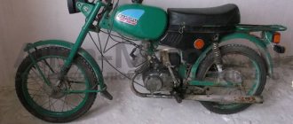
- Delta (DELTA);
- Dino;
- Irbis;
- Viper (VIPER);
- Zip Star;
- Leader;
- Mustang;
- Breeze;
- Dingo;
and other similar models, equipped with everything necessary for travel. These are all Delta “co-platforms” produced by the Chinese manufacturer Chongqing Wonjan motorcycle and the companies that bought a license from it.
For reference: It should be noted that Chinese technology has significantly displaced the products of domestic motorcycle manufacturers on the Russian market. This is noticeable not only in the form of finished products, but also in all kinds of components. For example, the Kovrov Motor Plant abandoned its own production of power units and installed the Lifan engine on its models.
Similarity of design
It is noteworthy that the electrical wiring of the Delta moped is similar to other models, which facilitates maintenance and increases the popularity of the vehicles.
Although seemingly complex at first glance, the electrical connection diagram is quite traditional.
Note! The photo above shows the wiring diagram for a Delta moped that does not have a tachometer on the instrument panel. It is identical for all models of this manufacturer, and differs only in the control of the semi-automatic transmission (Delta Racer model).
The video in this article will provide information regarding maintenance of similar models. For products with an instrument panel containing a tachometer, we publish part of the diagram, which also has differences in the controls. In this case, the wiring for the Delta moped is supplemented with several elements for connection.
The photo shows part of the electrical circuit of the Delta model with a tachometer
Problems when paying with bank cards
Sometimes difficulties may arise when paying with Visa/MasterCard bank cards. The most common of them:
- There is a restriction on the card for paying for online purchases
- A plastic card is not intended for making payments online.
- The plastic card is not activated for making payments online.
- There are not enough funds on the plastic card.
In order to solve these problems, you need to call or write to the technical support of the bank where you are served. Bank specialists will help you resolve them and make payments.
That's basically it. The entire process of paying for a book in PDF format on car repair on our website takes 1-2 minutes.
If you still have any questions, you can ask them using the feedback form, or write us an email at [email protected]
Operating manual for Mokika "Karpaty, Karpaty-2, Luxury, Sport"
CONTENTS: 1. General instructions 2. Safety requirements 4. Technical data 5. Design and adjustment of the main units of the mokika Controls and instruments Engine. Chain drive Front fork Rear suspension Wheels Tires Saddle. Brakes. Rules for operating the mokik Preparing for operation Features of preparing for operation the mokik “Karpaty-2-Lux”. Run-in. Starting the engine Driving Maintenance of the mokika Caring for components and assemblies Cleaning Lubrication Frequency of maintenance of the mokika Rules for storing the mokika Possible malfunctions and their elimination Warranty obligations Coupons for warranty repairs Certificate of acceptance, information about preservation Price. Applications. 1. The procedure for pre-sale preparation of mokiks. Coupon for pre-sale preparation of mokiks. 2. List of enterprises engaged in warranty repair of mokiks.
1. GENERAL INSTRUCTIONS Mokik “Karpaty-2” (Fig. 1), “Karpaty-2-Sport”, “Karpaty-2-Lux” (Fig. 2) is a single-seater transport vehicle designed for business, pleasure and tourist trips around highways and country roads in all climatic zones of the USSR. Mokik "Karpaty-2", "Karpaty-2-Lux" is designed to carry cargo on the trunk up to 15 kg.
Rice. 1. General view of the mokik “Karpaty-2”.
The design feature of the Karpaty-2-Sport motorcycle is a handlebar with a crossbar, like in sports motorcycles, a shortened front wheel guard is raised, and the muffler is upper with a safety screen. For ease of transportation, a handle is installed between the saddle and the rear light. Mokik "Karpaty-2-Lux" is equipped with direction indicators, which increases the convenience and safety of driving a mokik. The operating manual contains the basic information necessary for the proper operation and maintenance of the mokika, compliance with which will ensure the trouble-free operation of your vehicle. Before you start using the mokika, carefully read the “Operating Rules” section of the manual.
Rice. 2. General view of the mokik “Karpaty-2-Sport” “Karpaty-2-Lux”. Due to ongoing work to improve the product, minor changes may be made to the design that are not reflected in this publication.
2. SAFETY REQUIREMENTS Before leaving, check the operation of the clutch and gearbox control mechanisms, brakes, and lighting devices. Switching from 2nd gear to 1st gear at a speed exceeding 12 km/h is prohibited. Do not allow the engine to overheat. Driving a motorcycle with an overheated engine can lead to an accident. Clean the outer surface of the engine in a timely manner. The presence of oil and gasoline on the crankcase can cause the engine to ignite. Do not light matches or smoke when preparing the fuel mixture or refueling the mokik. Do not allow gasoline to leak or evaporate, and do not wash your hands with gasoline.
TECHNICAL DATA
1) Main parameters and dimensions: Mokika base, no more than - 1200 mm Ground clearance at full load and nominal tire pressure, no less than - 100 mm Overall dimensions, no more: length - 1820 mm width - 720 mm height - 1100 mm Weight (dry), no more, mokikov:
“Karpaty-2” — 55 kg “Karpaty-2-Sport” — 55 kg “Karpaty-2-Lux” — 56 kg Maximum load (including the driver), no more than — 980 N (100 kg) Load on the trunk, no more — 147 N (15 kg) Maximum design speed, no more than - 39.9 km/h Braking distance with full load when driving at a speed of 30 km/h and using both brakes, no more than - 7.5 m Control fuel consumption, l/100 km, no more than 2.1 l Note. The control fuel consumption serves to determine the technical condition of the vehicle and is not an operational standard.
2) Engine: Engine type - B501 or B50, gasoline, two-stroke, with counter-flow air cooling. Number of cylinders - 1 Cylinder diameter, mm - 38 Piston stroke, mm - 44 Compression ratio - 7.7-8.5 Cylinder displacement, cm3 - 49.8 Maximum effective power of a run-in engine at a crankshaft speed of 4400-5200 rpm 1, kW (hp) - 1.32 (1.8) Maximum torque of a run-in engine at a crankshaft speed of 3700-4200 min-1, N. m (kgf. m) - 3.03 (0. 31) Engine ignition system - contactless, electronic with a switch-stabilizer unit 3) Power system: Gas tank - stamped, welded Carburetor - K60V Fuel - a mixture of A-76 or A-72 gasoline according to GOST 2084-77 with D8-ASZp-108 oil (M-6Z/10V) in a ratio of 33:1 for a fully run-in engine and 20:1 during the break-in period. It is allowed to use gasoline with an octane rating of up to 86 and special oil AA12TP TU 38.101956-83 in a ratio of 50:1 for a run-in engine and 33:1 during the break-in period. Air cleaner - dry, with a paper filter element EFV-3-1-AU1 TU 112- 013-84 Engine lubrication system - together with fuel Lubricant for gearbox - oil M-8-V GOST 10541–78 - in winter, DV-ASZp-10V (M-63/10V) OST 38.01370-84 - all-season Gas exhaust system — exhaust silencer with partitions for gas throttling and exhaust pipe
4) Power transmission Clutch - multi-plate, operating in oil Gearbox - two-stage Mokika gear shift with B501 engine - foot Gear shift Mokika with B50 engine - manual Gear ratios: - 4.75:1 primary gear - 2.08:1 first transmission - 1.17:1 second gear Overall gear ratio of the starting mechanism - 9.5 Gear ratio from the gearbox to the rear wheel - 2.2 Transmission from the gearbox to the rear wheel - chain, chain PR-12.7-1820-1 GOST 13568-75
5. DEVICE AND ADJUSTMENT OF THE MAIN UNITS OF MOKIKA 5.1. Controls and instruments (Fig. 3).
Rice. 3. Controls and instruments: 1 - rotating gear shift knob (only for Mokika with B50 engine); 2 — light switch with sound signal button; 3 — rear view mirror; 4 — steering wheel; 5 — speedometer; 6 - headlight; 7 — direction indicator switch (only for mokik “Karpaty-2-Lux”); 8 — switch (engine switch); 9 — front wheel brake lever; 10 - rotating carburetor throttle control handle; 11 — cable clamp; 12 — clutch release lever.
The tubular handlebar is attached to the front fork using a cover and bolts. The clutch release lever is designed to disengage and smoothly connect the engine to the power train. The front wheel brake lever is mounted on the body of the carburetor throttle control handle. To brake, press the lever against the steering wheel handle. The rotating carburetor throttle control handle is designed to regulate the amount of combustible mixture entering the engine. When you turn the handle counterclockwise (looking at the end of the handle), the throttle valve opens and the engine speed increases. If the handle is released, it returns to the position corresponding to the idle mode. The rotating gear shift handle of the Mokika with the B50 engine is interlocked with the clutch release lever. You can change gears only when the clutch is disengaged. When the clutch is engaged, the lock in the groove of the lever prevents gear shifting. To disengage the clutch, press the lever to the steering wheel handle. To engage 1st gear, press the clutch release lever to the steering wheel handle, turn the handle clockwise (if you look at the end handle) All the way and smoothly lower the lever. To engage 2nd gear, turn the handle counterclockwise. The neutral position is between first and second gears.
Mokika gear shifting with the B501 engine. To engage 1st gear, press the clutch release lever to the steering wheel handle, press the gear shift lever, which is located on the left side of the engine, all the way down with your foot, then smoothly release the clutch lever. To engage 2nd gear, lift the gear shift lever up, first squeezing the clutch. The headlight switch P25A with a horn button is designed to turn on the low or high beam, rear light and horn. Turn the lever to the right or left to turn on the low or high beam and the rear light. Switch P201 is designed to turn off the engine. To stop the engine, move the lever to the extreme left position. Before starting, make sure the switch lever is in the middle position. The speedometer is used to control the speed of movement and count the distance traveled. The controls include the rear wheel brake pedal, which is mounted on the right side of the mokika frame.
Engine
The Mokika is equipped with a single-cylinder two-stroke engine B50 or B501. The design of the B501 engine is fully consistent with the design of the B50 engine. A distinctive feature of the B501 engine is foot gear shifting.
Rice. 4. Engine (left view): 1 - noise suppression tip; 2 — rubber-metal bushing; 3 - carburetor; 4 — filler plug; 5 — hole for checking the oil level; b — gear shift lever (only for the V501 engine); 7 — drain plug; 8 - seal.
The engine consists of the following main parts: crankcase, cylinder, cylinder head, crank mechanism, clutch, gearbox, starting mechanism, gear shift mechanism (in the B-501 engine), as well as ignition, power supply and exhaust systems. The crankcase is the main power-bearing part of the engine and consists of the left and right halves, tightened with screws. The right cover 4 is attached to the right half of the crankcase with screws (Fig. 5), covering the generator 5, the drive sprocket 8 and, in the B501 engine, the gear shift lever. The gears of the speedometer reducer are mounted in it. The left crankcase cover 24 covering the clutch control mechanism is attached to the left half with screws.
Cylinder head 27 (Fig. 5) and cylinder 26 are cast from aluminum alloy. A spark plug 28 is screwed into the cylinder head. A liner made of special cast iron is pressed into the cylinder. The cylinder to the crankcase, as well as the cylinder head to the cylinder, are secured with four studs and nuts. To seal, a gasket made of special cardboard is installed between the crankcase and the cylinder, and an aluminum gasket is installed between the cylinder head and the cylinder.
Removing and installing the cylinder. Tools: combination wrench, special wrench, open-end wrench 14X24, wrench 8X4.5, screwdriver. To remove the cylinder: - disconnect the exhaust pipe, fuel line, spark plug wire, and also the bolt securing the cylinder head to the frame; - Unscrew the four cylinder mounting nuts and remove the head and gasket; — disconnect the carburetor; — move the piston to bottom dead center (BDC), remove the cylinder and cylinder gasket; — close the hole in the crankcase with a clean rag. Installing the cylinder: - remove the rag from the hole in the crankcase; — install the cylinder gasket and cylinder; — place the gasket, cylinder head and evenly, crosswise, tighten the four fastening nuts in 2-3 steps; — tighten the bolt securing the cylinder head to the frame; - connect the carburetor; — connect the exhaust pipe, fuel line, spark plug wire; — after warming up and completely cooling the engine, tighten the cylinder head nuts.
The crank mechanism consists of a piston 1 (Fig. 5) with two rings 2, a piston pin 3, and a composite crankshaft 6. An arrow is stamped on the spherical surface of the piston, facing the outlet window of the cylinder liner. Pins are pressed into the annular grooves of the piston to fix the position of the piston rings. The piston has two bosses with holes for the piston pin. The annular grooves in the bores of the bosses are designed for retaining rings that hold the piston pin from axial movement. Replacing the piston end: - remove the cylinder head and cylinder; - remove the rings from the piston using three thin steel strips that are placed under the ring (one in the middle, two under the ends of the ring); — insert the removed ring into the upper part of the cylinder to a depth of 10 mm and measure the gap in the lock. If the gap exceeds 0.8 mm, the rings should be replaced. The new ring should have a gap of 0.15-0.30 mm.
Rice. 5. Engine (section): 1 - piston; 2 — piston ring; 3 - finger; 4 — right crankcase cover; 5 - generator; 6 - crankshaft; 7 — speedometer drive; 8 — drive sprocket; 9 - secondary shaft. 10 - 2nd gear gear; 11 — shift clutch; 12 — ratchet clutch; 13 — kickstarter gear; 14 — kick starter spring; 15 — kickstarter shaft; 46 — kickstarter connecting rod; 17 — 1st gear gear; 18 — gear block, 19 — driven drive gear; 20 — spring ring; 21 — shift lever (only for the B501 engine); 22 — clutch release mechanism; 23 — clutch; 24 — left crankcase cover; 25 - crankcase; 26 - cylinder; 27 — cylinder head; 28 - spark plug.
The crankshaft consists of right and left journals and a crank pin and connecting rod pressed into them. The axle cheeks are the counterweights of the crankshaft. The shaft is one-piece. A bushing for piston pin 3 is pressed into the upper head of the connecting rod (Fig. 5). To lubricate the pin, there is a groove in the upper head of the connecting rod. The bearing of the lower head of the connecting rod is a roller, needle K16X22X12. The crankshaft rotates on two ball bearings No. 203. The crank mechanism is lubricated with oil in the fuel mixture.
The clutch operates in an oil bath. To increase the durability of the clutch, follow these rules: — while the engine is running, do not press the clutch release lever for a long time; — when moving away, release the clutch release lever smoothly; — do not drive with the clutch release lever partially pressed.
Clutch adjustment. Tools: special wrench, open-end wrench 14X24, screwdriver. Release locknut 2 (Fig. 7) and, holding adjusting nut 3 with your hand, screw in (unscrew) stop 1, then secure its position with the locknut. When the stop is turned out, the free play of the lever decreases; when screwed in, it increases. If, during adjustment, the length of the threaded part of the stop is insufficient, shorten the free end of the cable. To do this, disconnect the cable from the clutch release mechanism lever, loosen the screw securing the cable holder, move it towards the shell, tighten the screw and install the cable in place. Adjust the free play as indicated above. To check the clutch adjustment, engage 1st gear. When the clutch is disengaged, the wheel should turn freely; when it is engaged, it should not turn.
The transmission of the B501 engine is two-stage. It is controlled by pressing the foot on the gear shift lever 21 (Fig. 5).
Rice. 6. Gear shift mechanism of the B501 engine: 1 - cuff; 2 — shift shaft; 3 — lock washer; 4 — shift drum; 5 — clamp; 6 — shift fork; 7 - leash; 8 - return spring; 9 — pin; 10 — adjusting washer.
The gearbox and gear shift mechanism (Fig. 6) are factory adjusted and do not require additional adjustment during operation.
The transmission of the B50 engine is two-stage. Controlled by rotating gear shift knob 1 (Fig. 3), located on the left side of the steering wheel,
The handle is interlocked with the clutch so that gear shifting can only be done when the clutch is disengaged.
Adjusting the gear shift mechanism and shift gear with the B50 engine. If the gear shift mechanism malfunctions, adjust by increasing or decreasing the free end of the gear shift control cable in the same way as adjusting the free play of the clutch release lever with the same tool (Fig. 7). To do this: – loosen the locknut and place the gear shift knob in the position corresponding to engaging 2nd gear. If 2nd gear does not engage, then the free end of the cable is small. The stop must be screwed into the adjusting nut; — put the handle in the position corresponding to engaging 1st gear. If 1st gear does not engage, it means that the free end of the cable is too large and the stop should be unscrewed. If you cannot adjust the gear shift mechanism, shorten the length of the cable in the same way as when adjusting the clutch. The gear shift lever is accessible after removing the right crankcase cover. If the gearshift mechanism is adjusted correctly, there should be no sound of the clutch rubbing against the gears when the gearshift clutch is in neutral while the engine is running.
Rice. 7. Adjusting the free play of the clutch release lever of a mokika with a B50 engine: 1 - stop; 2 - lock nut; 3—adjusting nut.
Kickstarter (launching mechanism). When starting the engine, the gearshift clutch must be in the neutral position. When you press the kickstarter lever pedal with your foot, rotation is transmitted to shaft 15 (Fig. 5), and ratchet clutch 12 moves to the left, and its end teeth engage with the end teeth of kickstarter gear 13. The starting gear operates through the gearbox and clutch crank mechanism. When the engine starts running, the ratchet clutch disengages from the starting gear. Attention! When starting the B501 engine, the gear shift lever must be in the neutral position.
Removing and installing the kickstarter connecting rod. Tools: combination wrench, hammer and stop. To remove the kickstarter connecting rod 16 (Fig. 5), unscrew and pull out the coupling screw. Using light blows, remove the connecting rod from the splined end of the kickstarter shaft. Installing the kickstarter connecting rod: - remove the rubber plug from the crankcase on the right side of the kickstarter shaft; — place a stop instead to prevent axial movement of the kickstarter shaft when the connecting rod is put on the shaft; — by lightly hitting the end of the connecting rod with a hammer (wooden or with an aluminum mandrel), install the kickstarter connecting rod vertically onto the shaft splines. During impacts on the connecting rod, the kickstarter shaft should not move to avoid deformation and breakage of the kickstarter shaft retaining rings; — tighten the coupling bolt, place the rubber plug on the opposite side of the kickstarter shaft.
Mokika electrical equipment consists of sources and consumers of electrical energy (Fig. 8).
Rice. 8. Schematic diagram of electrical equipment: 1 - generator; 2 — switch-stabilizer block; 3 — rear lamp; 4 — brake light switch; 5 - high-voltage transformer; 6 - candle; 7 — interference suppression tip; 8 — light switch; 9 — sound signal; 10 - headlight; 11 - engine switch.
The source of electricity is an alternating current generator with a nominal voltage of 6 V and a power of 45 W. Electricity consumers: ignition devices, taillight, headlight, sound signal.
The generator serves to power all electricity consumers in Moquique. The main parts of the generator are the stator and the rotor. The rotor is mounted on the tapered end of the right crankshaft journal. Fixed with a key and secured with a bolt. The stator is installed on the engine crankcase. The generator operates in conjunction with a switch-stabilizer unit and a high-voltage transformer mounted on the frame. An electrical impulse comes from the additional winding of the generator to the input of the switch-stabilizer block, and from the output of the block to the high-voltage transformer.
Attention! To avoid failure of the switch-stabilizer unit, it is prohibited to disconnect the pads and check the electrical circuits by shorting to ground (check for a spark) both with the engine running and not running.
The switch-stabilizer unit and the high-voltage transformer do not require maintenance during operation and are not subject to repair.
The A17B spark plug is designed to ignite the working mixture in the engine cylinder. The mixture is ignited by an electrical discharge that occurs on the electrodes of the spark plug at the moment an EMF pulse is generated in the generator sensor. The gap between the electrodes should be 0.5-0.6 mm. If necessary, it can be adjusted by bending the side electrode to the central one. The spark plug is screwed into the cylinder head.
Rice. 9. The procedure for installing the ignition: 1 - stator mounting screw; 2 - stator; 3 — risk on the crankcase; 4 — rotor mounting bolt; 5 - rotor; 6 — right crankcase cover.
Installation and adjustment of the ignition . Tool: screwdriver, combination wrench To obtain the greatest power and efficiency of the engine, it is necessary to ignite the working mixture slightly earlier than the piston approaches top dead center (TDC): the spark discharge on the spark plug electrodes must occur with a certain advance. Optimal ignition timing is 1.2-1.4 mm before TDC,
Early or late ignition leads to loss of power and efficiency, and engine overheating.
Installing the ignition on the engine comes down to installing stator 2 (Fig. 9) relative to rotor 5. Remove the right cover of the crankcase and check that marks 3 on the crankcase coincide with the lower edge of the recess on the stator. If the mark does not coincide with the edge of the recess, install the ignition: loosen the screws securing the generator stator: place the lower edge of the recess on the stator against the mark 3 on the crankcase, then tighten the screws. During operation of the mokika, ignition timing adjustment is not required; periodically check only the tightness of the generator stator screws.
Rice. 10. Headlight adjustment.
Tool: special wrench. The headlight is installed between brackets 13 (Fig. 15) of the front fork and secured with bolts. To properly illuminate the road, the mokika headlight must be adjusted so that the axis of the main beam beam is deflected downwards from the horizontal by 150 mm at a distance of 8 m (Fig. 10).
Engine power system : fuel tank, receiver, air cleaner and K60V carburetor:
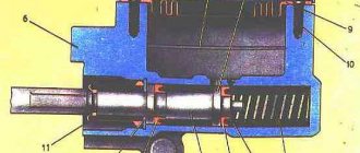
The K60V carburetor (Fig. 11) consists of body 1, throttle 6, carburetor cover 2, float 14 and float chamber 12. The design of the carburetor provides for adjustment of idle speed and mixture quality (operational fuel consumption). Before starting the engine, by rotating screw 7 (Fig. 11), install the throttle so that there is a small gap (2-2.5 mm) between its base and the lower generatrix of the mixing chamber. Screw in adjusting screw 18 completely and then turn it out 0.5-1 turn. Start the engine and warm it up. After the engine warms up, slowly turn out screw 18. The engine speed will first increase and then decrease. The start of the RPM reduction indicates the optimal screw position for a given throttle position. By unscrewing screw 7, again reduce the engine speed and by screwing in screw 18 again find its optimal position. Perform these operations until minimum but quite stable engine speeds are obtained. Check the stability of the idle speed by sharply opening and closing the throttle. If the engine runs stably at low speeds, but stops at the moment of sharp opening of the throttle, enrich the mixture a little by screwing in screw 18. If the engine stops at the moment of sharp closing of the throttle, lean the mixture. In a new engine, friction losses are higher than in a run-in one, and at low speeds rpm it may work unstably. If necessary, set the new engine to a higher idle speed.
Rice. 11. K60V carburetor diagram: 1 - body; 2 - cover; 3 — interconnection lever; 4 — cable guide; b - spring; 6 - throttle; 7—throttle lift screw; 8 — idle hole; 9 — unbalancing channel; 10 — drainage channel; 11 — main system sprayer; 12 — float chamber; 13 — fuel jet; 14 — float; 15 — valve needle; 16 — fuel filter; 17 — fuel supply fitting; 18 — idle speed adjustment screw; 19 — air damper; 20 — air channel; 21 — float sink.
The air purifier (Fig. 12) consists of a paper filter element 4, which is installed on the receiver 1 and secured to it with a pin 2, a stop 7, a washer 5 and a nut 6. The paper filter element is installed in the housing 3.
Fig. 12 installation of the air purifier: 1 – receiver; 2 – hairpin; 3 – body. 4 - filter element; 5 — washer; 6 - nut; 7 - emphasis,
The exhaust system consists of a muffler, which is connected to the engine cylinder using an exhaust pipe. Exhaust gases, passing through the muffler, sharply reduce their speed and cool, and exhaust noise decreases.
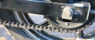
5.3. Chain transmission .
Before installing the chain, remove any dirt from the chain drive sprocket area.
Rice. 13. Determination of chain sag: A - sag 10-25 mm.
Adjust the chain tension so that when pressing with a force of 5-10 kg in the middle between the drive and driven sprockets, the chain sag is at least 10 mm and no more than 25 mm. Do not over-tension the chain as this will overload the bearings. A weakly tensioned chain worsens the operating conditions of the chain drive and leads to rapid wear; during driving, it can jump off the sprocket and damage the engine crankcase.
Adjusting the chain tension (Fig. 14) Tools: open-end wrench 14X24, combination wrench. — Loosen nut 3 of the rear wheel; — loosen locknuts 1 on both sides; — by rotating the adjusting nuts 2, tighten the chain.
Fig. 14. Chain tension adjustment: 1 - lock nut; 2 — adjusting nut; 3 - nut.
After adjusting the chain, the rear wheel should be in the same plane as the front. The distortion is eliminated by uniform rotation of the adjusting nuts on both sides.
5.4. Front fork. The position of the wheel axle in the fork is fixed with bolts 1 (Fig. 15). Disassembling the fork . Tools: special wrench, open-end wrench 14X X24, screwdriver. — Remove the front wheel: — remove bolts 20 securing the steering wheel; — remove the steering wheel together with the cover 19, steering stems 18 and bracket 23; — remove cap 21; — unscrew nut 22; — remove the upper cross-beam 16; — remove holder 17 together with guide 11, springs 9, 10 and rods 6; — pressing on holder 17, knock out pin 15, remove holder 17 and rod 6 with spring 10 and guide 11; — unscrew the upper cone 25; — remove bearing 26; — remove the headlight and signal; — remove frame 12 from the head tube of the frame;
Rice. 15. Front fork: 1 — bolt М8Х1Х25; 2 - nut M8X1: 3 - washer; 4 — front wheel axle; 5 — rod tip; 6 — rod; 7 — spacer sleeve; 8 — nylon bushing; 9 — rebound spring; 10— spring; 11 - guide; 12 - skeleton; 13 — headlight bracket; 14 - reflector; 15 - pin; 16—upper crossbar; 17 - holder; 18— stem; 19 — cover; 20 – bolt M8X1X25; 21 - cap; 22 - nut; 23 — bracket; 24 — front fork rod; 25 — upper cone; 26 — bearing; 27 — frame assembly; 28 - bellows;
— remove the second bearing from the steering column rod. Reassemble the front fork in reverse order. Adjust the steering column bearings in assembled form: remove cap 21, loosen nut 22, and rotate the upper cone 25 until there is no play in the bearings and the front fork turns without jamming.
5.5. Rear suspension. The rear suspension of the mokika consists of a swinging (pendulum) rear fork and two spring shock absorbers. Two bushings 40 are pressed into the holes of pipe 1 (Fig. 16) of the pendulum. A rubber liner 2 is installed in the tip of the rear fork 5, inside of which thrust bushings 37 are installed. Washers 39 are inserted between the end of the pendulum pipe and the tip of the rear fork. The rear fork is connected to the mokika frame using a pin 38, fixed with a nut 3 and a spring washer 4.
Rice. 16. Rear wheel: 1 — pendulum pipe; 2 - liner; 3 — nut M10X1; 4 — spring washer 10L; 5 — rear fork; 6 — tire; 7 - camera; 8 — rim tape; 9 — rim 40EX406; 10 — nipple M3; 11 — knitting needle A-M3; 12 — bushing; 13 — asterisk Z = 33; 14 — adapter; 15 — bolt М8Х1Х22. 16 — spring washer 8L; 17 — nut M8X1; 18 — nut M10X1; 19 - remote bushing; 20 - cover; 21 - buffer; 22 - flange; 23 – washer; 24 — remote bushing; 25 - retaining ring; 26 - brake lever; 27 — cam axis; 28 — nut M8X1; 29 — tension, 30 — wheel axle; 31 — oil seal; 32 — ball bearing No. 201; 33 — brake disc: 34 — rear shock absorber axis; 35 — pad axis: 36 — brake pad; 37 — bushing stop; 38 — hairpin; 39 — washer; 40 - bushing.
The shock absorber (Fig. 17) consists of a body 6, a head with a rod 2 and a spring 3. A rubber buffer 4 is put on the rod, and a nylon bushing 5 is pressed into the body, guiding the movement of the rod. Rubber liners 7 are installed in the holes of the body and head, and metal bushings 1 are installed in the upper liners.
Rice. 17. Rear shock absorber: 1 — bushing; 2 - head with rod; 3 - spring; 4 - buffer; 5 - bushing; 6 — body; 7 - liner.
5.6. Wheels. Removing the rear wheel (Fig. 16). Tools: combination wrench, hammer. — Place the mokik on the stand; — unscrew nut 18 and remove the spring washer; — knock out the rear wheel axle 30 with a light blow; - remove the wheel. Removing the front wheel (Fig. 18). Tools: combination wrench, hammer. — Place the mokik on the stand; — unscrew nut 15 and remove washer 16; — loosen bolts 1 (Fig. 15); — knock out axle 14 of the wheel with light blows (Fig. 18). The wheels are installed in the reverse order. If axial or radial runout of the rim occurs, eliminate it by adjusting the spoke tension. Adjust the spoke tension by turning the spoke nipples using a special wrench included in the tool kit. If it is necessary to replace the bearings in the wheel hub, first press in the bearing on the brake side until it stops. On the other side, insert the spacer sleeve and press in the second bearing.
Rice. 18. Front wheel: 1 - tire; 2 - camera; 3 — rim tape; 4 — rim 40EX-406; 5 — nipple M3: b — spoke A-M3; 7 — bushing; 8 - cover; 9 — washer; 10 — retaining ring; 11 — brake lever; 12 — cam axis; 13 — brake disc; 14 — wheel axle; 15 — nut M10X1; 16 — spring washer 10L; 17 — oil seal; 18 — ball bearing No. 201; 19 — remote bushing; 20 — brake pad; 21 — axis of the pads; 22 — front fork.
5.7. Tires. Mokika tires consist of a tire, tube and rim tape. If the tube is punctured, dismantle the tire and remove the tube. As you step on the tire, press the bead into the recess of the rim. On both sides of the valve, at a distance of approximately 10 cm from each other, insert tire blades and pull the tire bead over the rim bead (Fig. 19). From now on, use one spatula. Then remove the tube from the tire. After inflating the chamber, determine the puncture location by the sound of escaping air. If this fails, immerse the camera in water. Air bubbles will indicate damage. Clean the damaged area and rubber patch with sandpaper and rinse with clean gasoline. When the gasoline has evaporated, glue the patch with rubber cement according to the instructions in the first aid kit. Please remember that this camera repair is temporary. For reliable repair, the damaged area must be vulcanized. Tire installation: - check whether the object that damaged the tube has been removed from the tire; - if the rim tape is removed, put it on the rim, aligning the hole in it with the hole on the rim (the rim tape should completely cover all nipple heads); — with the tire completely removed, place part of the bead in the recess of the rim, use tire shovels to put the entire bead on the rim and slide the tire bead towards the rim bead; — sprinkle the inner surface of the tire with talcum powder, insert the valve into the hole in the rim and insert the slightly inflated inner tube into the tire so that there are no wrinkles; — put on the second bead of the tire on the side opposite the valve, I hold the tire; — tuck the tire bead onto the rim, gradually moving it further and further around the circumference; - having tucked approximately two-thirds of the bead length, step on the tire so that the tucked part of the bead fits into the recess of the rim, and using tire spatulas, tuck the bead to the end; — after mounting the tire on the rim, inflate the inner tube and, tapping along the entire perimeter, check that the tire sits evenly along the entire circumference of the rim; then, to prevent wrinkles from forming in the chamber, completely release the air from it and re-inflate it. Periodically inspect your tires and remove any foreign objects stuck in the tread or sidewall of the tire. Do not allow your mokika to park for long periods of time (more than 30 days) on tires with low pressure. Avoid sudden braking. The 40EX406 wheel rims are equipped with 2.50/85-16″ or 2.75-16″ tires. Tires can be used with a load of up to 100 kg. The guaranteed mileage of tires, subject to operating rules, is 16,000 km, and with the state Quality Mark - 20,000 km.
Rice. 19. Dismantling the tire.
5.8. Saddle . The elongated, removable cushion-type saddle is secured with a lock. To open it, insert the key into the hole in the front of the tool box, which is located under the saddle, and pull the latch. The tool box (Fig. 20) has grooves for fixing the tool.
Brakes.
Shoe brakes are installed on the front and rear wheels of the mokika. The brake pads must be clean, free of dirt and oil, and the brake mechanism must be properly adjusted.
Rice. 20. Tool layout diagram: 1 - special key; 2 - combination key; 3 - screwdriver; 4 — splint blade; 5 — open-end wrench; 6 - key 8X4.5.
The wear of the brake pads should not extend beyond the structural edge of the belt located along the outer contour of the pads. If necessary, to compensate for operational wear of the brake pads, insert washers 8 (included in the kit of spare parts and accessories) between the stop and the end of the brake pad. Adjusting the front brake. Tool: special wrench, open-end wrench 14X24; — Place the mokik on the stand; — by rotating the wheels one by one and simultaneously pressing the brake lever of the front wheel or the brake drive lever of the rear wheel, determine their free play, i.e. the movement before braking begins; the beginning of braking is determined by a sharp slowdown in wheel rotation. If the free play of the front wheel brake lever or the rear wheel drive lever does not fit within the required limits (see the “Technical Data” section), adjust it (Fig. 21, 22), rotate the nut to move the stop in one direction or another and tighten the lock nut. Adjusting the rear wheel brake is shown in Fig. 22.
Rice. 21. Adjusting the front wheel brake: 1 — nut; 2 - emphasis.
Rice. 22. Adjusting the rear wheel brake: 1 - stop; 2 - nut.