Yamaha Cygnus X 125 scooter Yamaha Jog scooters Yamaha Jog RR scooter Yamaha Jog C scooter Yamaha Jog Z scooter Yamaha Super Jog Z scooter Yamaha Jog Z scooter NextZone Yamaha Jog Aprio scooter Yamaha Jog Artistic Spec scooter Yamaha BWs scooter Honda Cub scooters Honda Dio scooters Honda scooter Dio AF 18 Scooter Honda Dio AF 27/28 ZX/ZR Scooter Honda Dio AF 34/35 Scooter Honda Dio AF 34 Cesta Scooter Honda Dio AF 56/57 Scooter Honda Dio AF 62, AF 68 Scooter Honda Dio Z4 AF 63 Scooter Honda Tact AF 24 Honda Tact scooter AF 30/31 Honda Zoomer scooter AF 58 Honda Lead scooter Honda Giorno Crea scooter AF 54 Honda Giorno scooter AF24 Honda Gyro Canopy scooter Huatian Spider 2 scooter Baotian Tanco 50 scooter GX Stinger scooter SYM Jet EuroX scooter LIFAN ZID LF50QT scooter -8A
The files are stored on LetItBit hosting and they can all be downloaded for free. I get income from every download. If you also have a website, you can also start making money with LetItBit.
Keeway
Keeway F-act 125 scooter user manual (Microsoft Word, 508.5 Kb, in Ukrainian)
Keeway F-act 50 scooter user manual (Microsoft Word, 434.5 Kb, in Ukrainian)
Keeway Arn 50 scooter user manual (Microsoft Word, 3.8 Mb, in Ukrainian)
Keeway Hurricane 50 scooter user manual (Microsoft Word, 420.5 Kb, in Ukrainian)
Test drive of the Keeway Speed 150 scooter (PDF, 407 Kb)
Test drive of the Keeway Matrix 50 scooter (PDF, 480 Kb)
MAINTENANCE OF SCOOTERS 50CC, 2-STROKE, WITH CHAIN CVT
MAINTENANCE AND OPERATION OF MOPEDS, SCOOTERS SKYMOTO FOX-50 (QM50QT-3M), FORTUNE-50 (QM50QT-4G), CADET-50 (QM50QT-3E), JUNIOR-50 (QM50QT-B2) 50 CUM, 2-STROKE, WITH CHAIN VARIABLE.
Manufacturer: JINAN QINGQI MOTORCYCLE CO., LTD
SOME RECOMMENDATIONS.
The SKYMOTO FOX-50 (QM50QT-3M), FORTUNE-50 (QM50QT-4G), CADET-50 (QM50QT-3E), JUNIOR-50 (QM50QT-B2) scooters are equipped with a D1E41QMB-2 two-stroke engine with a chain variator. The main features of this engine are to use only good quality mineral or semi-synthetic motor oil for 2-stroke engines!
During the break-in period after major repairs (especially during the first 500 km), it is necessary to add motor oil for a 2-stroke engine to the gas tank in a ratio (1:40).
The oil pump will not work if the rear wheel does not rotate! Do not leave the vehicle idling for a long time with the rear wheel not raised. Place the scooter on the main stand, or turn off the engine, otherwise it may cause engine damage!
To refuel FOX-50, FORTUNE-50, CADET-50, JUNIOR-50 scooters, use 95 octane gasoline with low lead content, this increases the service life of the spark plug, as well as the service life of the engine.
An additional fuel filter for fine fuel purification helps reduce carburetor contamination and reduces the likelihood of water and foreign particles entering the fuel system. Do not store valuable, fragile or heat-sensitive items in the luggage compartment under the seat.
Use SAE 80W-90 API GL5 gear oil.
Cold tire pressure - front tire 1.25 kg/cm2, rear tire 1.75 kg/cm2
It is recommended that the tire be replaced when the tire tread depth is 1.6mm or less.
OPERATION AND MAINTENANCE
The maintenance schedule for SKYMOTO FOX-50, FORTUNE-50, CADET-50, JUNIOR-50 scooters indicates the intervals between periodic maintenance in kilometers and months. If your scooter or scooter is used in difficult conditions, heavy loads and full use of the throttle, or used in dusty areas, some maintenance items should be carried out more often.
ROUTINE MAINTENANCE SCHEDULE
| Interval, km run | 500 | 1000 | 5000 | 10000 | 15000 | 20000 |
| Interval, months | 1 | 2 | 12 | 24 | 36 | 48 |
| * Accumulator battery | I | I | I | I | I | I |
| Nuts in cylinder cover and muffler | I | T | T | T | T | T |
| Cylinder head, cylinder and muffler | I | — | — | C | C | C |
| Carburetor | — | I | I | I | I | I |
| * Air filter | C | ABOUT | ABOUT | ABOUT | ABOUT | ABOUT |
| Spark plug | I | I | R | R | R | R |
| Fuel hoses | I | I | I | R | I | R |
| Motor oil for Happy 50 | R | R | Z | Z | Z | Z |
| Transmission oil | R | R | R | R | R | R |
| Engine oil pump | I | I | I | I | I | I |
| * Brakes | I | I | I | I | I | I |
| Front fork | I | I | I | I | I | I |
| * Steering wheel | I | I | I | I | I | I |
| * Rear shock absorber | I | I | I | I | I | I |
| * Tires | I | I | I | I | I | I |
| Fuel filter | — | R | R | R | R | R |
| Mounting nuts and bolts | T | T | T | T | T | T |
| Cable lubrication | — | — | lubricant | — | lubricant | — |
NOTE:
I = Inspect and adjust, C = Clean, R = Replace, T = Tighten, O = Clean every 500 km, Z = Replace every 3000 km*
* — If the scooter is used in places with high dust levels (on dirt roads), the air filter must be cleaned every 200 km.
ACCUMULATOR BATTERY
The scooter battery, which runs on liquid electrolyte, must be periodically checked and maintained. When checking, the fluid level in the battery should remain in the middle between the upper and lower limits. If the readings are below the minimum level, distilled water must be added to the maximum level.
SPARK PLUG
It is recommended to install an E5RTC spark plug on FOX-50, FORTUNE-50, CADET-50, JUNIOR-50 scooters; replacement with an E7RTC spark plug is possible. To clean the spark plug, use a small wire brush to remove carbon deposits every 3,000 km. Adjust the spark plug gap so that the distance is 0.6~0.8mm. It is recommended to replace the spark plug after every 5,000 km. If the spark plug is very black, you are using a rich mixture or a cold plug. A normal working spark plug should be slightly brown or tan in color. If the color is white or almost shiny, the plug is “hot” and needs to be replaced. Do not pinch the spark plug too hard to avoid damaging the cylinder head.
FUEL HOSE
It is recommended to change the fuel supply hoses every two years.
AIR FILTER
The air filter element on scooters is made of polyurethane foam. If the filter element is clogged with dust, the intake resistance will increase, which will affect power and increase fuel consumption. Check and clean the air filter element according to the following procedure:
1) Remove two screws. 2) Move the two installation clamps. 3) Remove the air filter cover.
4) Remove the filter element.
WASHING THE FILTER ELEMENT OF THE SCOOTER AIR FILTER.
1) Fill the sink tray with a solution of water and washing powder. Immerse the filter element in the solution and wash it.
2) Squeeze out the filter element by squeezing it between the fingers of both hands. Do not twist or twist the filter element - this will cause cracks.
3) Immerse the filter elements in the engine oil solution (B), then squeeze the oil from the filter element to mix some moisture with the oil.
4) Install the cleaned air filter element onto the scooter in reverse order. Make sure the filter element is seated tightly and properly.
During the cleaning operation, carefully inspect the air filter element for any tears in the material. A torn filter element must be replaced with a new one. When using the scooter in dusty conditions, the filter element must be cleaned frequently. Running the engine without a filter element will increase its wear. Always ensure that the filter element is in excellent operating condition. Engine life depends largely on this single component.
CARBURETOR
Smooth functioning of the scooter carburetor is one of the basic requirements that is necessary for your engine. Do not attempt to change its setting. There are two ways to adjust the carburetor that you can carefully use - engine idle speed and choke clearance. Periodically adjust the engine idle speed and choke clearance.
ADJUSTING ENGINE IDLE SPEED
1) Start the engine and let it warm up.
2) After the engine has warmed up, turn the throttle lock bolt so that the engine can reach 1700-1900 rpm . The engine idle speed should be adjusted after the engine has warmed up.
ADJUSTING THE THROUGH CABLE
1) Loosen the locknut.
2) Adjust the cable tension by rotating the adjuster to obtain a deflection of 0.5-1.0 mm .
3) After adjusting the slack, tighten the locknut.
CHECKING AND ADJUSTING THE BRAKES
ADJUSTING THE FRONT DRUM BRAKE
The scooters have a front drum brake. The gap between the front brake handle and the steering wheel handle should be 10-20mm. Turn the front brake adjusting nut clockwise or counterclockwise until you reach the recommended clearance.
ADJUSTING THE REAR BRAKE
on a scooter, the gap between the rear brake handle and the handlebar should be 10-20mm .
Checking the gap and adjusting:
1) Turn the rear brake adjusting nut clockwise or counterclockwise until you obtain the recommended clearance. Turning the adjusting nut clockwise will decrease the clearance.
2) After adjusting the clearance, check whether there is any friction when the wheel rotates. Check, when the lever is firmly compressed, that there is sufficient clearance between the brake lever grip.
ADJUSTING THE SCOOTER KICK STARTER CLUTCH CONTROL BAR.
If you cannot start the engine with a foot starter (the foot starter lever moves freely) when the rear brake handle is depressed, it means that the starting mechanism in the gearbox is not engaged. Turn the clutch linkage adjusting nut slightly clockwise. Turn the nut until you are able to start the engine using the foot starter with the rear brake lever depressed. When the rear brake handle is released, the kick starter lever should move freely.
If you are able to kick start the engine with the rear brake lever released, turn the clutch linkage adjusting nut slightly counterclockwise. Turn the nut until you can no longer kick start the engine with the rear brake handle released. After adjustment, firmly tighten the two clutch linkage adjusting nuts.
PROCEDURE FOR CHANGING TRANSMISSION OIL ON A SCOOTER
To check the transmission oil level, you need to unscrew
oil level control screw, at this time the scooter should stand on a flat surface on the center stand. The oil level should be level with the hole in the oil level screw. The oil change must be carried out with the warm engine not running. Remove the oil filler plug. Place a container for used oil under the drain hole and unscrew the oil drain plug. Wait until all the oil flows out of the drain hole. To drain the oil completely, tilt the scooter slightly. Screw and clamp the drain plug, being careful not to damage the sealing washer. Unscrew the oil level control screw and pour oil into the oil filler hole, excess oil will flow out through the oil level control screw hole. Tighten and tighten the oil level screw and the filler cap.
FUSE
The fuse on the scooter is located near the battery. If there is any problem in the electrical system, check the fuse first. If the fuse has melted, replace it with a new 10A fuse.
PREPARATION OF SCOOTERS, MOTOR SCOOTERS, MOPEDS FOR STORAGE
If the scooter is not going to be used for an extended period of time (winter storage or any other reason), the engine requires special maintenance.
1. Place the scooter on its main support.
2. Unscrew the spark plug, then remove the air filter from the carburetor, turn the throttle until it stops, then you need to simultaneously inject a preservative (for example, WD 40) into the carburetor ( WHERE IS THE AIR SUPPLY ) and turn
engine until the first appearance of steam from the spark plug hole. Screw the spark plug into the cylinder, secure the air filter to the carburetor.
3. Fill the fuel tank to the top with fuel mixed with a fuel stabilizer. Drain the carburetor or run the engine for a few minutes until stabilized fuel enters the carburetor.
4. Remove the battery from the scooter or scooter. Clean the outside of the battery with a mild detergent and remove any corrosion from cable connections, wires and clamps. Store the battery in a room with a temperature above zero degrees. During storage, you need to charge the battery periodically (once a month).
5. Lower the tires to normal pressure.
6. We recommend coating all plastic and rubber parts with a preservative. Coat unpainted surfaces with a rust preventive liquid. Cover painted surfaces with car wax.
PROCEDURE FOR PREPARING SCOOTERS AND MOTOR SCOOTERS FOR OPERATION
— Wipe or wash the scooter.
— Unscrew the spark plug, crank the engine several times while pressing the foot starter lever, and screw the spark plug back in.
— Install the battery.
— Pump up the tire pressure.
— Check the scooter or scooter before the trip.
When repairing scooters SKYMOTO FOX-50 (QM50QT-3M), FORTUNE-50 (QM50QT-4G), CADET-50 (QM50QT-3E), JUNIOR-50 (QM50QT-B2), we recommend using only original spare parts from JINAN QINGQI MOTORCYCLE CO .,LTD. This will help extend the life of your scooter.
Tornado scooter repair manual
Your Atlant moped is a product manufactured using professional equipment from high-quality components. It is equipped with an electronic ignition system, an electric starter, and its consumer properties are at the level of the world's leading manufacturers - economical engine, low noise level, good acceleration dynamics and excellent handling. All these qualities are combined so that your Atlant 50 scooter becomes a high-tech and comfortable conqueror of city roads, but still requires servicing.
This book is not a scooter repair manual. This instruction manual for Atlant 50cc provides detailed information about your 4-stroke 50cc moped - how to ride and maintain it correctly. The manufacturer hopes for your understanding regarding the possible discrepancy between the illustrations in this manual and the real moped; this is due to the constant modernization of production and differences in the configuration of the models.
Please read this instruction manual carefully and follow the recommendations to make your experience with your moped enjoyable and mutually beneficial. We wish you good luck on the roads and enjoy using our products.
Ignition circuit elements.
One of the most important electrical circuits in a scooter is the ignition circuit. It includes the CDI ignition module ( 1 ), ignition coil ( 2 ), spark plug ( 3 ).
CDI ignition module.
The CDI ignition module ( 1 ) is made in the form of a small box filled with compound. This makes it difficult to disassemble the CDI unit if it malfunctions. Although the modular design of this unit simplifies the process of replacing it.
There are 5 wires connected to the CDI module. The CDI module itself is located in the bottom of the scooter body near the battery compartment and is secured to the frame with a rubber clamp. Access to the CDI block is made difficult by the fact that it is located in the bottom part and is covered with decorative plastic, which has to be completely removed.
Ignition coil.
Ignition coil ( 2 ). The ignition coil itself is located on the right side of the scooter and is mounted on the frame. It is a kind of plastic barrel with two connectors for connection and a high-voltage wire output that goes to the spark plug.
Structurally, the ignition coil is located next to the start relay. To protect against dust, dirt and accidental short circuits, the coil is covered with a rubber cover.
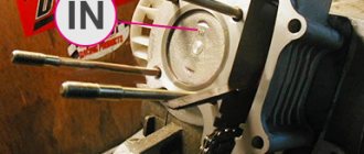
Spark plug.
A7TC spark plug ( 3 ).
The spark plug turned out to be cleverly hidden on the scooter, and it can take quite a long time to find it the first time. But if we “walk” along the high-voltage wire from the ignition coil, the wire will lead us straight to the spark plug cap.
The cap is removed from the candle with a little effort. It is fixed to the spark plug contact with an elastic metal latch.
It is worth noting that the high-voltage wire is connected to the cap without soldering. The insulated stranded wire is simply screwed onto the screw contact built into the cap. Therefore, you should not pull the wire too hard, otherwise you can pull the wire out of the cap. This can be easily fixed, but the wire will have to be shortened by 0.5 - 1 cm.
It's not so easy to get to the spark plug itself. To dismantle it, a socket wrench is required. With its help, the candle is simply unscrewed from its seat.
Starter.
Starter ( 8 ). The starter is used to start the engine. It is located in the middle part of the scooter next to the engine. It's not easy to get to.
The starting of the starter is controlled by the starting relay (10).
The start relay is located on the right side of the scooter frame. The starting relay receives a thick red wire from the positive terminal of the battery. This is how the start relay is energized.
Fuel gauge and indicator.
The fuel level sensor ( 14 ) is built into the fuel tank.
There are three wires coming from the sensor. Green is common (minus power), and the other two sensors are connected to the fuel level indicator ( 11 ), which is installed on the dashboard of the scooter.
The fuel sensor ( 14 ) and indicator ( 11 ) are one device and are powered by a constant stabilized voltage. Since these two devices are spaced apart, they are connected by a three-pin connector. The positive supply voltage is supplied to the fuel indicator and sensor via the black wire from the ignition switch.
If you open the three-pin connector coming from the fuel sensor, the fuel indicator will no longer show the fuel level in the tank. Therefore, if your fuel indicator does not work, then check the connecting connector between the sensor and the fuel indicator, and also make sure that they are receiving power.
It is also worth remembering that the supply voltage is supplied to the sensor and indicator when the ignition switch is in the closed position ( 12 ). According to the diagram, this is the right position.
Turns relay.
Turn relay or breaker relay ( 24 ). Serves to control the front and rear turn signal lamps.
As a rule, the turn relay is installed next to the instruments (speedometer, tachometer, fuel level indicator) on the dashboard. In order to see it you need to remove the decorative plastic. It looks like a small plastic barrel with three terminals. When the turn signals are on, it makes characteristic clicks with a frequency of about 1 Hz.
After the turn relay, a turn signal switch ( 23 ) is installed. This is an ordinary key switch that switches the positive voltage from the turn relays (gray wire) to the lamps. If you look at the diagram, when the switch is in the right position ( 23 ), we supply voltage through the blue wire to the right front ( 21 ) and right rear ( 32 ) indicator lamp. If the switch is in the left position, then the gray wire is shorted to the orange one, and we supply power to the left front ( 19 ) and left rear ( 33 ) indicator lamp. In addition, in parallel with the corresponding indicator lamps ( 19 , 20 , 32 , 33 ), signal lamps ( 20 and 22 ) are connected, which are located on the dashboard of the scooter and serve as a purely informational signal for the scooter driver.
Sound signal.
The sound signal ( 31 ) of the scooter is located under the plastic fairing of the scooter next to the relay regulator.
The audio signal supply voltage is constant. It comes from a relay regulator or battery (if the engine is turned off) through the ignition switch and the horn button ( 25).